Tower Mounted Amplifiers, Diagnostics and Isolation ... - Opticus
Tower Mounted Amplifiers, Diagnostics and Isolation ... - Opticus
Tower Mounted Amplifiers, Diagnostics and Isolation ... - Opticus

Create successful ePaper yourself
Turn your PDF publications into a flip-book with our unique Google optimized e-Paper software.
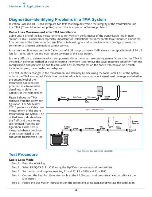
MODE FREQ/DIST AMPLITUDE SWEEP1START AUTOCALSCALE3 4SAVESETUPLIMIT7SAVEDISPLAY9ONOFF2RECALLSETUP5 6ESCAPECLEARMARKERENTER8RECALL RUNDISPLAY HOLD0 +/-PRINT.SYSSiteMasterApplication Note<strong>Diagnostics</strong>–Identifying Problems in a TMA SystemInsertion Loss <strong>and</strong> DTF-Load sweep are two tests that help determine the integrity of the transmission linein a TMA (<strong>Tower</strong> <strong>Mounted</strong> Amplifier) system that is suspected of having problems.Cable Loss Measurement after TMA InstallationCable Loss is one of the key measurements to verify system performance of the transmission line in BaseStations. Cable Loss becomes especially important for installations that incorporate tower mounted amplifiers.The purpose of the tower mounted amplifier is to boost signal <strong>and</strong> to provide better coverage to areas thatconventional antenna orientations cannot service.A transmission line measured with Cable Loss of 6 dB is approximately 2 dB above an acceptable level of 3-4 dBloss for 150 ft. cable run <strong>and</strong> may reduce coverage of the Base Station.It is very difficult to determine which components within the system are causing system failure after the TMA isinstalled. A common method of troubleshooting the system is to remove the tower mounted amplifier from theconfiguration <strong>and</strong> perform an end-to-end Cable Loss measurement on the entire transmission line whichincludes jumpers, main feeder, <strong>and</strong> adapters.This test identifies changes in the transmission line assembly by measuring the total Cable Loss of the systemwithout the TMA connected. Cable Loss provides valuable information about signal level coverage <strong>and</strong> whetherthe output level of thetransmitter has been compromiseddue to excessivesignal loss in either theTMAAntennajumpers or the main feeder.Figure 8 shows the TMAremoved from the system configuration.The Site MasterS251C performs a Cable Lossmeasurement of the entiretransmission line system. Thedotted lines indicate wherethe TMA <strong>and</strong> the antennaare removed from the configuration.Cable Loss ismeasured when a precisionshort is connected to theend of the transmission line.Site Master S251CJumper Main Feeder TMA JumperTx/RxTest PortCable Jumper Main FeederFigure 7. TMA InstallationTx/RxTMAJumperAntennaJumperTMARemovedAntennaJumperAntennaRemovedCalibratedShortTest Procedure8Figure 8. Insertion Loss Measurement without TMACable Loss ModeStep 1. Press the MODE key.Step 2. Select FREQ-CABLE LOSS using the Up/Down arrow key <strong>and</strong> press ENTER.Step 3. Set the start <strong>and</strong> stop frequencies, F1 <strong>and</strong> F2, F1 = 1850 <strong>and</strong> F2 = 1990.Step 4. Connect the Test Port Extension cable to the RF Out port <strong>and</strong> press START CAL to calibrate theSite Master.Step 5. Follow the Site Master instructions on the screen <strong>and</strong> press SAVE SETUP to save the calibration.