MC7205 MC7205 THX® Five Channel Power Amplifier
MC7205 MC7205 THX® Five Channel Power Amplifier
MC7205 MC7205 THX® Five Channel Power Amplifier

Create successful ePaper yourself
Turn your PDF publications into a flip-book with our unique Google optimized e-Paper software.
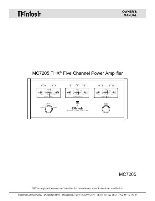
OWNER’SMANUAL<strong>MC7205</strong> THX ® <strong>Five</strong> <strong>Channel</strong> <strong>Power</strong> <strong>Amplifier</strong><strong>MC7205</strong>THX is a registered trademarks of Lucasfilm, Ltd. Manufactured under license from Lucasfilm Ltd.McIntosh Laboratory, Inc. 2 Chambers Street Binghamton, New York 13903-2699 Phone: 607-723-3512 FAX: 607-724-0549
Safety InstructionsIMPORTANT SAFETYINSTRUCTIONS!PLEASE READ THEM BEFOREOPERATING THIS EQUIPMENT.WARNING SHOCK HAZARD -DO NOT OPEN.The lightning flash with arrowhead, within an equilateraltriangle, is intended to alert the user to the presence ofuninsulated “dangerous voltage” within the product’senclosure that may be of sufficient magnitude to constitutea risk of electric shock to persons.AVIS RISQUE DE CHOC -NE PAS OUVRIR.The exclamation point within an equilateral triangle isintended to alert the user to the presence of importantoperating and maintenance (servicing) instructions inthe literature accompanying the appliance.NO USER-SERVICEABLEPARTS INSIDE. REFERSERVICING TOQUALIFIED PERSONNELTo prevent the risk of electric shock, do not removecover (or back). No user serviceable parts inside. Referservicing to qualified personnel.General:1. Read all the safety and operating instructions, containedin this owner’s manual, before operating thisequipment.2. Retain this owner’s manual for future reference aboutsafety and operating instructions.3. Adhere to all warnings and operating instructions.4. Follow all operating and use instructions.5. Warning: To reduce risk of fire or electrical shock,do not expose this equipment to rain or moisture.This unit is capable of producing high sound pressurelevels. Continued exposure to high sound pressurelevels can cause permanent hearing impairmentor loss. User caution is advised and ear protectionis recommended when playing at high volumes.6. Caution: to prevent electrical shock do not use this(polarized) plug with an extension cord, receptacleor other outlet unless the blades can be fully insertedto prevent blade exposure.Attention: pour pevenir les chocs elecriques pasutiliser cette fiche polarisee avec un prolongateur,une prise de courant ou un autre sortie de courant,sauf si les lames peuvent etre inserees afond ans enlaisser aucune partie a decouvert.7. For added protection for this product during a lightningstorm, or when it is left unattended and unused for longperiods of time, unplug it from the wall outlet. Thiswill prevent damage to the product due to lightning orpower line surges.8. Do not use attachments not recommended in thisowner’s manual as they may cause hazards.Installation:9. Locate the equipment for proper ventilation. For example,the equipment should not be placed on a bed,sofa, rug, or similar surface that may block ventilationopenings; or, placed in a built-in installation, such as abookcase or cabinet, that may impede the flow of airthrough the ventilation openings.10. Locate the equipment away from heat sources such asradiators, heat registers, stoves, or other appliance (includingamplifiers) that produce heat.11. Mount the equipment in a wall or cabinet only as describedin this owner’s manual.12. Do not use this equipment near water; for example,near a bathtub, washbowl, kitchen sink, laundry tub, ina wet basement or near a swimming pool, etc.13. Do not place this product on an unstable cart, stand,tripod, bracket, or table. The equipment may fall, causingserious injury to a person, and serious damage tothe product.Connection:14. Connect this equipment only to the type of AC powersource as marked on the unit.15. Route AC power cords so that they are not likely to bewalked on or pinched by items placed upon or againstthem, paying particular attention to cords at plugs, conveniencereceptacles, and the point where they exitfrom the instrument.16. Do not defeat the inherent design features of the polarizedplug. Non-polarized line cord adapters will defeatthe safety provided by the polarized AC plug. If theplug should fail to fit, contact your electrician to replaceyour obsolete outlet. Do not defeat the safetypurpose of the grounding-type plug.3
Safety Instructions con’t,Introduction and Performance Features17. Do not overload wall outlets, extension cords or integralconvenience receptacles as this can result in a riskof fire or electric shock.Care of Equipment:18. Clean the instrument by dusting with a dry cloth. Unplugthis equipment from the wall outlet and clean thepanel with a cloth moistened with a window cleaner.Do not use liquid cleaners or aerosol cleaners.19. Do not permit objects of any kind to be pushed and/orfall into the equipment through enclosure openings.Never spill liquids into the equipment through enclosureopenings.20. Unplug the power cord from the AC power outletwhen left unused for a long period of time.Repair of Equipment:21. Unplug this equipment from the wall outlet and referservicing to a qualified service personnel under the followingconditions:A. The AC power cord or the plug has been damaged.B. Objects have fallen, or liquid has been spilled intothe equipment.C. The equipment has been exposed to rain or water.D. The equipment does not operate normally by followingthe operating instructions contained withinthis owner’s manual. Adjust only those controlsthat are covered by the operating instructions, as animproper adjustment of other controls may resultin damage and will often require extensive work bya qualified technician to restore the product to itsnormal operation.E. The equipment has been dropped or damaged in anyway.F. The equipment exhibits a distinct change in performance- this indicates a need for service.22. Do not attempt to service beyond that described in theoperating instructions. All other service should be referredto qualified service personnel.23. When replacement parts are required, be sure the servicetechnician has used replacement parts specified byMcIntosh or have the same characteristics as the originalpart. Unauthorized substitutions may result in fire,electric shock, or other hazards.24. Upon completion of any service or repairs to this product,ask the service technician to perform safety checksto determine that the product is in proper operatingcondition.IntroductionNow you can take advantage of traditional McIntosh standardsof excellence in the <strong>MC7205</strong>, power amplifier. <strong>Five</strong>200 watt, high current output channels will deliver outstandingaudio performance for your McIntosh Home TheaterSystem. The <strong>MC7205</strong> is THX certified and easilymeets the demanding Lucasfilm, Ltd., standards for accuracyin home theater electronics.Performance Features· <strong>Power</strong> OutputThe <strong>MC7205</strong> consists of five separate power amplifierchannels with less than 0.005% distortion at rated poweroutput. This is over 600 watts of McIntosh power in asingle package.· <strong>Power</strong> GuardAll five channels include the patented McIntosh <strong>Power</strong>Guard circuit that prevents the amplifier from beingoverdriven into clipping with its harsh distorted sound thatcan also damage your valuable loudspeakers.· Sentry Monitor and Thermal ProtectionMcIntosh Sentry Monitor power output stage protectioncircuits are present on all five channels to ensure the<strong>MC7205</strong> will have a long and trouble free operating life.Built-in thermal protection circuits guard against overheatingwhich could shorten the normal long life expectancy ofyour McIntosh power amplifier.· Direct Current ProtectionDirect Current sensing circuits on each channel provideextra protection for your valuable loudspeakers.· Illuminated <strong>Power</strong> MetersThree front panel, illuminated output wattmeters can beselected to precisely indicate the power output of each ofthe five channels as well as the relative power output producedby a THX certified powered subwoofer amplifier.· Convenient Single Cable HookupA rear panel connector provides for the convenience of usinga single cable, (DB25 computer style) to receive all audioand power control signals from a McIntosh THX ControlCenter.4
InstallationInstallationThe <strong>MC7205</strong> can be placed upright on a table or shelf,standing on its four feet. It also can be custom installed in apiece of furniture or cabinet of your choice. The requiredpanel cutout, ventilation cutout and unit dimensions areshown.Always provide adequate ventilation for your <strong>MC7205</strong>.Cool operation ensures the longest possible operating lifefor any electronic instrument. Do not install the <strong>MC7205</strong>directly above a heat generating component such as a highpowered amplifier. If all the components are installed in asingle cabinet, a quiet running ventilation fan can be a definiteasset in maintaining all the system components at thecoolest possible operating temperature.A custom cabinet installation should provide the followingminimum spacing dimensions for cool operation. Allowa ventilation opening of 6 inches (15.24 cm) in height, runningthe full width of the front panel, directly above thefront top of the <strong>MC7205</strong>. Provide additional ventilation of2 inches (3.81cm) below the bottom and 1 inch (2.54 cm)on each side of the amplifier, so that airflow is not obstructed.Allow 21 inches (53.3 cm) depth behind themounting panel, which includes clearance for connectors.Allow 1-1/8 inches (2.9 cm) in front of the mounting panelfor knob clearance. Be sure to cut out a ventilation hole inthe mounting shelf according to the dimensions in thedrawing.ÅPPÅPPÅPP2XWOLQHÃRIÃ)URQWÃ3DQHO(GJHÃRIÃ&XWRXWFront View of a <strong>MC7205</strong>custom installed(QGÃ&DSVÅPPÃÃÃÅÃÃÃÃPP3DQHOÃ+HLJKWÃÃÅÃÃÃPP)URQWÃ9LHZÅP PÅP P6XSSRUWÃ6KHOI%RWWRPÃRIÃ&XWRXWÃDQGÃ7RSRIÃ6XSSRUWÃ6KHOIÃ0XVW&RLQFLGH0RXQWLQJÃ6XUIDFHSide View of a <strong>MC7205</strong>custom installedÅÃ+LJKÃ9HQWLODWLRQÃ2SHQLQJ2XWOLQHÃRIÃ8QLW0RXQWLQJÃ%UDFNHWÃDWÃ%RWKÃ6LGHVÃRIÃWKHÃ5HDUÃ3DQHO)DVWHQÃZLWKÃÃ[ÃÃ0DFKLQHÃ6FUHZÃDQGÃ:DVKHUÃWRÃ&KDVVLV)DVWHQÃZLWKÃÃ[ÃÃ:RRGÃ6FUHZÃDQGÃ:DVKHUÃWRÃ6XSSRUWÃ6KHOI6LGHÃ9LHZ6XSSRUWÃ6KHOI&XWÃ2XWÃ&HQWHUIRUÃ9HQWLODWLRQBottom View of a <strong>MC7205</strong>custom installedÅÅ&XWÃ2XWÃ&HQWHUIRUÃ9HQWLODWLRQ%RWWRPÃ9LHZÅ0RXQWLQJ6XUIDFH5
<strong>MC7205</strong> Rear Panel Controls andConnections<strong>MC7205</strong> Rear Panel Controls andConnectionsINPUTS for discrete audio cablesfrom a preamplifier or controlcenter audio outputsINPUT for discrete audio cablefrom a preamplifier or controlcenter audio outputINPUTS for discrete audio cablesfrom a preamplifier or controlcenter audio outputsConnect the <strong>MC7205</strong>power cord to a liveAC outlet. Refer to informationon the backpanel to determine thecorrect voltageSUB IN/OUT accepts asubwoofer input signal toactivate the subwooferpower meter circuit. If a 25conductor cable is beingused with a McIntosh ControlCenter this jack willprovide a signal out to asubwoofer amplifierTHX INPUT Connectoraccepts a 25 conductorcable that connects allaudio and power controlsignals from a McIntoshControl CenterIndividual InputLEVEL controlsfor the Left channelsIndividual InputLEVEL controls forRight channels andCenter channelSUB METER CALcontrol for metercalibration of theSubwoofer <strong>Channel</strong>Main Fuse holder,refer to infromationon the back panelof your <strong>MC7205</strong> todetermine the correctfuse size andratingOUPUT Connectionsfor loudspeakersOUPUT Connectionsfor loudspeakersOUPUT Connectionsfor loudspeakersPOWER CONTROL In receivesturn on/off signals from a McIntoshcomponent and the POWER CON-TROL Out sends that turn on/offsignal to the next McIntosh component6
123456789123456789123456789123456789123456789123456789123456789123456789123456789123456789123456789123456789123456789123456789123456789123456789123456789123456789123456789123456789123456789123456789123456789123456789123456789123456789123456789123456789123456789123456789123456789123456789123456789123456789123456789123456789123456789123456789123456789123456789123456789123456789123456789123456789123456789123456789123456789123456789123456789123456789123456789123456789123456789123456789123456789123456789123456789123456789123456789123456789How to Connect the <strong>MC7205</strong>How to Connect the <strong>MC7205</strong>1. Connect the <strong>MC7205</strong> power cord to a live AC outlet.2. Prepare the loudspeaker hookup cables as follows:A. Carefully remove sufficient insulation from theloudspeaker cable ends to just fit within the bindingpost with no exposed wire accessible. Refer tofigure 1.B. If the cable is stranded, carefully twist the strandstogether as tightly as possible. Refer to figures 2 &3.Note: If desired, the twistedcable section can betinned with a solder ironto keep the strandstogether and/or attachappropriate connectorends.C. Insert the bare section of thecable end or connector intothe access hole, and tightenthe terminal nut clockwiseuntil the cable is firmlyclamped into the terminal sothe wires cannot slip out. Refer to figure 4.McIntosh MX132 A/V Control CenterMcIntosh SL-1 <strong>Power</strong> Sub-WooferD. Insert the bare section of the cable end or connectorinto the access hole, and tighten the terminal nutclockwise until the cable is firmly clamped into theterminal. Refer to figures 5 & 6.Note: The bare sections of the cable ends or the noninsulated part of the connectors must not be exposed oneither side of the terminal access hole.E. Repeats Steps A through D for each speaker cableused with the amplifier.3. Connect the loudspeaker cables to theappropriate output connectors, beingcareful to observe the correct polaritiesand install the protective coversthat were supplied. Refer to figure 7.4. Connect a single DB25 computer typecable from the multi-channel outputof a control center to the THX Inputconnector for all six audio channelsand power control.Figure 75. Connect the <strong>MC7205</strong> Sub In/Out to the McIntosh SL-1Subwoofer THX input and a power control cable fromthe <strong>MC7205</strong> <strong>Power</strong> Control Out to the SL-1 <strong>Power</strong>Control In.Note: An optional hookup is to use discrete cables from aMcIntosh Control Center to inputs of the <strong>MC7205</strong>.Connect a “Y” adapter to the Control CenterSubwoofer Output, with one cable to the SL-1subwoofer THX input and a second cable to the<strong>MC7205</strong> Sub In/Out jack. Connect a power controlcable from the Control Center <strong>Power</strong> Control Out to the<strong>MC7205</strong> power control in jack and connect a powercontrol cable from the <strong>MC7205</strong> <strong>Power</strong> Control Out tothe SL-1 <strong>Power</strong> Control In.To ACOutletSurroundRightSpeakerFrontRightSpeakerFrontCenterSpeakerSurroundLeftSpeakerFrontLeftSpeaker7
<strong>MC7205</strong> Front Panel Displaysand Controls<strong>MC7205</strong> Front Panel Displays and ControlsPOWER GUARD LED’slight when the amplifierchannel POWER GUARDcircuit activatesPOWER GUARDLED’s light when theamplifier channelPOWER GUARDcircuit activatesPOWER GUARD LED’slight when the amplifierchannel POWER GUARDcircuit activatesMETER LED’sIndicate whichchannel(s) thepower meter isreadingMETER LED’sIndicate whichchannel(s) thepower meter isreadingMETER LED’sIndicate whichchannel(s) thepower meter isreadingMETER LED’sIndicate whichchannel(s) thepower meter isreadingRemote OnIndicatorMETER Switch selectsthe display modes of thepower output metersPOWER Switch TurnsAC power on/off, or on/remoteMETERS indicate power outputof the amplifier channelsaccording to the Meter switchsetting8
How to Operate the<strong>MC7205</strong>How to Operate the <strong>MC7205</strong>Input Level ControlsWhen using a McIntosh Control Center set all five levelcontrols to the 2V position. If a preamplifier or control centerhas a 1V output rating and/or a built-in THX module, setthe controls to the 1V position.If an increase or decrease inamplifier sensitivity is requiredfor other applications, set thecontrols as desired. Refer toFigure 8.Figure 8Subwoofer Meter CalibrationWhen using a McIntosh SL-1 powered subwoofer, set theSub Meter Cal control to the 1V THX position for the correctsubwoofer amplifier power output indication. Refer toFigure 8.<strong>Power</strong> OnTo have the <strong>MC7205</strong> turn on or off when a control centerturns on or off, rotate the power switch to the remote position.For manual operation, rotate the power switch to theon or off position as desired.Note: There must be a power control connection between the<strong>MC7205</strong> and the McIntosh Control Center in order forthe remote power turn on to function.Meter SelectionRotate the meter mode switch to select the meter operationmode you desire:Lights Off - Meter lights are turned off and the metersare in the summed mode.Summed - Each meter displays the combined outputs oftwo channels. The left meter indicates the leftfront combined with the left surround, the centermeter indicates the center combined withthe subwoofer and the right meter indicatesthe right front combined with the right surround.In this meter mode refer to the uppermeter scale(s).Front/Ctr - The left meter indicates the left front channel,the center meter indicates the center channeland the right meter indicates the right frontchannel. In this meter mode refer to the lowermeter scale(s).Surr/Sub - The left meter indicates the left surround channel,the center meter indicates the relativepower of the subwoofer amplifier and the rightmeter indicates the right surround channel. Inthis meter mode refer to the lower meterscale(s).Note: When the <strong>MC7205</strong> is connected to a McIntosh MX132A/V Control Center with a 25 conductor cable, themeters will automatically indicate the output of eachindividual channel during the Speaker Level SetupOperation of the MX132. This function is independent ofany Meter Mode selections on the <strong>MC7205</strong>.How to Read the <strong>Power</strong> Output MetersThe <strong>MC7205</strong> <strong>Power</strong> Output Meter scales are based on using4 ohm loudspeakers. If 8 ohm speakers are used, theactual power output is one half the power available to drive4 ohm loudspeakers. Use the chart(s) below to determinethe actual power output sent to your loudspeakers. Refer tofigure 9.CAUTION: When the <strong>MC7205</strong> amplifier is used in specificCountries (Austria, Belgium, Germany, Denmark,Spain, Finland, France, United Kingdom, Greece,Ireland, Italy, Luxembourg, The Netherlands,Portugal, Sweden), only loudspeakers of 8 ohmsimpedance or higher should be connected.6XPPHGÃ&KDQQHOVÃ0HWHUÃ5HDGLQJV0HWHUÃ5HDGLQJ :LWKÃÃ2KPÃ/RXGVSHDNHUV :LWKÃÃ2KPÃ/RXGVSHDNHUV Ã:DWWV Ã:DWWV Ã:DWWV Ã:DWWV Ã:DWWV Ã:DWWV Ã:DWWV Ã:DWWV Ã:DWWV Ã:DWWV6LQJOHÃ&KDQQHOÃ0HWHUÃ5HDGLQJV0HWHUÃ5HDGLQJ :LWKÃÃ2KPÃ/RXGVSHDNHUV :LWKÃÃ2KPÃ/RXGVSHDNHUV Ã:DWWV Ã:DWWV Ã:DWWV Ã:DWWV Ã:DWWV Ã:DWWV Ã:DWWV Ã:DWWVFigure 9 Ã:DWWV Ã:DWWV9
SpecificationsSpecifications<strong>Power</strong> Output Per <strong>Channel</strong>200 watts into 4 ohm loads or 120 watts into 8 ohm loadsminimum sine wave continuous average power output perchannel, all channels operating.Output Load Impedance8 or 4 ohmsRated <strong>Power</strong> Band20Hz to 20,000HzDynamic Headroom1.6dBFrequency Response+0, -0.25dB from 20Hz to 20,000Hz+0, -3dB from 10Hz to 100,000HzTotal Harmonic Distortion0.005% maximum at any power level from 250 milliwattsto rated power per channel from 20Hz to 20,000Hz, allchannels operating.Intermodulation Distortion0.005% maximum if instantaneous peak output per channeldoes not exceed twice the rated output with all channelsoperating for any combination of frequencies from 20Hz to20,000Hz.Signal To Noise Ratio113dB below rated output, (A Weighted)Sensitivity1 volt (2.0V at level control center detent position)Input Impedance10,000 ohmsDamping Factor (Wide Band)200 @ 8 ohms100 @ 4 ohms<strong>Power</strong> Supply Energy Storage215 Joules<strong>Power</strong> Requirements100 Volts, 50/60Hz at 1080 watts110 Volts, 50/60Hz at 1080 watts120 Volts, 50/60Hz at 1080 watts220 Volts, 50/60Hz at 1080 watts230 Volts, 50/60Hz at 1080 watts240 Volts, 50/60Hz at 1080 wattsNOTE: Refer to the rear panel of the <strong>MC7205</strong> for the correctvoltage.DimensionsFront Panel: 17/1/2 inches (44.5cm) wide, 7-1/16 inches(17.9cm) high. Depth behind front mounting panel is 21inches (53.3cm) including clearance for connectors. Panelclearance required in front of mounting panel is 1-1/8inches (2.9cm).Weight53 pounds (24Kg) net, 72 pounds (32.7Kg) in shipping cartonSpecifications for Use in Certain CountriesCAUTION: When the <strong>MC7205</strong> amplifier is used in specificCountries (Austria, Belgium, Germany, Denmark,Spain, Finland, France, United Kingdom, Greece,Ireland, Italy, Luxembourg, The Netherlands,Portugal, Sweden), only loudspeakers of 8 ohmsimpedance or higher should be connected. All ofabove specifications are the same for use except forthe following:<strong>Power</strong> Output Per <strong>Channel</strong>120 watts into 8 ohm loads minimum sine wave continuousaverage power output per channel, all channels operating.Output Load Impedance8 ohmsDamping Factor (Wide Band)200 @ 8 ohms10
Packing InstructionsPacking InstructionsIn the event it is necessary to repack the equipment forshipment, the equipment must be packed exactly as shownbelow. It is very important that the four plastic feet are attachedto the bottom of the equipment. Three #10 x 2-1/4”screws and washers must be used to fasten the unit securelyto the bottom pad and wood skid. This will ensure theproper equipment location on the bottom pad. Failure to dothis will result in shipping damage.Use the original shipping carton and interior parts onlyif they are all in good serviceable condition. If a shippingcarton or any of the interior part(s) are needed, please callor write Customer Service Department of McIntosh Laboratory.Please see the Part List for the correct part numbers.Quantity Part Number Description1 033888 Shipping carton only4 033887 End cap (Foam pad)1 033697 Inside carton only1 033725 Top Pad1 034008 Bottom pad3 017218 Plastic foot (spacer)1 033699 Wood skid3 101169 #10 x 2-¼” Wood screw3 104033 #10 x 1-¾” Wood screw4 017218 Plastic foot4 100159 #10-32 x ¾” Machine screw4 104083 #10 x 7/16” Flat washer1 040542 Shipping carton complete withall the above parts11
McIntosh Laboratory, Inc.2 Chambers StreetBinghamton, NY 13903McIntosh Part No. 04053902