Digital Projection Highlite 12000Dsx / 8000Dsx ... - www.longdog.biz
Digital Projection Highlite 12000Dsx / 8000Dsx ... - www.longdog.biz
Digital Projection Highlite 12000Dsx / 8000Dsx ... - www.longdog.biz

Create successful ePaper yourself
Turn your PDF publications into a flip-book with our unique Google optimized e-Paper software.
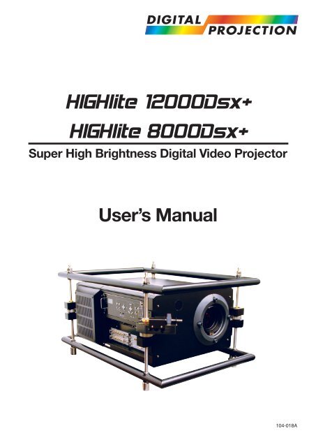
HIGHlite <strong>12000Dsx</strong>+<br />
HIGHlite <strong>8000Dsx</strong>+<br />
Super High Brightness <strong>Digital</strong> Video Projector<br />
User’s Manual<br />
E-1<br />
104-018A
Declaration of Conformity<br />
Directives covered by this Declaration<br />
89/336/EEC Electromagnetic Compatibility Directive, amended by 92/31/EEC & 93/68/EEC.<br />
73/23/EEC Low Voltage Equipment Directive, amended by 93/68/EEC.<br />
Products covered by this Directive<br />
Large Screen Projector type HIGHlite <strong>12000Dsx</strong> +<br />
HIGHlite <strong>8000Dsx</strong> +<br />
Basis on which Conformity is being declared<br />
The products identified above comply with the protection requirements of the above EU<br />
directives, and the manufacturer has applied the following standards:-<br />
EN55022:1998 - Limits and Methods of Measurements of Radio Disturbance Characteristics of<br />
Information Technology Equipment.<br />
EN 55024:1998 - Limits and Methods of Immunity Characteristics of Information<br />
Technology Equipment.<br />
EN 61000-3-2:2000 - Harmonic Current Emissions.<br />
EN 61000-3-3:1995 - Immunity to Voltage Fluctuations and Flicker.<br />
The technical documentation required to demonstrate that the products meet the requirements<br />
of the Low Voltage directive has been compiled by the signatory below and is available for<br />
inspection by the relevant enforcement authorities. The CE mark was first applied in July 2004.<br />
Signed:<br />
Authority: D.J. Quinn, Director - Product Development<br />
Date: 26 July 2004<br />
Attention!<br />
The attention of the specifier, purchaser, installer, or user is drawn to special measures and limitations<br />
to use which must be observed when these products are taken into service to maintain compliance<br />
with the above directives. Details of these special measures are available on request, and are also<br />
contained in the product manuals.<br />
E-2
Important Information<br />
CAUTION: To turn off the main power, be sure to remove the<br />
plug from power outlet. The power outlet socket should be<br />
installed as near to the equipment as possible, and should be<br />
easily accessible.<br />
3. GSGV Acoustic Noise Information Ordinance:<br />
The sound pressure level is less than 70 dB(A) according to ISO<br />
3744 or ISO 7779.<br />
WARNING<br />
TO PREVENT FIRE OR SHOCK HAZARDS, DO NOT EX-<br />
POSE THIS UNIT TO RAIN OR MOISTURE. ALSO DO NOT<br />
USE THIS UNIT’S POLARIZED PLUG WITH AN EXTENSION<br />
CORD RECEPTACLE OR OTHER OUTLETS, UNLESS THE<br />
PRONGS CAN BE FULLY INSERTED. REFRAIN FROM<br />
OPENING THE CABINET AS THERE ARE HIGH-VOLTAGE<br />
COMPONENTS INSIDE. REFER SERVICING TO QUALI-<br />
FIED SERVICE PERSONNEL.<br />
Precautions: Please read this manual carefully before using<br />
your HIGHlite <strong>12000Dsx</strong>+ HIGHlite <strong>8000Dsx</strong>+ Projector<br />
and keep the manual handy for future reference.<br />
WARNING<br />
This is a Class A product. In a domestic environment this product<br />
may cause radio interference in which case the user may be<br />
required to take adequate measures.<br />
AVERTISSEMENT<br />
POUR EVITER UN FEU OU UN RISQUE<br />
D’ELECTROCUTION NE PAS EXPOSER CET ENSEMBLE<br />
A LA PLUIE OU A L’HUMIDITE; DE MEME, NE PAS<br />
BRANCHER LA PRISE POLAIRE AVEC UNE RALLONGE A<br />
MOINS QUE LES DENTS DE LA PREMIERE NE S’Y<br />
INSERENT PLEINEMENT. EVITER D’OUVRIR LE COFFRET<br />
CAR IL Y A, A L’INTERIEUR, DES COMPOSANTS SOUMIS<br />
A UNE HAUTE-TENSION; POUR LES REPARATIONS,<br />
S’ADRESSER A UN PERSONNEL QUALIFIE.<br />
CAUTION<br />
RISK OF ELECTRIC SHOCK<br />
DO NOT OPEN<br />
ATTENTION<br />
RISQUE D’ELECTROCUTION<br />
NE PAS OUVRIR<br />
CAUTION:<br />
TO REDUCE THE RISK OF ELECTRIC SHOCK,<br />
DO NOT OPEN COVER. NO USER-SERVICE-<br />
ABLE PARTS INSIDE. REFER SERVICING TO<br />
QUALIFIED SERVICE PERSONNEL.<br />
This symbol warns the user that uninsulated voltage<br />
within the unit may have sufficient magnitude<br />
to cause electric shock. Therefore, it is dangerous<br />
to make any kind of contact with any part<br />
inside of this unit.<br />
This symbol alerts the user that important literature<br />
concerning the operation and maintenance<br />
of this unit has been included. Therefore, it should<br />
be read carefully in order to avoid any problems.<br />
ATTENTION: POUR EVITER LES RISQUES<br />
D’ELECTROCUTION, NE PAS OUVRIR LE<br />
COUVERCLE. AUCUN DES ELEMENTS IN-<br />
TERNES NE DOIT ETRE REPARE PAR<br />
L’UTILISATEUR. NE CONFIER L’ENTRETIEN<br />
QU’A UN PERSONNEL QUALIFIE.<br />
L’éclair fléché dans un triangle équilatéral est<br />
destiné à avertir l’utilisateur de la présence, dans<br />
l’appareil, d’une zone non-isolée soumise à une<br />
haute-tension dont l’intensité est suffisante pour<br />
constituer un risque d’electrocution.<br />
Le point d’exclamation dans un triangle<br />
équilatéral est destiné à attirer l’attention de<br />
l’utilisateur sur la présence d’informations de<br />
fonctionnement et d’entretien importantes dans<br />
la brochure dccompagnant l’appareil.<br />
DOC compliance Notice<br />
This Class A digital apparatus meets all requirements of the Canadian<br />
Interference-Causing Equipment Regulations.<br />
DOC avis de conformation<br />
Cet appareil numérique de la classe A respecte toutes les<br />
exigences du Réglement sur le Matériel D’interférence du<br />
Canada.<br />
CAUTION<br />
* In order to reduce any interference with radio and television reception use a signal cable with ferrite core attached.Use of signal<br />
cables without a ferrite core attached may cause interference with radio and television reception.<br />
* This equipment has been tested and found to comply with the limits for a Class A digital device, pursuant to Part 15 of the FCC<br />
Rules. These limits are designed to provide reasonable protection against harmful interference when the equipment is operated<br />
in a commercial environment. This equipment generates, uses, and can radiate radio frequency energy and, if not installed and<br />
used in accordance with the installation manual, may cause harmful interference to radio communications. Operation of this<br />
equipment in a residential area is likely to cause harmful interference in which case the user will be required to correct the<br />
interference at his own expense.<br />
E-3
Important Information<br />
Important Safeguards<br />
These safety instructions are to ensure the long life of your projector<br />
and to prevent fire and shock. Please read them carefully<br />
and heed all warnings.<br />
Installation<br />
1. Place the projector on a flat, level surface in a dry area away from dust<br />
and moisture. Tilting the front of the projector up or down from level<br />
could reduce lamp life. Do not put the projector on its side when the<br />
lamp is on.<br />
Doing so may cause damage to the projector.<br />
2. Do not place the projector in direct sunlight, near heaters or heat radiating<br />
appliances.<br />
3. Exposure to direct sunlight, smoke or steam could harm internal components.<br />
4. Handle your projector carefully. Dropping or jarring your projector could<br />
damage internal components.<br />
5. Do not place heavy objects on top of the projector.<br />
6. If you wish to have the projector installed on the ceiling:<br />
a Do not attempt to install the projector yourself.<br />
b The projector must be installed by qualified technicians in order to<br />
ensure proper operation and reduce the risk of bodily injury.<br />
c In addition, the ceiling must be strong enough to support the projector<br />
and the installation must be in accordance with any local building<br />
codes.<br />
d Please consult your dealer for more information.<br />
e Do not attempt to stack projectors on the ceiling.<br />
To Dealer or Installer:<br />
To prevent the projector from falling, install it in a place and fasten<br />
it in a way with sufficient strength to support the combined<br />
weight (94 kg/ 207.3 lb) of the projector (84 kg/185.3 lb) and the<br />
lens (10 kg/22 lb) for an extended period of time as well as to<br />
withstand earthquakes.<br />
Power Supply<br />
1. The projector is designed to operate on a power supply of 2.6 KW<br />
AC200-240V 50/60Hz. Ensure that your power supply fits this requirement<br />
before attempting to use your projector.<br />
2. Handle the power cable carefully and avoid excessive bending. A damaged<br />
cord can cause electric shock or fire.<br />
3. If the projector will not be used for an extended period of time, disconnect<br />
the plug from the power outlet.<br />
4. Do not touch the power plug with wet hand. Doing so can cause electrical<br />
shock or fire.<br />
5. Do not touch the power plug during a thunder storm. Doing so can<br />
cause electrical shock or fire.<br />
Cleaning<br />
1. Unplug the projector before cleaning.<br />
2. Clean the cabinet periodically with a damp cloth. If heavily soiled, use a<br />
mild detergent. Never use strong detergents or solvents such as alcohol<br />
or thinner.<br />
3. Use a blower or lens paper to clean the lens, and be careful not to<br />
scratch or mar the lens.<br />
Fire and Shock Precautions<br />
1. Ensure that there is sufficient ventilation and that vents are unobstructed<br />
to prevent potentially dangerous concentrations of ozone and the buildup<br />
of heat inside your projector. Allow at least 8 inches (20cm) of space<br />
between your projector and a wall. Allow at least 20 inches (50 cm) of<br />
space between the ventilation outlet and object.<br />
2. Prevent foreign objects such as paper clips and bits of paper from falling<br />
into your projector. Do not attempt to retrieve any objects that might<br />
fall into your projector. Do not insert any metal objects such as a wire or<br />
screwdriver into your projector. If something should fall into your projector,<br />
disconnect it immediately and have the object removed by a<br />
qualified your service person.<br />
3. Do not place any liquids on top of your projector.<br />
4. When using a LAN cable:<br />
For safety, do not connect to the connector for peripheral device wiring<br />
that might have excessive Voltage.<br />
CAUTION: High Pressure Lamp May Explode if Improperly<br />
Handled. Refer Servicing to Qualified Service Personnel.<br />
Lamp Caution: Please read before operation<br />
Due to the lamp being sealed in a pressurized environment,<br />
there is a small risk of explosion, if not operated correctly.<br />
There is minimal risk involved, if the unit is in proper working<br />
order, but if damaged or operated beyond the recommended<br />
1000 hours, the risk of explosion increases.<br />
Please note that there is a warning system built in, that displays<br />
the following message when you reach 1000 hours of<br />
operation “The lamp has reached the end of its usable<br />
life. Please replace the lamp” When you see this message<br />
please contact your Dealer for a replacement.<br />
If the lamp does explode, smoke will be discharged from the<br />
vents located on the side of the unit. This smoke is comprised<br />
of glass in particulate form and Xenon gas, and will not cause<br />
harm if kept out of your eyes. If your eyes have been exposed<br />
to this gas, please flush your eyes out with water immediately<br />
and seek immediate medical attention. Do not rub<br />
your eyes! This could cause serious injury.<br />
WARNING:<br />
• Do not look into the lens while the projector is on. Serious<br />
damage to your eyes could result.<br />
• When main body is damaged, cooling fluids may come out<br />
of internal part.<br />
Please do not touch and drink the cooling fluid.<br />
When the cooling fluids are swallowed or contacted with<br />
your eyes, please consult with doctors immediately.<br />
CAUTION<br />
Do not unplug the power cable from the wall outlet under any<br />
one of the following circumstances. Doing so can cause damage<br />
to the projector:<br />
• While the message “Please wait a moment” appears. This<br />
message will be displayed after the projector is turned off.<br />
• Immediately after the power cable is plugged into the wall<br />
outlet (the POWER indicator has not changed to a steady<br />
orange glow).<br />
• Immediately after the cooling fan stops working (After the<br />
projector is turned off with the POWER OFF button the cooling<br />
fan continues to work for 3 minutes while the Two Digit<br />
INDICATOR “—” flashes).<br />
E-4
Important Information<br />
Recommandations importantes<br />
Ces instructions de sécurité ont pour but d’assurer une longue<br />
vie à votre projecteur et d’éviter un incendie ou une décharge<br />
électrique. Prière de les lire avec attention et de tenir compte de<br />
tous les avertissements.<br />
Installation<br />
1. Placer le projecteur sur une surface plane et de niveau dans un endroit<br />
sec et à l’abri de la poussière et des moisissures. Le fait d’incliner l’avant<br />
du projecteur vers le haut ou le bas peut réduire la durée de vie de la<br />
lampe. Ne pas placer le projecteur sur le côté lorsque la lampe est<br />
allumée.<br />
Cela pourrait endommager le projecteur.<br />
2. Ne pas exposer le projecteur aux rayons directs du soleil, ni le placer<br />
près d’un chauffage ou de dispositifs de radiation de chaleur.<br />
3. L’exposition aux rayons directs du soleil, à la fumée ou à la vapeur<br />
pourrait endommager des composants internes.<br />
4. Manipuler le projecteur avec précautions. Laisser tomber le projecteur<br />
ou lui donner des chocs pourrait endommager des composants internes.<br />
5. Ne pas poser d’objets lourds sur le dessus du projecteur.<br />
6. Si vous voulez installer le projecteur au plafond:<br />
a. N’essayez pas d’installer le projecteur vous-même.<br />
b. Le projecteur doit être installé par un technicien qualifié pour garantir<br />
une installation réussie et réduire le risque d’éventuelles blessures<br />
corporelles.<br />
c. De plus le plafond doit être suffisamment solide pour supporter le<br />
projecteur et l’installation doit être conforme aux réglementations<br />
locales de construction.<br />
d. Veuillez consulter votre revendeur pour de plus amples informations.<br />
e. Ne pas superposer les projecteurs accrochés au plafond.<br />
A l’attention du revendeur ou de l’installateur:<br />
Afin d’empêcher une chute éventuelle du projecteur, veuillez prendre<br />
en compte lors de son placement et de sa fixation de la force<br />
nécessaire pour supporter le poids total (94 kg), celui du projecteur<br />
(84 kg) et de l’objectif (10 kg), pour de longues périodes et de<br />
façon à lui permettre de résister aux tremblements de terre.<br />
projecteur. Laisser au moins 20 cm d’espace entre le projecteur et un<br />
mur. Veuillez laisser un espace libre d’au moins 50 cm (20 pouces)<br />
entre les orifices de ventilation et l’objet.<br />
2. Empêcher tous objets étrangers tels que des attaches trombones ou<br />
des morceaux de papier de tomber à l’intérieur du projecteur. Ne pas<br />
essayer de récupérer des objets qui seraient tombés dans le projecteur.<br />
Ne pas introduire d’objets métalliques tels qu’un fil ou un tournevis dans<br />
le projecteur. Si quelque-chose doit tomber dans le projecteur, le<br />
débrancher immédiatement et faire enlever l’objet par un technicien<br />
agréé.<br />
3. Ne pas poser de liquides sur le dessus du projecteur.<br />
4. Lors de l’utilisation d’un câble LAN:<br />
Pour votre sécurité, ne raccordez pas au connecteur pour périphérique<br />
externe de câble pouvant avoir une tension excessive.<br />
ATTENTION: La lampe à haute pression peut exploser si<br />
elle est manipulée incorrectement. Confier l’entretien à du personnel<br />
d’entretien qualifié.<br />
Précautions avec la lampe : lire avant l’utilisation<br />
La lampe a été scellée dans un environnement sous pression,<br />
et il y a donc un petit risque d’explosion, si elle n’est pas utilisée<br />
correctement. Le risque est minime si l’appareil est en bon<br />
ordre de marche, mais s’il est endommagé ou utilisé au-delà<br />
des 1000 heures recommandées, le risque d’explosion<br />
augmente alors.<br />
Il est à noter l’existence d’un système d’avertissement intégré,<br />
lequel affiche le message “La lampe a atteint sa durée de<br />
vie maximum, prière de la remplacer.” lorsque les 1000<br />
heures de fonctionnement sont atteintes. Lorsque ce message<br />
apparaît, prière de contacter son revendeur pour un<br />
remplacement.<br />
Si la lampe explose, de la fumée peut être produite par les<br />
fentes d’aération situées sur le côté de l’appareil. Cette fumée<br />
est composée de verre sous forme de particules et de gaz de<br />
Xenon, et n’est pas nuisible si elle est maintenue à distance<br />
des yeux. Si les yeux sont exposés à ce gaz, les rincer<br />
immédiatement à l’eau courante et consulter tout de suite un<br />
médecin. Ne pas frotter les yeux ! Cela pourrait provoquer<br />
une grave blessure.<br />
Alimentation<br />
1. Le projecteur est conçu pour fonctionner sous une tension d’alimentation<br />
de 2,6 KW CA 200-240 V 50/60 Hz. S’assurer que la tension du secteur<br />
soit conforme à ces caractéristiques avant d’utiliser le projecteur.<br />
2. Manipuler le cordon d’alimentation avec précautions et éviter des flexions<br />
excessives. Un cordon endommagé peut occasionner une<br />
décharge électrique ou un incendie.<br />
3. Si le projecteur ne doit pas être utilisé pendant une longue période,<br />
débrancher la fiche de la prise de courant.<br />
4. Ne touchez pas la prise d’alimentation avec les mains mouillées. Ceci<br />
peut causer une électrocution ou un incendie.<br />
5. Ne touchez pas la prise d’alimentation pendant les orages. Ceci peut<br />
causer une électrocution ou un incendie.<br />
Nettoyage<br />
1. Débrancher le projecteur avant de le nettoyer.<br />
2. Nettoyer régulièrement le boîtier extérieur avec un chiffon humide. S’il<br />
est très sale, utiliser un détergent doux. Ne jamais utiliser de détergent<br />
forts ou de solvants tels que de l’alcool ou du diluant.<br />
3. Utiliser un souffleur ou du papier pour objectif pour nettoyer l’objectif,<br />
et faire attention de ne pas griffer ou endommager l’objectif.<br />
Précautions contre l’incendie ou la décharge<br />
1. S’assurer qu’il y ait une ventilation suffisante et que les ouvertures ne<br />
soient pas obstruées afin d’éviter des concentrations potentiellement<br />
dangereuses d’ozone et l’accumulation de chaleur à l’intérieur du<br />
E-5<br />
AVERTISSEMENT:<br />
• Ne pas regarder dans l’objectif lorsque le projecteur est<br />
allumé. De sérieux dommages aux yeux pourraient en<br />
résulter.<br />
• Lorsque le corps principal est endommagé, du liquide de<br />
refroidissement peut s’échapper des pièces internes.<br />
Veuillez ne pas toucher ni boire le liquide de refroidissement.<br />
Si le liquide de refroidissement est ingéré ou qu’il rentre en<br />
contact avec vos yeux, consultez immédiatement un<br />
médecin.<br />
ATTENTION<br />
Ne pas débrancher le câble d’alimentation de la prise du<br />
secteur dans les circonstances suivantes car cela risque<br />
d’endommager le projecteur:<br />
• Lorsque le message “Veuillez patientez un instant“ apparaît.<br />
Ce message sera affiché après que le projecteur soit éteint.<br />
• Immédiatement après que le cordon d’alimentation électrique<br />
ait été branché sur la prise du mur (l’indicateur POWER<br />
n’est pas encore devenu orange).<br />
• Immédiatement après que le ventilateur de refroidissement<br />
de soit arrêté de fonctionner. (Après que le projecteur ait<br />
été mis hors tension à l’aide du bouton POWER OFF, le<br />
ventilateur d’aération continue à tourner durant 3 minutes<br />
tandis que le INDICATOR à deux chiffres “—” clignote).
Important Information<br />
Achtung: Um die Netzspannung komplett abzuschalten,<br />
stellen Sie sicher, daß der Netzstecker aus der Netzsteckdose<br />
gezogen wurde. Die Netzsteckdose sollte so nahe als möglich<br />
vom Gerät entfernt und leicht zugänglich sein.<br />
3. GSGV Bestimmungen bzgl. der Geräuschabgabe<br />
Der Schalldruckpegel entsprechend den Normen ISO 3744 oder<br />
ISO 7779 beträgt weniger als 70 dB (A).<br />
WARNUNG<br />
ZUR VERMEIDUNG VON FEUER UND ELEKTRISCHEN<br />
SCHLÄGEN DARF DAS GERÄT WEDER REGEN NOCH<br />
FEUCHTIGKEIT AUSGESETZT WERDEN. DER<br />
POLARISIERTE STECKER DIESES GERÄTES DARF NUR<br />
DANN IN EIN VERLÄNGERUNGSKABEL ODER IN EINE<br />
STECKDOSE EINGESTECKT WERDEN, WENN DIE<br />
STECKKONTAKTE VOLLSTÄNDIG EINGESTECKT<br />
WERDEN KÖNNEN. UNTERLASSEN SIE, DAS GERÄT ZU<br />
ÖFFNEN, DA DADURCH IM GERÄT FREILIEGENDE<br />
HOCHSPANNUNGSFÜHRENDE TEILE BERÜHRT<br />
WERDEN KÖNNEN. LASSEN SIE DEN KUNDENDIENST<br />
NUR VON HIERFÜR QUALIFIZIERTEN PERSONEN<br />
DURCHFÜHREN.<br />
ACHTUNG<br />
GEFAHR DURCH ELEKTRISCHEN<br />
SCHLAG NICHT ÖFFNEN<br />
Wichtige Sicherheitshinweise<br />
Diese Sicherheitshinweise sollen eine lange Lebensdauer Ihres<br />
Projektors sicherstellen und vor Feuer und elektrischen Schlägen<br />
schützen. Lesen Sie diese Hinweise sorgfältig durch und<br />
beachten Sie alle Warnungen.<br />
Installation<br />
1. Stellen Sie den Projektor auf eine flache, waagerechte Oberfläche in<br />
einer trockenen Umgebung, frei von Staub und Feuchtigkeit. Das<br />
Ankippen des vorderen Teils des Projektors kann die Lebensdauer der<br />
Lampe verkürzen. Den Projektor bei eingeschalteter Lampe nicht auf<br />
die Seite legen.<br />
Dies könnte den Projektor beschädigen.<br />
2. Stellen Sie den Projektor weder in direktes Sonnenlicht noch in die<br />
Nähe einer Heizung oder sonstiger Hitze abstrahlender Einrichtungen.<br />
3. Wenn das Gerät direktem Sonnenlicht, Rauch oder Dampf ausgesetzt<br />
wird, können interne Komponenten beschädigt werden.<br />
4. Behandeln Sie Ihren Projektor vorsichtig. Fallenlassen oder starkes<br />
Schütteln kann interne Komponenten beschädigen.<br />
5. Legen Sie keine schweren Gegenstände auf den Projektor.<br />
6. Wenn der Projektor an der Decke installiert werden soll:<br />
a Versuchen Sie nicht, den Projektor selbst zu installieren.<br />
b Der Projektor muss von qualifizierten Technikern installiert werden,<br />
um einen ordnungsgemäßen Betrieb sicherzustellen und die<br />
Verletzungsgefahr zu reduzieren.<br />
c Die Decke muss für das Gewicht des Projektors ausreichende<br />
Festigkeit aufweisen, und die Installation muss entsprechend den<br />
örtlichen Bauvorschriften ausgeführt werden.<br />
d Weitere Informationen erhalten Sie von Ihrem Fachhändler.<br />
e Versuchen Sie nicht, mehrere Projektoren an der Decke<br />
übereinander zu stapeln.<br />
ACHTUNG:<br />
ZUR VERMEIDUNG EINES ELEKTRISCHEN<br />
SCHLAGES ÖFFNEN SIE NICHT DAS<br />
GEHÄUSE. INNERHALB DES GEHÄUSES<br />
BEFINDEN SICH KEINE FÜR DIE BEDIENUNG<br />
DES GERÄTES ERFORDERLICHEN TEILE.<br />
LASSEN SIE DEN KUNDENDIENST NUR VON<br />
HIERFÜR QUALIFIZIERTEN PERSONEN<br />
DURCHFÜHREN.<br />
DIESES SYMBOL WARNT DEN BEDIENER,<br />
DASS INNERHALB DES GERÄTES<br />
UNISOLIERTE TEILE VORHANDEN SIND, DIE<br />
HOCHSPANNUNG FÜHREN UND DEREN<br />
BERÜHRUNG EINEN ELEKTRISCHEN<br />
SCHLAG VERURSACHEN KANN.<br />
DIESES SYMBOL MACHT DEN BEDIENER<br />
DARAUF AUFMERKSAM, DASS WICHTIGE,<br />
DEN BETRIEB UND DIE WARTUNG DES<br />
GERÄTES BETREFFENDE SCHRIFTEN<br />
BEIGEFÜGT SIND. UM IRGENDWELCHE<br />
PROBLEME ZU VERMEIDEN, SOLLTEN<br />
DIESE BESCHREIBUNGEN SORGFÄLTIG<br />
GELESEN WERDEN.<br />
WARNUNG!<br />
Dies ist eine Einrichtung der Klasse A. Diese Einrichtung kann<br />
im Wohnbereich Funkstörungen verursachen: in diesem Fall kann<br />
vom Betreiber veriangt werden, angemessene Maßnahmen<br />
durchzuführen und dafür aufzukommen.<br />
E-6<br />
Für den Händler oder Techniker:<br />
Um ein Fallen des Projektors zu verhindern, installieren Sie den<br />
Projektor an einem sicheren Ort und befestigen Sie ihn auf eine<br />
geeignete Weise, damit das Gesamtgewicht (94kg) des Projektors<br />
(84kg), der Linse (10 kg) für einen langen Zeitraum sowie im<br />
Falle eines Erdbebens getragen werden kann.<br />
Spannungsversorgung<br />
1. Der Projektor wurde für eine Netzspannung von 2,6KW 200-240 V<br />
Wechselstrom/50/60 Hz konzipiert. Stellen Sie sicher, dass die<br />
vorhandene Spannungsversorgung diesen Vorgaben entspricht, bevor<br />
Sie versuchen, Ihren Projektor zu betreiben.<br />
2. Behandeln Sie das Netzkabel vorsichtig und vermeiden Sie Knicke.<br />
Ein beschädigtes Netzkabel kann elektrische Schläge oder einen Brand<br />
verursachen.<br />
3. Wenn der Projektor über eine längere Zeit nicht benutzt wird, ziehen<br />
Sie den Stecker aus der Netzsteckdose.<br />
4. Berühren Sie nicht den Netzstecker mit feuchten Händen. Die<br />
Nichtbeachtung dessen könnte einen Stromschlag oder einen Brand<br />
zur Folge haben.<br />
5. Berühren Sie den Netzstecker nicht während eines Gewitters. Die<br />
Nichtbeachtung dessen könnte einen Stromschlag oder einen Brend<br />
zur Folge haben.<br />
Reinigung<br />
1. Trennen Sie den Projektor vor der Reinigung von der Netzsteckdose<br />
ab.<br />
2. Reinigen Sie das Gehäuse regelmäßig mit einem feuchten Tuch. Bei<br />
starker Verschmutzung verwenden Sie ein mildes Reinigungsmittel.<br />
Reinigen Sie das Gerät niemals mit starken Reinigungs- oder Lösungsmitteln<br />
wie z.B. Alkohol oder Verdünner.<br />
3. Reinigen Sie die Linse mit einer Blaseinrichtung oder einem Linsentuch.<br />
Beachten Sie dabei, dass die Linsenoberfläche weder zerkratzt noch<br />
auf andere Weise beschädigt wird.
Important Information<br />
Vorsichtsmaßnahmen zur Vermeidung von Bränden und<br />
elektrischen Schlägen<br />
1. Sorgen Sie für ausreichende Belüftung und stellen Sie außerdem sicher,<br />
dass die Lüftungsschlitze frei bleiben, damit sich innerhalb des<br />
Projektors kein Hitzestau bilden kann. Lassen Sie mindestens 20 cm<br />
Abstand zwischen Ihrem Projektor und der Wand. Der Abstand zwischen<br />
den Belüftung und anderen Gegenständen sollte mindestens 50 cm<br />
betragen.<br />
2. Vermeiden Sie, dass Fremdgegenstände wie Büroklammern und<br />
Papierschnipsel in den Projektor fallen. Versuchen Sie nicht, in den<br />
Projektor gefallene Gegenstände selbst zu entfernen. Stecken Sie keine<br />
Metallgegenstände wie einen Draht oder Schraubendreher in Ihren<br />
Projektor. Wenn etwas in den Projektor gefallen ist, müssen Sie sofort<br />
den Netzstecker ziehen und den Gegenstand von qualifiziertem<br />
Servicepersonal entfernen lassen.<br />
3. Stellen Sie keine mit Flüssigkeit gefüllten Gefäße auf Ihren Projektor.<br />
4. Wenn ein LAN-Kabel verwendet wird:<br />
Schließen Sie es aus Sicherheitsgründen nicht an den Anschluss der<br />
Peripheriegeräte-Verbindung an, das sie eine zu hohe Spannung führen<br />
könnte.<br />
VORSICHT<br />
Unter den nachfolgend aufgeführten Umständen darf das<br />
Netzkabel nicht von der Netzsteckdose abgetrennt werden,<br />
da dies Beschädigungen des Projektors verursachen könnte:<br />
• Während die Meldung “Bitte warten Sie einen Augenblick”<br />
erscheint. Diese Meldung erscheint nach dem Ausschalten<br />
des Projektors.<br />
• Direkt nach dem Anschließen des Netzkabels an eine<br />
Netzsteckdose (die POWER-Anzeige leuchtet nicht ständig<br />
orange).<br />
• Direkt nach dem Anhalten des Lüfters. (Nach dem<br />
Ausschalten des Projektors mit der POWER OFF-Taste läuft<br />
der Lüfter noch ca. 3 Minuten weiter, während die zweistellige<br />
Anzeige INDICATOR”—” blinkt).<br />
VORSICHT: Bei unsachgemäßer Handhabung kann die<br />
Hochdrucklampe explodieren. Überlassen Sie die Reparatur<br />
ausschließlich qualifiziertem Servicepersonal.<br />
Vorsichtsmaßnahmen bezüglich der Lampe: Bitte vor<br />
dem Betrieb durchlesen<br />
Aufgrund der unter Druck luftdicht verschlossenen Lampe<br />
besteht bei falscher Handhabung eine geringe<br />
Explosionsgefahr. Wenn sich das Gerät in einwandfreiem<br />
Zustand befindet, ist dieses Risiko minimal; es erhöht sich<br />
jedoch im Falle einer Beschädigung oder bei einer Benutzung<br />
über die empfohlenen 1000 Betriebsstunden hinaus. Beachten<br />
Sie bitte, dass im Gerät ein Warnsystem integriert ist, das bei<br />
Erreichen der 1000 Betriebsstunden die nachfolgende<br />
Meldung anzeigt: “Das Ende der Lampenlebensdauer ist<br />
erreicht. Bitte ersetzen Sie die Lampe”. Beauftragen Sie<br />
Ihren Händler, sofern diese Meldung auf dem Display<br />
erscheint.<br />
Im Falle einer Lampenexplosion tritt aus den seitlichen<br />
Lüftungsschlitzen des Gerätes Rauch aus. Dieser Rauch<br />
besteht aus einer ganz besonderen Form von Glas und aus<br />
Xenon-Gas. Solange dieser Rauch nicht in die Augen gelangt,<br />
bestehen keinerlei gesundheitliche Risiken.<br />
Wenn Ihre Augen dem Gas ausgesetzt worden sind, spülen<br />
Sie die Augen bitte sofort mit Wasser aus und konsultieren<br />
Sie einen Arzt.<br />
Reiben Sie die Augen nicht!<br />
Dies könnte ernsthafte Verletzungen zur Folge haben.<br />
WARNUNG:<br />
• Schauen Sie nicht in die Linse, wenn der Projektor<br />
eingeschaltet ist. Dies könnte schwere Augenverletzungen<br />
zur Folge haben.<br />
•Wenn die Haupteinheit beschädigt ist, kann Kühlflüssigkeit<br />
aus internen Komponenten austreten.<br />
Die Kühlflüssigkeit nicht berühren oder trinken.<br />
Wenn Kühlflüssigkeit geschluckt wird oder in Kontakt mit<br />
Ihren Augen kommt, konsultieren Sie bitte umgehend einen<br />
Arzt.<br />
E-7
Table of Contents<br />
1. Introduction ............................................ E-9<br />
1 What's in the Box ................................................................. E-10<br />
2 Features .................................................................................. E-11<br />
3 Getting to Know Your Projector ............................................ E-12<br />
Control Panel ............................................................................ E-13<br />
Control Terminals ...................................................................... E-14<br />
Input Terminals ......................................................................... E-15<br />
Option Boards ........................................................................... E-16<br />
4 Remote Control Features ...................................................... E-17<br />
Remote Control Precautions .................................................... E-19<br />
Remote Control Battery Installation .......................................... E-19<br />
Operating Range for Wireless Remote Control ........................ E-19<br />
Using the Remote Control in Wired Operation ......................... E-20<br />
2. Installation ............................................ E-21<br />
1 Setting Up Your Projector ...................................................... E-22<br />
Screen Size and <strong>Projection</strong> Distance ....................................... E-22<br />
Table of Throw Distances and Image Sizes for Optional Lenses ....... E-22<br />
2 Lens Shift Adjus table Range ................................................ E-23<br />
Maximum Possible Range for SL-14Z / SL-18Z / SL-25Z / SL-45Z .... E-23<br />
3 Making Connections .............................................................. E-24<br />
Connecting to the Image Input Terminals ................................. E-24<br />
Install the Option Boards and Expand the Image Input Terminals ....... E-25<br />
Connecting to a Network .......................................................... E-26<br />
Connecting the Power Cable .................................................... E-27<br />
Inserting and Removing a PC Card .......................................... E-28<br />
4 USB Memory Device or USB Memory Card Reader Support ....... E-28<br />
3. Projecting an Image (Basic Operation) .. E-29<br />
1 Turning on the Projector ........................................................ E-30<br />
2 Selecting a Source ................................................................. E-31<br />
3 Adjusting the Picture Size and Potition ............................... E-31<br />
4 Optimizing RGB Picture Automatically ................................ E-33<br />
5 Turning off the Projector ........................................................ E-33<br />
4. Convenient Features ............................. E-35<br />
1 Turning Off the Image ............................................................ E-36<br />
2 Getting the On-Line Help and Information ........................... E-36<br />
3 Lens Memory .......................................................................... E-36<br />
Ref. Adjust ................................................................................ E-55<br />
3D Reform ......................................................................... E-55<br />
Screen ............................................................................... E-56<br />
Ref. Lens Memory ............................................................. E-56<br />
Edge Blending ................................................................... E-57<br />
Lamp Mode ....................................................................... E-58<br />
Factory Default ......................................................................... E-58<br />
Projector Options ...................................................................... E-58<br />
Menu ................................................................................. E-58<br />
Setup ................................................................................. E-59<br />
LAN Mode ......................................................................... E-62<br />
Image Mode ...................................................................... E-65<br />
Setting a Password ........................................................... E-65<br />
Security ............................................................................. E-65<br />
Tools ......................................................................................... E-67<br />
Timer ................................................................................. E-67<br />
PC Card Files .................................................................... E-69<br />
Help .......................................................................................... E-69<br />
Contents ............................................................................ E-69<br />
Source Information ............................................................ E-69<br />
Projector Information ......................................................... E-70<br />
Test Pattern ............................................................................... E-71<br />
7. Maintenance ......................................... E-73<br />
1 Cleaning the Cabinet and the Lens ...................................... E-74<br />
8. Appendix ............................................... E-75<br />
1 Troubleshooting ..................................................................... E-76<br />
2 Specifications ......................................................................... E-78<br />
3 Cabinet Dimensions ............................................................... E-80<br />
4 Compatible Input Signal List ................................................. E-82<br />
5 Pin Assignment of PC CONTROL IN Connector (D-Sub 9 Pin) ..... E-83<br />
6 Pin Assignment of REMOTE IN 3 Connector (XLR connector) ..... E-83<br />
7 Pin Assignment of EXT. I/O Connector (Mini D-Sub 15 Pin) ... E-83<br />
8 Using Software Keyboard ...................................................... E-84<br />
9 Operation Using an HTTP Browser ....................................... E-84<br />
INDEX ....................................................... E-86<br />
5. Setting Up for ouble Stacking ............... E-37<br />
1 Stacking and Connecting the Projectors ............................. E-38<br />
2 Adjusting and Registering Signals to Be Projected ............ E-41<br />
3 Adjusting the Lens Shift, Zoom and Focus<br />
to Clearly Display all projected patterns .............................. E-41<br />
6. Using On-Screen Menu ......................... E-43<br />
1 Basic Menu Operation ........................................................... E-44<br />
2 List of Direct Button Combinations ...................................... E-45<br />
3 Using the USB Mouse ............................................................ E-45<br />
4 Menu Tree ................................................................................ E-46<br />
5 Menu Descriptions & Functions ........................................... E-50<br />
Source Select ........................................................................... E-50<br />
Adjust (Source) ......................................................................... E-51<br />
Picture ............................................................................... E-51<br />
Video Adjust ...................................................................... E-51<br />
Colour Management .......................................................... E-52<br />
Gamma Correction ............................................................ E-52<br />
Image Options ................................................................... E-53<br />
Option Adjust ..................................................................... E-54<br />
Lens Memory ..................................................................... E-54<br />
Signal Type ........................................................................ E-55<br />
E-8
1<br />
Introduction<br />
○ ○ ○ ○ ○ ○ ○ ○ ○ ○ ○ ○ ○ ○ ○ ○ ○ ○ ○ ○ ○ ○ ○ ○ ○ ○ ○ ○ ○ ○ ○ ○ ○ ○ ○ ○ ○ ○ ○<br />
1 What's in the Box ................................................. E-10<br />
2 Features .................................................................E-11<br />
3 Getting to Know Your Projector ............................. E-12<br />
Control Panel .................................................................................................... E-13<br />
Control Terminals ............................................................................................. E-14<br />
Input Terminals ................................................................................................. E-15<br />
Option Boards .................................................................................................. E-16<br />
4 Remote Control Features ...................................... E-17<br />
Remote Control Precautions ............................................................................ E-19<br />
Remote Control Battery Installation .................................................................. E-19<br />
Operating Range for Wireless Remote Control ................................................ E-19<br />
Using the Remote Control in Wired Operation ................................................. E-20<br />
E-9
1. Introduction<br />
1 What's in the Box<br />
Make sure your box contains everything listed. If any pieces are missing, contact your dealer.<br />
Please save the original box and packing materials if you ever need to ship your Projector.<br />
HIGHlite <strong>12000Dsx</strong>+ Projector<br />
(USA model 103-487, ROW model 103-488)<br />
HIGHlite <strong>8000Dsx</strong>+ Projector<br />
(USA model 103-757, ROW model 103-758)<br />
NOTE: The frame is not included on HIGHlite <strong>8000Dsx</strong>+.<br />
Note: USA model is fitted with Hubbel type power cable ROW model is fitted with<br />
a CEE-Form cable.<br />
Remote control (102-161) and<br />
batteries (AA2)<br />
Remote cable<br />
102-162<br />
DVI-D signal cable<br />
(102-166)<br />
User's Manual<br />
Ferrite clamp core with Band6<br />
User’s Manual CD<br />
(104-018)<br />
Important Information<br />
printed<br />
(104-019)<br />
TL Series Lens Spacer<br />
(including screws)<br />
(104-020)<br />
E-10
1. Introduction<br />
2 Features<br />
• HDTV support, suited to 3D movement and telecine, with<br />
I/P conversion<br />
I/P conversion processing using an interpolation circuit suited<br />
to 3D movement that supports HDTV and SDTV signal input<br />
as well as telecine signals permits reproduction of images having<br />
impressive definition.<br />
• Full 10 bit image processing circuit<br />
The image processing circuit features 10 bits for each color.<br />
As a result, there is complete 10 bit processing when the signal<br />
is input from the optional SDI interface slot which will provide<br />
image quality having a high tonal quality.<br />
• Equipped with 4 slots which can accommodate 4 types of<br />
interface boards<br />
This Projector is equipped with 4 slots which permit the insertion<br />
of the following 4 types of optional interface boards. Multiple<br />
interface boards of the same type can also be inserted.<br />
Connectors of the Various Boards<br />
MM-VIDEO* .... CVBS input connector (BNC), S-Video input<br />
connector (BNC 2 conductors), Component<br />
video input connector (BNC 3 conductors)<br />
MM-RGB* ....... RGB input connector (BNC 5 conductors)<br />
MM-DVI ........... DVI-D input connector (DVI-D 24 pin)<br />
MM-SDI........... SDI input connector (BNC)2, monitor output<br />
connector (BNC)<br />
• DigiWarp - Geometric Warp Correction Function<br />
In the case pictures are projected on particular shaped screens<br />
(cylindrical or spherical), geometric warp can be corrected by<br />
implementing MM-WARP (optional).<br />
• Dust Control of DMD<br />
Contamination of the DMD is prevented using a dust control<br />
system to stop the ingress of dust, oil and smoke particles in<br />
the air getting onto the DMD surface which can affect the quality<br />
of the projected image.<br />
• Fluid Cooled DMD<br />
The DMD temperature is controlled more efficiently by the use<br />
of fluid a cooling system.<br />
• Tilt and PAN Function with Stacking frame<br />
Projectors can be stacked vertically upto two high by built-in<br />
frame interface connectors.<br />
When projectors are stacked, image alignment can be adjusted<br />
for up/down tilt, left/right tilt and fine adjustment of PAN<br />
(left to right rotation).<br />
NOTE: The frame is not included on HIGHlite <strong>8000Dsx</strong>+.<br />
* When shipped from the factory this Projector is loaded with<br />
one MM-VIDEO board and one MM-RGB board.<br />
• High contrast images with DigiView - SweetVision TM function<br />
This Projector is equipped with the DigiView - SweetVision TM<br />
function which utilizes the characteristics of the human eye to<br />
provide an image quality with a sense of contrast.<br />
• LAN port is standard equipment and wireless LAN is supported<br />
Connection of a commercially available LAN cable (Ethernet<br />
cable) to the LAN port (RJ-45) permits control of this Projector<br />
from the personal computer via the LAN.<br />
• Seamless Switching Function<br />
Mounting of the MM-IMGPRO and MM-SCALING options permits<br />
the switching of signals between two input interface<br />
boards.<br />
Alpha Blending, Wipe, and Box In/Out image effects can be<br />
selected at the time of switching.<br />
• DigiBlend - Edge Blending Function<br />
When two or more projectors are used to project images lined<br />
up horizontally or vertically, a blending adjustment can be performed<br />
to make the borders of the adjacent images less conspicuous.<br />
The gamma curve that is adjusted to the input source can be<br />
set between 1.0 and 3.0, and 256 gradations can be expressed.<br />
E-11
1. Introduction<br />
3 Getting to Know Your Projector<br />
Frame<br />
Tilt Adjustment Knob<br />
Control panel<br />
(See page E-13)<br />
Remote sensor<br />
Lens (optional)<br />
Control terminals<br />
(See page E-14)<br />
Input terminals<br />
(See page E-15)<br />
Roll Adjustment Knob<br />
PAN Adjustment Knob<br />
NOTE: The frame is not included on HIGHlite <strong>8000Dsx</strong>+.<br />
Remote sensor<br />
Main power switch<br />
(See page E-30)<br />
Ventilation (inlet)<br />
Power cable<br />
Ventilation (outlet)<br />
E-12
1. Introduction<br />
Control Panel<br />
1 2 3 4 5 6<br />
9 10<br />
15 14 7 8 13 12 11<br />
1. LCD Screen<br />
The liquid crystal display screen shows the condition or the<br />
error message of the Projector.<br />
2. FOCUS (+/-) Button<br />
While pressing and holding CTL Button, pressing this button<br />
allows you to adjust the lens focus.<br />
3. ZOOM (+/-) Button<br />
While pressing and holding CTL Button, pressing this button<br />
allows you to zoom the lens in and out.<br />
4. LENS SHIFT GHFE<br />
While pressing and holding CTL Button, pressing this button<br />
allows you to adjust the lens offset by shifting the projected<br />
image position horizontally and / or vertically.<br />
5. MENU Button<br />
Displays the menu.<br />
6. SELECT GHFE (+) (–)<br />
GH : Use these buttons to select the menu of the item you<br />
wish to adjust.<br />
FE : Use these buttons to change the level of a selected menu<br />
item. A press of the E button executes the selection.<br />
7. ENTER Button<br />
Executes your menu selection and activates items selected<br />
from the menu.<br />
8. CANCEL Button<br />
Press this button to exit "Menus". Press this button to return<br />
the adjustments to the last condition while you are in the adjustment<br />
or setting menu.<br />
9. SHUTTER Button<br />
While pressing and holding CTL Button, pressing this button<br />
shuts off the light completely.<br />
10. CTL Button<br />
Press the CTL Button together with the FOCUS (+/-) Button,<br />
ZOOM (+/-) Button, LENS SHIFT GHFE and SHUTTER Button.<br />
The FOCUS (+/-), ZOOM (+/-), LENS SHIFT GHFE and<br />
SHUTTER Buttons do not function when pressed alone.<br />
11. POWER Button (ON / STAND BY)( )<br />
Use this button to turn the power on and off when the main<br />
power is supplied and the Projector is in standby mode.<br />
NOTE: To turn on or off the Projector, press and hold this button for a minimum<br />
of 1 second.<br />
12. POWER Indicator<br />
When this indicator is green, the Projector is on; when this<br />
indicator is orange, it is in standby mode.<br />
13. STATUS Indicator<br />
This indicates the status of the Projector during standby.<br />
The indicator will be lit in green at time of normal operation.<br />
When there is a fault, the indicator will be a flashing or steadily<br />
lit red.<br />
Please check the display information of the LCD screen when<br />
there is a fault.<br />
14. BACK LIGHT Switch<br />
Use this switch to turn on the back light of the LCD screen.<br />
15. LCD CONTRAST Adjustment Dial<br />
Use this dial to adjust the contrast of the LCD screen.<br />
E-13
1. Introduction<br />
Control Terminals<br />
3<br />
4<br />
10<br />
1<br />
2<br />
5<br />
6<br />
7<br />
8<br />
9<br />
1. USB Port (USB B)(Type B)<br />
Connect this port to the USB port (type A) of your PC using a<br />
USB cable.<br />
When USB cable is connected to this port, ferrite core, which<br />
attached to this equipment, is assembled to USB cable (near<br />
side of this equipment).<br />
2. USB Port (USB A)(Type A)<br />
When working on “menu”, commercially available USB mouse<br />
is connected and used. See page E-45.<br />
3. REMOTE IN 1 (Mini Jack)<br />
Wired remote control input.<br />
4. REMOTE OUT (Mini Jack)<br />
For Daisy-chaining multiple projectors and operating them with<br />
the same remote control. To do so, connect to a second<br />
projector’s IN terminal to relay the input at the IN terminal of<br />
the first projector until all the projectors are connected.<br />
When Remote Control Cable is connected to this port, ferrite<br />
core, which attached to this equipment, is assembled to Remote<br />
Control Cable (near side of this equipment).<br />
5. LAN Port (RJ-45)<br />
This port is typically used for UTP Ethernet/Fast Ethernet. Use<br />
this connector to control the Projector on a LAN. See page E-<br />
26.<br />
6. PC CARD Slot<br />
Insert a PC card, commercially available flash memory card or<br />
optional wireless LAN card here.<br />
7. PC CONTROL IN (D-Sub 9 Pin)<br />
Connect to the external equipment such as a PC or control<br />
system.<br />
See page E-83 for information about the pin assignment of<br />
this connector.<br />
8. PC CONTROL OUT (D-Sub 9 Pin)<br />
This connector is for future extension.<br />
9. EXT. I/O (Mini D-Sub 15 Pin)<br />
It is used when controlling the Projector from the external device<br />
equipped with a parallel interface.<br />
See Page E-83 for information about the functions and logic<br />
table of the various pins.<br />
10. REMOTE IN 2 (XLR connector)<br />
Using an extension cable such as an audio cable, permits remote<br />
control input.<br />
See page E-83 for information about the pin assignment of<br />
this connector.<br />
E-14
1. Introduction<br />
Input Terminals<br />
1<br />
3<br />
2<br />
4<br />
1. SLOT 1 (MM-VIDEO)<br />
MM-VIDEO interface board is standard equipment.<br />
2. SLOT 2 (MM-RGB)<br />
MM-RGB interface board is standard equipment.<br />
(1) (2) (3) (4)<br />
(1)<br />
(2)<br />
(3)<br />
(1) CVBS Input Connector (BNC Type)<br />
Use a 75 Ω coaxial cable and connect it to the Composite<br />
Video output connector of a DVD player, or to other equipment.<br />
(2) S-VIDEO Input Connectors (2 BNC Type)<br />
Use a 75 Ω coaxial cable (2-conductor type) and connect it to<br />
the S-Video output connector of a DVD player, or to other equipment.<br />
(3) COMPONENT Input Connectors (3 BNC Type)<br />
Use a 75 Ω coaxial cable (3-conductor type) and connect it to<br />
the Component output connector of a DVD player, or to other<br />
equipment. Standard definition only (525/60i, 625/50i).<br />
(4) ACT Indicator<br />
Steady green light ..... Shows that this board is selected.<br />
(1) RGB Input Connectors (5 BNC Type)<br />
Use a 75 Ω coaxial cable (5-conductor type) and connect it to<br />
the display output connector of a personal computer, the colour<br />
difference output connector of a Analog HDTV player, or to<br />
other equipment.<br />
When cable is connected to this port, ferrite core, which attached<br />
to this equipment, is assembled to the both sides of<br />
cable.<br />
(2) Audio Input Jacks (RCA-Phono)<br />
These Jacks have no function with the Switcher.<br />
(3) ACT Indicator<br />
Steady green light ..... Shows that this board is selected.<br />
3. SLOT 3<br />
Use to extend the input terminal. See page E-25.<br />
4. SLOT 4<br />
Use to extend the input terminal. See page E-25.<br />
NOTE: MM-VIDEO interface board and MM-RGB interface board are also available as an option.<br />
E-15
1. Introduction<br />
Option Boards<br />
MM-DVI Interface Board (Option)<br />
The DVI digital signal input board is available as an option.<br />
MM-SDI Interface Board (Option)<br />
The SDI signal input board is available as an option.<br />
(1) (2) (3)<br />
(1) (2) (3) (4)<br />
(1) DVI-D Input Connector (DVI-D 24 Pin)<br />
Use a DVI-D Signal cable and connect it to the DVI output<br />
connector of a computer.<br />
When cable is connected to this port, ferrite core, which attached<br />
to this equipment is assembled to the cable (the side<br />
ferrite core is not attached).<br />
(2) AUDIO Input Connector (Stereo Mini Jack)<br />
This jack has no function with the Projector.<br />
(3) ACT Indicator<br />
Steady green light ..... Shows that this board is selected.<br />
When Viewing a DVI <strong>Digital</strong> Signal:<br />
To project a DVI digital signal, be sure to connect the PC and<br />
the Projector using a DVI-D signal cable before turning on your<br />
PC or Projector. Turn on the Projector first and select DVI (DIGI-<br />
TAL) from the source menu before turning on your PC.<br />
Failure to do so may not activate the digital output of the graphics<br />
card resulting in no picture being displayed. Should this<br />
happen, restart your PC.<br />
Do not disconnect the DVI-D signal cable while the Projector<br />
is running. If the signal cable has been disconnected and then<br />
re-connected, an image may not be correctly displayed. Should<br />
this happen, restart your PC.<br />
(1) STATUS Indicator<br />
Steady green light ... Shows that a signal is present.<br />
Steady red light ....... Shows that there is no signal or an error<br />
occurs.<br />
(2) SDI 1 and SDI 2 Input Connectors (BNC type)<br />
Use a 75 Ω coaxial cable and connect it to a video server or<br />
video equipment.<br />
(3) MONITOR OUT Connector (BNC type)<br />
Outputs the signal from the SDI 1 or SDI 2 input you currently<br />
select.<br />
Connect this with a dedicated monitor and use it for checking<br />
the input signal.<br />
Use a 75 Ω coaxial cable.<br />
(4) ACT Indicator<br />
Steady green light ..... Shows that this board is selected.<br />
NOTE:<br />
• Use the 75 Ω coaxial (5C-2V) cable or equivalent. Higher quality recommended.<br />
Using a thinner cable than the above can degrade image quality or cause no<br />
image.<br />
• For details about the compatible input signals, see page E-82.<br />
NOTE:<br />
• Use the DVI-D signal cable compliant with DDWG (<strong>Digital</strong> Display Working<br />
Group) DVI (<strong>Digital</strong> Visual Interface) revision 1.0 standard. The DVI-D cable<br />
should be within 5 m (196") long.<br />
• For details about the compatible input signals, see page E-82.<br />
E-16
1. Introduction<br />
4 Remote Control Features 1. POWER ON<br />
Press and hold this button for a minimum of 1 second to turn<br />
on the Projector when the main power is supplied and the Projector<br />
is in standby mode.<br />
2<br />
1<br />
4<br />
5<br />
6<br />
7<br />
8<br />
10<br />
9<br />
14<br />
15<br />
19<br />
20<br />
24<br />
23<br />
ON<br />
OFF<br />
POWER<br />
ON OFF<br />
TEST<br />
IMAGE/ PROJECTOR<br />
PICTURE WHITE BAL.<br />
AUTO<br />
UNDO<br />
ADJUST<br />
CANCEL<br />
INPUT<br />
1 ABC 2 DEF 3 GHI<br />
4 JKL 5 MNO 6 PQR<br />
7 STU 8 VWX<br />
KEY ST./ R AMP/ G E-LIST/ B<br />
0<br />
HELP<br />
ENTER<br />
9 YZ/<br />
INFO<br />
PIXEL POSI/ LENS PICT/ SHUT SOUND OSD<br />
MENU/ ADDRESS<br />
MUTE<br />
FOCUS + MAGNIFY/ ZOOM +<br />
3<br />
11<br />
12<br />
13<br />
18<br />
17<br />
16<br />
21<br />
22<br />
2. POWER OFF<br />
Press and hold this button for a minimum of 1 second to turn<br />
off the Projector.<br />
3. Source / Input<br />
Press to select input or to name a signal.<br />
1 Selects the input connector of Slot 1 (MM-VIDEO at time of factory<br />
shipping).<br />
Each press of “1” button switches the input connector one step in<br />
the sequence of CVBS → S-Video → Component → CVBS → ...<br />
2 Selects the input connector of Slot 2 (MM-RGB at time of factory<br />
shipping).<br />
3 Selects the input connector of Slot 3. Becomes valid when an option<br />
board has been inserted.<br />
4 Selects the input connector of Slot 4. Becomes valid when an option<br />
board has been inserted.<br />
* The aforementioned operation is for the Projector in the factory<br />
shipping condition. The operation will differ depending on the insertion<br />
of interface boards.<br />
* When multiple input connectors are available for a single slot, pressing<br />
the number buttons that correspond to that slot will switch the<br />
input connectors within that board.<br />
NOTE: While pressing and holding CTL, pressing this button switches to the<br />
selected signal found in the Entry List.<br />
27<br />
CTL<br />
-<br />
-<br />
26<br />
25<br />
4. TEST<br />
Press to display the test pattern. Pressing this button sequentially<br />
selects test patterns.<br />
5. Backlight Switch<br />
When using the remote control wirelessly:<br />
Tums the backlight on and off. If no button operation is made<br />
within 30 seconds with the Backlight ON, the Backlight will<br />
turn off to conserve battery life.<br />
When using as the wired remote control:<br />
The light stays on in standby and power-on.<br />
YZ/<br />
9<br />
0<br />
HELP<br />
B<br />
PICT/ SH<br />
AMP/ G<br />
POSI/ LENS<br />
KEY ST./ R E-LIST/<br />
XEL<br />
6. IMAGE/PROJECTOR<br />
Press to display the Image Option screen. Pressing this button<br />
sequentially selects Image Options screens.<br />
While pressing and holding CTL, pressing this button rotates<br />
Projector Options screens.<br />
5 PQR<br />
6<br />
4 MNO<br />
POWER INPUT<br />
1 2 DEF 3 GHI<br />
ABC<br />
7 VWX<br />
8<br />
28<br />
29<br />
JKL<br />
OFF<br />
STU<br />
ON<br />
IMAGE/ PROJECTOR<br />
TEST<br />
WHITE BAL.<br />
PICTURE<br />
ADJUST<br />
ON<br />
OFF<br />
7. ADJUST PICTURE<br />
Press to display the Picture adjustment screen. Pressing this<br />
button sequentially selects adjustment screens.<br />
8. ADJUST WHITE BAL.<br />
Press to display the Color Management screen.<br />
9. KEYSTONE<br />
• 3D Reform adjustment screen is shown. See page E-xx<br />
• When optional MM-WARP is used, KEYSTONE screen and<br />
Cornerstone screen will be switched one another each time<br />
KEYSTONE button is pressed.<br />
• When KEYSTONE button is pressed for more than 2 seconds,<br />
3D Reform’s adjustment value will be bach to factory<br />
default setting.<br />
10. AMPLITUDE<br />
Service personnel only.<br />
E-17
1. Introduction<br />
11. ENTRY LIST<br />
Press to display the Entry List screen.<br />
Pressing and holding CTL and then ENTRY LIST buttons simultaneously,<br />
enters a signal in the Entry List.<br />
12. HELP<br />
Provides online help.<br />
13. INFO<br />
Displays the "Source Information" or "Projector Information"<br />
window. This button toggles between these two windows.<br />
14. PIXEL<br />
Displays the Position/Clock screen to adjust the clock and<br />
phase.<br />
15. POSITION<br />
Press to display the Position screen; press again to display<br />
the Blanking screen.<br />
16. MUTE PICTURE<br />
Press to turn off the picture for a short period of time. Press<br />
again to restore the picture.<br />
17. MUTE SOUND<br />
This button has no function with the Projector.<br />
18. MUTE OSD<br />
Press to turn off the on-screen display. Press again to restore<br />
the on-screen display.<br />
NOTE: You can also turn off the on-screen display forcibly by pressing and<br />
holding CTL and then pressing MUTE OSD (Forced On-Screen Mute Mode) ;<br />
doing this again restores it. In this case any adjustment will still change the<br />
Projector's memory settings. This mode is available even when input is switched<br />
to another or the power is turned off the main power.<br />
19. AUTO (RGB only)<br />
Press to adjust Position-H/V and Pixel Clock for an optimal<br />
picture.<br />
20. MENU<br />
Press to display the main menu.<br />
While pressing and holding CTL, press this button to display<br />
the Remote Control ID dialog box to specify the remote control<br />
ID. See page E-61.<br />
21. Select (Up/Down/Left/Right)<br />
GH: Use these buttons to select the menu of the item you<br />
wish to adjust.<br />
22. ENTER<br />
Executes the menu selection and activates items selected from<br />
the menu. When the slider or dialog box is displayed:<br />
Pressing this button confirms adjustments/setting and returns<br />
to the previous menu display.<br />
In seamless switching functions in which an option board has<br />
been mounted, press the ENTER button after the input signal<br />
switching preparation has been completed to finalize the switching.<br />
See Page E-65 for information about the seamless switching<br />
function.<br />
23. CANCEL<br />
Press to exit the menu.<br />
Press this button with CTL to return to the previous menu without<br />
closing adjustment/setting screen while the menus appear.<br />
This feature allows you to adjust or set several items concurrently.<br />
24. UNDO<br />
Press to return the adjustments and settings to the previous<br />
condition. While pressing and holding CTL, pressing this button<br />
clears the entire menus or adjustment/setting screen. At<br />
this time the adjustments/settings are stored in memory except<br />
the items on the setting screen with "OK" and "Cancel"<br />
buttons such as the Menu and the Setup screen.<br />
25. FOCUS (+/–)<br />
While pressing and holding CTL, pressing this button allows<br />
you to adjust the lens focus.<br />
26. MAGNIFY/ZOOM (+/–)<br />
While pressing and holding CTL, pressing this button allows<br />
you to zoom the lens in and out.<br />
27. CTL<br />
Used in conjunction with other buttons, similar to a shift key on<br />
a computer.<br />
28. Infrared Transmitter<br />
Direct the remote control toward the remote sensor on the Projector<br />
cabinet.<br />
29. Remote Jack<br />
Connect your remote cable here for wired operation.<br />
FE: Use these buttons to change the level of a selected menu<br />
item.<br />
A press of the E button executes the selection.<br />
Pressing and holding CTL, then pressing F button works as a<br />
Back Space key in the entry screen.<br />
Pressing and holding CTL, then pressing this button moves<br />
the menu or dialog box.<br />
E-18
1. Introduction<br />
Remote Control Precautions<br />
• The remote control system may not function when direct sunlight or<br />
strong illumination strikes the remote control sensor of the main unit, or<br />
when there is an obstacle in the path.<br />
• When remote control buttons are pressed and held, Projector’s function<br />
keys may not operate.<br />
• Do not subject to strong shock.<br />
• Do not allow water or other liquid to splash on the remote control. If the<br />
remote control gets wet, wipe it dry immediately.<br />
• Avoid exposure to heat and steam.<br />
• Remove the batteries from the remote control when the remote control<br />
is not going to be used for a long period.<br />
Operating Range for Wireless Remote Control<br />
The infrared signal operates by line-of-sight up to a distance of<br />
approximately 7m (20 feet) and a 60 degree angle of the remote<br />
sensor.<br />
The Projector will not function if there are objects between the<br />
remote sensor and the remote control or if strong light falls on<br />
the remote sensor. Weak batteries will also prevent the Projector<br />
from operating properly.<br />
Remote control<br />
Remote sensor on the<br />
Projector cabinet<br />
Remote contorol<br />
Remote Control Battery Installation<br />
Installing the Remote Control Batteries<br />
When it comes time to replace the batteries, two "AA" type will<br />
be required.<br />
7m<br />
30˚<br />
30˚<br />
30˚<br />
30˚<br />
7m<br />
1. Press and open the cover.<br />
Remote sensor on the<br />
Projector cabinet<br />
7m<br />
30˚<br />
30˚<br />
7m<br />
30˚<br />
30˚<br />
Remote control<br />
Remote control<br />
2. Align and insert the batteries according to the (+) and (-) indications<br />
inside the case.<br />
NOTE: You cannot operate the Projector using the remote control if:<br />
• The remote control ID is not set to “None”.<br />
• The remote control ID is not the same as the Projector ID.<br />
See page E-61 for setting remote control ID and Projector ID.<br />
3. Replace the cover.<br />
E-19
1. Introduction<br />
Using the Remote Control in Wired Operation<br />
Connect one end of the supplied remote cable to the REMOTE IN 1<br />
mini jack and the other end to the remote jack on the remote control.<br />
NOTE: Do not use this jack for anything other than intended use.<br />
REMOTE<br />
IN 1<br />
Remote cable (supplied)<br />
E-20
2<br />
Installation<br />
○ ○ ○ ○ ○ ○ ○ ○ ○ ○ ○ ○ ○ ○ ○ ○ ○ ○ ○ ○ ○ ○ ○ ○ ○ ○ ○ ○ ○ ○ ○ ○ ○ ○ ○ ○ ○ ○ ○<br />
1 Setting Up Your Projector ...................................... E-21<br />
Screen Size and <strong>Projection</strong> Distance ............................................................... E-22<br />
Table of Throw Distances and Image Sizes for Optional Lenses ..................... E-22<br />
2 Lens Shift Adjustable Range ................................. E-23<br />
Maximum Possible Range for SL-14Z / SL-18Z / SL-25Z / SL-45Z ................. E-23<br />
3 Making Connections .............................................. E-24<br />
Connecting to the Image Input Terminals ......................................................... E-24<br />
Install the Option Boards and Expand the Image Input Terminals ................... E-25<br />
Connecting to a Network .................................................................................. E-26<br />
Connecting the Power Cable ............................................................................ E-27<br />
Inserting and Removing a PC Card .................................................................. E-28<br />
4 USB Memory Device or USB Memory Card Reader Support .. E-28<br />
E-21
2. Installation<br />
This section describes how to set up your projector and how to<br />
connect video and audio sources.<br />
1 Setting Up Your Projector<br />
Your Projector is simple to set up and use. But before you get<br />
started, you must first:<br />
Screen Size and <strong>Projection</strong> Distance<br />
Applicable lens and throw distance/ List of screen sizes<br />
1. Determine the image size<br />
2. Set up a screen or select a non-glossy white wall onto which you can<br />
project your image.<br />
3. Install the optional lens to the projector.<br />
NOTE: The lens must be installed by service personnel only.<br />
4. Connect a PC, VCR, DVD player, or other equipment.<br />
5. Connect the supplied power cable.<br />
6. Set up the projector.<br />
7. Make settings or adjustments on the projector.<br />
Separately sold Lenses and their projection distance (reference)<br />
Height<br />
(V)<br />
Screen size (Diagonal)<br />
Width (H)<br />
Formulas: Screen Width H (5:4) (m) = Screen Height V x 5/4 x 0.0254<br />
Screen Height V (5:4) (m) = Screen Width H x 4/5 x 0.0254<br />
Screen Diagonal (5:4) (m) = Screen Height V x 6.4/4 x 0.0254<br />
Screen Width H (5:4) (inch) = Screen Height V x 5/4<br />
Screen Height V (5:4) (inch) = Screen Width H x 4/5<br />
Screen Diagonal (5:4) (inch) = Screen Height V x 6.4/4<br />
Lens Unit which can be used on this equipment as standard condition.<br />
Model<br />
Number<br />
Product<br />
Code<br />
Magnifications<br />
WIDE TELE<br />
Fixing<br />
Remarks<br />
SL-14Z 103-490 1.45 1.8 – Zoom Lens<br />
SL-18Z 103-491 1.8 2.5 – Zoom Lens<br />
SL-25Z 103-492 2.5 4.5 – Zoom Lens<br />
SL-45Z 103-493 4.5 7.3 – Zoom Lens<br />
SL-07F 103-489 – – 0.73 Fixed Focus Lens<br />
Calculation Method for <strong>Projection</strong> Distance & Screen Size<br />
<strong>Projection</strong> Distance is calculated by the following method.<br />
<strong>Projection</strong> Distance (m) = Screen Width H (m) Lens Magnification<br />
When SL-14Z Lens (Magnification ratio 1.45-1.8 : 1) is used to<br />
project on the 300” screen which diagonal length aspect ratio is<br />
4:3, the projection distance will be the following.<br />
H (the screen width (m)) = Screen Size (model) 4/5 0.0254 = 6.096m<br />
Because SL-14Z Lens (Magnification ratio 1.45-1.8 : 1) is zoom<br />
lens, there are WIDE and TELE.<br />
<strong>Projection</strong> Distance of WIDE = 6.096 1.45 = 8.839m<br />
<strong>Projection</strong> Distance of TELE = 6.096 1.8 = 10.967m<br />
Therefore, 300” screen can be projected around the projection<br />
distance of 8.84m-10.97m with SL-14Z Lens.<br />
When zoom lens is used, the magnification differs according to<br />
the zoom condition.<br />
Lens<br />
Screen<br />
Size<br />
SL-14Z<br />
SL-18Z<br />
SL-25Z<br />
SL-45Z<br />
SL-07F<br />
<strong>Projection</strong> Distance for Screen Size and Each Lens<br />
Unit : m (inch)<br />
80” 100” 150” 200” 250” 300” 400” 500”<br />
2.36~2.93 2.95~3.66 4.42~5.49 5.89~7.32 7.37~9.14 8.84~10.97 11.79~14.63 14.73~18.29<br />
(92.9~115.4) (116.1~144.1) (174.0~216.1) (231.9~288.2) (290.2~359.8) (348.0~431.9) (464.2~576.0) (579.9~720.1)<br />
2.93~4.06 3.66~5.08 5.49~7.62 7.32~10.16 9.14~12.70 10.97~15.24 14.63~20.32 18.29~25.40<br />
(115.4~159.8) (144.1~200.0) (216.1~300.0) (288.2~400.0) (359.8~500.0) (431.9~600.0) (576.0~800.0) (720.1~1000.0)<br />
4.06~7.32 5.08~9.14 7.62~13.72 10.16~18.29 12.70~22.86 15.24~27.43 20.32~36.58 25.40~45.72<br />
(159.8~288.2) (200.0~359.8) (300.0~540.2) (400.0~720.1) (500.0~900.0) (600.0~1079.9) (800.0~1440.2) (1000.0~1800.0)<br />
7.32~11.87 9.14~14.83 13.72~22.25 18.29~29.67 22.86~37.08 27.43~44.50 36.58~59.33 45.72~74.17<br />
(288.1~467.3) (359.8~583.9) (540.2~876.0) (720.1~1168.1) (900.0~1459.8) (1079.9~1752.0) (1440.2~2335.8) (1800.0~2920.1)<br />
1.19 1.48 2.23 2.97 3.71 4.45 5.93 7.42<br />
(46.9) (58.3) (87.8) (116.9) (146.1) (175.2) (233.5) (292.1)<br />
CAUTION: Distance tolerance ±5%.<br />
In addition the following Lenses can be used (However, the TL<br />
Lens spacer included is required to attach these lenses is necessary.<br />
Please contact your dealer about how to mount the spacer.).<br />
Please refer to magnification ratio on the following chart to calculate<br />
the projection distance.<br />
CAUTION: Distance tolerance ±5% .<br />
Model<br />
Number<br />
Product<br />
Code<br />
Magnifications<br />
WIDE TELE<br />
Fixing<br />
Remarks<br />
TL-1ZH LA00263 1.36 2.27 – Zoom Lens<br />
TL-2Z LA00108 2.27 4.09 – Zoom Lens<br />
TL-4Z LA00109 4.09 6.36 – Zoom Lens<br />
TL-08SF LA00111 – – 0.764 Fixed Focus Lens<br />
E-22
2 Lens Shift Adjustable Range<br />
Lens Shift Adjustable Range for Desktop and Ceiling Mount Application The diagram below shows the location of the image position<br />
in the lens. The lens can be shifted within the shaded area as shown using the normal projection position as a starting point.<br />
Maximum Possible Range for SL-14Z / SL-18Z / SL-25Z / SL-45Z<br />
Parenthesized values for the ceiling mount application<br />
Up: 0.45 V (0.14 V) Right: 0.28 H (0.17 H)<br />
Down: 0.14 V (0.45 V) Left: 0.17 H (0.28 H)<br />
(H: width of projected image, V: height of projected image)<br />
For SL-07F<br />
No shift available.<br />
Maximum Possible Range for TL-1ZH / TL-2Z / TL-4Z / TL-08SF<br />
Parenthesized values for the ceiling mount application<br />
For TL-08SF<br />
No shift available.<br />
For TL-1ZH,TL-2Z, 4Z<br />
Up: 0.37 V (0.14 V) Right: 0.23 H (0.17 H)<br />
Down: 0.14 V (0.37 V) Left: 0.17 H (0.23 H)<br />
(H: width of projected image, V: height of projected image)<br />
Desktop / Front Vertical<br />
2. Installation<br />
0.17H<br />
0.28H<br />
Max. 0.45V<br />
1V<br />
0.45V<br />
(V)<br />
Normal position<br />
Ceiling / Front Vertical<br />
Normal <strong>Projection</strong><br />
position<br />
(H)<br />
0.1V<br />
Normal position<br />
Normal <strong>Projection</strong><br />
position<br />
(H)<br />
Max. 0.45V<br />
1V<br />
0.1V<br />
(V)<br />
0.45V<br />
Example for Stack<br />
0.28H<br />
0.17H<br />
Note: Shift limit diagrams above show maximum limits of lens mount not the<br />
specific cababilities of lenses.<br />
Note: For TL lenses there is a reduced shift. See ranges above.<br />
Screen center<br />
E-23
2. Installation<br />
3 Making Connections<br />
Connecting to the Image Input Terminals<br />
This Projector has two interface boards, MM-VIDEO and MM-RGB as standard equipment. See page E-11. Connect required video<br />
signals.<br />
Four interface boards can be inserted in the Projector at the same time. See Page E-25.<br />
COMPONENT<br />
HIGHlite <strong>12000Dsx</strong>+<br />
RCA(female)-to-BNC(male)<br />
adapter (not supplied)<br />
Ferrite clamp core (supplied)<br />
Component video RCA3 cable<br />
(not supplied)<br />
BNC5 cable<br />
(not supplied)<br />
AUDIO OUT<br />
L R<br />
Component<br />
Y Cb Cr<br />
PC<br />
DVD player<br />
Information for Reducing Radiation of Electromagnetic<br />
Waves<br />
To reduce unnecessary radiation of electromagnetic waves, use<br />
the supplied ferrite clamp core.<br />
• When cable is for RGB signal, ferrite core is assembled to the<br />
both side of the cable.<br />
• When cable is for DVI-D signal, ferrite core is assembled to<br />
the side where ferrite core is not attached.<br />
• When cable is for USB or Remote Control, ferrite core is assembled<br />
to the near side of this equipment.<br />
Installation Instructions<br />
1. Opne the attach the ferrite clamp core to the cable as close as possible<br />
to end that goes to the Projector.<br />
* Push the catch to open the ferrite clamp core.<br />
* Loop the cable once around the ferrite clamp core.<br />
NOTE: When cable is thick, ferrite core is assembled without making a ring.<br />
2. Close the ferrite clamp core tightly.<br />
3. Fix the supplied band to the Ethernet cable as a stopper.<br />
* Pull the end of the band to tighten it. Cut off the surplus of the band.<br />
band<br />
E-24
2. Installation<br />
Installing Additional Option Boards<br />
Four types of option boards are available for the Projector.<br />
Please purchase as required.<br />
4. Tighten the 2 screws located at right and left of the board and fasten<br />
securely.<br />
Warning<br />
Ensure main power is disconnected or by turning<br />
off the main power switch before installing or removing<br />
the board from the Projector. Failing to do<br />
so could result in electrical shock.<br />
1. Turn off the main power switch of the Projector.<br />
NOTE: The following 4 types of option boards can be inserted in the Projector.<br />
Multiple option boards of the same model can also be inserted.<br />
* MM-VIDEO(See page E-15)<br />
* MM-RGB(See page E-15)<br />
* MM-DVI(See page E-16)<br />
* MM-SDI(See page E-16)<br />
2. Use a flat-bladed screwdriver to loosen the 2 screws of the slot panel<br />
located at the input terminals portion of the Projector, then remove the<br />
screws and panel.<br />
NOTE:<br />
• Keep the removed screws and panel in a safe place.<br />
• Please do not use the Projector while the panel is disengaged. Foreign matter<br />
could enter the interior and cause breakdown.<br />
3. Insert the board into the slot.<br />
rail<br />
The example shown in the drawing is the MM-SDI board.<br />
NOTE: When inserting the board into the slot, insert it so that it moves along the<br />
rails located at the right and left of the slot. If the board is not positioned between<br />
the rails the connector will not be engaged and the board will not be<br />
operational.<br />
E-25
2. Installation<br />
Connecting to a Network<br />
With the LAN connection, you can control the Projector over the network using a computer to turn the Projector on/off, select the<br />
input and others.<br />
Example of LAN connection<br />
Server<br />
Hub<br />
Ethernet cable (not supplied)<br />
PC<br />
LAN<br />
PC<br />
PC<br />
HIGHlite <strong>12000Dsx</strong>+<br />
Using the HTTP Server function<br />
1. Configure your LAN settings such as IP address on the Projector. (See<br />
“LAN Mode” on page E-62)<br />
2. Start the Web browser on the computer connected to the network and<br />
execute HTTP server functions. (See “Operation Using an HTTP<br />
Browser” on page E-84)<br />
E-26
2. Installation<br />
Connnecting the Power Cable<br />
After making certain that the main power switch of your projector is OFF, connect the power cable to a 200 to 240 VAC three-prong<br />
outlet (grounded).<br />
Two versions of the projector are available: USA models are supplied with a Hubbel type connector, for Rest of World a CEE-Form<br />
connector is supplied.<br />
CAUTION<br />
• Please contact your dealer / distributor to perform the wiring for connection of the power cable to your projector.<br />
• Be sure to ground the equipment to ensure safety.<br />
200-240 VAC<br />
three-prong outlet<br />
To avoid electric shocks, request a professional to carry out the grounding.<br />
Be sure to perform earth connection before inserting the power plug into the wall outlet.<br />
NOTE:<br />
• When disconnecting the power plug, first set the projector to the standby mode, and then turn off the main power switch before disconnecting the power plug.<br />
Disconnecting the power plug or turning off the main power switch without first setting the projector to the standby mode may result in the values that were set with the<br />
on-screen menu and other settings not being stored within the projector.<br />
• Do not disconnect the power plug from the outlet in circumstances such as the following:<br />
* While the hourglass icon is displayed.<br />
* While a message to the effect of “Please wait a while” is displayed. (This message will be displayed if the power has been switched off.)<br />
* Immediately after the main power switch has been turned ON. (When the POWER indicator is not lit in orange, and before “Stand by” is displayed on the liquid crystal<br />
display screen.)<br />
* Immediately after the end of the cooling down period (during which the fan is running for 3 minutes after the POWER button has been switched OFF, and before “Stand<br />
by” is displayed on the liquid crystal display screen).<br />
E-27
2. Installation<br />
Inserting and Removing a PC Card<br />
NOTE:<br />
• Do not try to force the PC card into the slot.<br />
PC CARD eject button<br />
Inserting the PC Card<br />
• Hold the PC card horizontally and insert it slowly into PC card slot<br />
with its top facing up.<br />
PC Card Type<br />
The PC Card slot accepts PCMCIA Type II only.<br />
NOTE: The projector does not support FAT32 or NTFS formatted flash memory<br />
card or USB memory device.<br />
Be sure to use a flash memory card or USB memory device formatted with the<br />
FAT16 or FAT file system.<br />
To format your flash memory card or USB memory device in your comouter, refer<br />
to the document or help file that comes with your Windows.<br />
4 USB Memory Device or USB Memory Card<br />
Reader Support<br />
The projector is compatible with either a USB memory device or<br />
USB memory card reader which supports the security features.<br />
• To use a USB memory device or USB memory card reader,<br />
connect the device to the USB port (type A).<br />
• To use a USB memory device as a Protect key for Security<br />
function, select one from the Drive icons in the Security setting<br />
screen.<br />
Removing the PC Card<br />
Press the eject button slowly. The eject button card pops out a<br />
little. Press the eject button slowly again. Grasp the edges of<br />
the PC card and pull it out. Push and insert the eject button<br />
fully until it stops.<br />
NOTE: Do not eject the PC card while its data is being accessed.<br />
CAUTION: Make sure that the PC card or wireless LAN card is<br />
removed during Standby mode or with the main power off.Failure<br />
to do so may cause damage to the data on your PC card or<br />
wireless LAN card, or may cause the projector to<br />
malfunction.Should a malfunction occur, turn off the main power<br />
and turn it back on.<br />
Direction for Inserting the PC Card<br />
The PC card has a top and bottom and must be inserted into the<br />
PC card slot in a specific direction. It cannot be inserted backwards<br />
or upside-down. Attempting to force it into the slot in the<br />
wrong direction may break the internal pin and damage the card<br />
slot. Refer to the PC card's operating instructions for the proper<br />
direction of insertion.<br />
NOTE:<br />
• Some USB memory devices (brands) or USB memory card readers<br />
may not work.<br />
• You cannot use USB memory device and a USB memory card reader<br />
when connecting a USB mouse to the projector. Using a USB HUB<br />
that allows multiple USB memory devices or card readers is not supported<br />
either.<br />
• Do not do the following while the USB memory device or USB memory<br />
card reader’s access indicator is lit or flashing (while data is being<br />
accessed.) Doing so can damage your USB memory device or USB<br />
memory card in the reader. Back up your data in case it will need to be<br />
restored.<br />
* Pulling out the USB memory device or USB memory card reader<br />
from the USB port of the projector.<br />
* Pulling out the memory card from the USB memory card reader.<br />
* Turning off the main power switch or unplugging the power cable.<br />
• The drive for ”USB 1-4” is displayed only when the USB memory device<br />
or USB memory card reader is connected to the projector. The<br />
drive for “USB 1-4” may be displayed differently from the one in the<br />
USB memory card reader.<br />
• Some USB memory devices (brands) or USB memory cards cannot<br />
be used as Protect key for the projector’s Security function.<br />
E-28
3<br />
Projecting an Image<br />
(Basic Operation)<br />
○ ○ ○ ○ ○ ○ ○ ○ ○ ○ ○ ○ ○ ○ ○ ○ ○ ○ ○ ○ ○ ○ ○ ○ ○ ○ ○ ○ ○ ○ ○ ○ ○ ○ ○ ○ ○ ○ ○<br />
1 Turning on the Projector ........................................ E-30<br />
2 Selecting a Source ................................................ E-31<br />
3 Adjusting the Picture Size and Position ................. E-31<br />
4 Optimizing RGB Picture Automatically .................. E-33<br />
5 Turning off the Projector ........................................ E-33<br />
E-29
3. Projecting an Image<br />
This chapter describes how to turn on the Projector and to project<br />
a picture onto the screen.<br />
1 Turning on the Projector<br />
NOTE:<br />
• When plugging in or unplugging the supplied power cable, make sure that the<br />
main power switch is pushed to the off[O] position. Failure to do so may cause<br />
damage to the Projector.<br />
• The Projector has two power switches: main power switch and POWER button<br />
(POWER ON and OFF on the remote control)<br />
To turn on the main power to the Projector,<br />
press the Main Power switch to the<br />
ON position ( I ).<br />
2. Press the ENTER button to execute the selection.<br />
Standby<br />
Power ON<br />
ON/STAND BY<br />
POWER<br />
3. The Basic menu will be displayed in the language you have selected.<br />
POWER<br />
Steady orange<br />
light<br />
Steady green<br />
light<br />
Before you turn on your Projector, ensure that the computer or<br />
video source is turned on.<br />
Only after you press the ON/STAND BY button on the Projector<br />
cabinet or POWER ON button on the remote control for a minimum<br />
of 1 second will the power indicator turn to green and the<br />
Projector become ready to use.<br />
To close the menu, press the CANCEL button.<br />
Note on Startup screen (Menu Language Select screen)<br />
When you first turn on the Projector, you will get the Startup<br />
screen. This screen gives you the opportunity to select one of<br />
the seven menu languages: English, German, French, Italian,<br />
Spanish, Swedish and Japanese.<br />
To select a menu language, follow these steps:<br />
1. Use the SELECT G or H button to select one of the seven languages<br />
for the menu.<br />
After this has been done, you can proceed to the advanced menu<br />
operation.<br />
If you want, you can select the menu language later. See "Language"<br />
on page E-58.<br />
NOTE: To turn the Projector on by plugging in the power cable, first turn on the<br />
Main Power switch to ON and use the menu and enable the "Auto Start" feature.<br />
(See page E-60.)<br />
E-30
3. Projecting an Image<br />
2 Selecting a Source<br />
Selecting the computer or video source<br />
Using the Remote Control<br />
3 Adjusting the Picture Size and Position<br />
1. Turn on the projector<br />
2. Select your type of projector orientation.<br />
Desktop front, ceiling rear, desktop rear, and ceiling front.<br />
ON<br />
OFF<br />
POWER<br />
ON OFF<br />
TEST<br />
IMAGE/ PROJECTOR<br />
PICTURE<br />
ADJUST<br />
WHITE BAL.<br />
INPUT<br />
1 2 DEF 3 GHI<br />
ABC<br />
4 JKL 5 MNO 6 PQR<br />
7 STU 8 VWX 9 YZ/<br />
0<br />
Press the Source/Input button<br />
(1-4) to select input.<br />
1 ...... Slot 1<br />
2 ...... Slot 2<br />
3 ...... Slot 3<br />
4 ...... Slot 4<br />
KEY ST./ R AMP/ G E-LIST/ B<br />
HELP<br />
INFO<br />
PIXEL POSI/ LENS PICT/ SHUT SOUND OSD<br />
AUTO<br />
MENU/ ADDRESS<br />
MUTE<br />
3. Display the test pattern by pressing the TEST button on the remote<br />
control or using the menu.<br />
UNDO<br />
CANCEL<br />
ENTER<br />
POWER<br />
ON OFF<br />
INPUT<br />
1 2 DEF 3 GHI<br />
ABC<br />
FOCUS +<br />
MAGNIFY/<br />
ZOOM +<br />
TEST<br />
4 JKL 5 MNO 6 PQR<br />
CTL<br />
-<br />
-<br />
ON<br />
IMAGE/ PROJECTOR<br />
7 STU 8 VWX 9 YZ/<br />
OFF<br />
PICTURE<br />
WHITE BAL.<br />
0<br />
ADJUST<br />
4. Adjust the image position and the image size.<br />
NOTE: If no input signal is available, the Projector will display a blue background<br />
(factory preset).<br />
Using the menu<br />
You can also select the computer or video source using the menu.<br />
(1) Press and hold the CTL button and press the POSITION button to<br />
display the Lens Shift adjustment screen.<br />
Use the SELECT button on the remote control or the LENS SHIFT<br />
button on the projector cabinet to move the image horizontally and<br />
vertically.<br />
To close the Lens Shift adjustment screen, press the CANCEL<br />
button. See page E-23 for “Lens Shift Adjustable Range”.<br />
KEY ST./ R<br />
AMP/ G<br />
E-LIST/ B<br />
HELP<br />
INFO<br />
AUTO<br />
MUTE<br />
PIXEL POSI/ LENS PICT/ SHUT SOUND OSD<br />
MENU/ ADDRESS<br />
AUTO<br />
MUTE<br />
MENU/ ADDRESS<br />
UNDO<br />
ENTER<br />
CANCEL<br />
CTL - -<br />
FOCUS + MAGNIFY/ ZOOM +<br />
MENU/ ADDRESS<br />
UNDO<br />
ENTER<br />
CANCEL<br />
FOCUS + MAGNIFY/ ZOOM +<br />
E-31
3. Projecting an Image<br />
(2) Press and hold the CTL and press the ZOOM + or - button to adjust<br />
the image size. You can also adjust the image size by using the<br />
CTR button and the ZOOM + or - button on the projector cabinet.<br />
CANCEL<br />
FOCUS +<br />
MAGNIFY/ ZOOM +<br />
CTL<br />
-<br />
-<br />
(3) Press and hold the CTL button and press the FOCUS + or - button<br />
to obtain the best focus. You can also adjust the focus by using the<br />
CTR button and the FOCUS + or - button on the projector cabinet.<br />
CANCEL<br />
FOCUS +<br />
MAGNIFY/ ZOOM +<br />
CTL<br />
-<br />
-<br />
Geometric Correction Tool<br />
If you use a special shaped screen such as a cylindrical or<br />
spherical screen, a downloadable program, Geometric Correction<br />
Tool is available. This program (Geometric Correction<br />
Tool) enables the geometrical distortion correction of<br />
an image when projected onto a special shaped screen with<br />
the projector. Additionally, this program allows control of the<br />
projector via a computer.<br />
For additional information contact your dealer or <strong>Digital</strong> <strong>Projection</strong>:<br />
US : powerinfo@digitalprojection.com<br />
Europe : service@digitalprojection.co.uk<br />
Global : service@digitalprojection.co.uk<br />
E-32
3. Projecting an Image<br />
4 Optimizing RGB Picture Automatically<br />
Adjusting the Image Using Auto Adjust<br />
Optimizing RGB image automatically<br />
1. Press the AUTO button on the remote control to optimize an RGB image<br />
automatically.<br />
KEY ST./ R<br />
AUTO<br />
AMP/ G<br />
E-LIST/ B<br />
HELP<br />
INFO<br />
PIXEL POSI/ LENS PICT/ SHUT SOUND OSD<br />
MUTE<br />
5 Turning off the Projector<br />
To turn off the Projector:<br />
First press the POWER (ON/STAND BY) button on the Projector<br />
cabinet or the POWER OFF button on the remote control for a<br />
minimum of 1 second. The POWER indicator will glow orange.<br />
Second, turn off the Main Power switch. The power indicator will<br />
go out.<br />
Last unplug the power cable.<br />
MENU/ ADDRESS<br />
UNDO<br />
CANCEL<br />
ENTER<br />
POWER<br />
ON OFF<br />
INPUT<br />
1 2 DEF 3 GHI<br />
ABC<br />
FOCUS + MAGNIFY/ ZOOM +<br />
TEST<br />
4 JKL 5 MNO 6 PQR<br />
ON<br />
IMAGE/ PROJECTOR<br />
7 STU 8 VWX 9 YZ/<br />
The Auto Adjust menu is displayed.<br />
2. Select “Input Resolution” and change the “Horizontal” number of pixels<br />
and number of “Vertical” lines as required.<br />
OFF<br />
PICTURE<br />
ADJUST<br />
WHITE BAL.<br />
0<br />
Power on<br />
Standby<br />
POWER<br />
Steady green<br />
light<br />
ON/STAND BY<br />
POWER<br />
Steady orange<br />
light<br />
3. Align the cursor with “OK” and press the ENTER button.<br />
[Poor picture]<br />
[Normal picture]<br />
Press the AUTO button to fine-tune the computer image or to<br />
remove any vertical banding that might appear and to reduce<br />
video noise, dot interference or cross talk (this is evident when<br />
part of your image appears to be shimmering). This function adjusts<br />
the clock frequencies that eliminate the horizontal banding<br />
in the image. This function also adjusts the clock phase to reduce<br />
video noise, dot interference or cross talk. (This is evident<br />
when part of your image appears to be shimmering.)<br />
This adjustment may be necessary when you connect your computer<br />
for the first time.<br />
CAUTION<br />
• When switching off the Main Power switch, set the Projector<br />
to the standby mode beforehand. Values that have<br />
been set with the on-screen menu or by other means might<br />
not be stored in the main unit if the Projector power supply<br />
is on when the Main Power switch is switched off.<br />
• Do not unplug the power cable from the wall outlet or do<br />
not turn off the main power under any one of the following<br />
circumstances. Doing so can cause damage to the<br />
Projector:<br />
* While the Hour Glass icon appears.<br />
* While the message "Please wait a moment." appears. This message<br />
will be displayed after the Projector is turned off.<br />
* Immediately after the main power switch has been turned ON.<br />
(When the POWER indicator is not lit in orange, and before<br />
“Stand by” is displayed on the liquid crystal display screen.)<br />
* Immediately after the end of the cooling down period (during<br />
which the fan is running for 3 minutes after the POWER button<br />
has been switched OFF, and before “Stand by” is displayed on<br />
the liquid crystal display screen).<br />
NOTE:<br />
• Some signals may not be displayed correctly or take time.<br />
• The Auto Adjust function does not work for component and video signal.<br />
• If the Auto Adjust operation cannot optimize the RGB signal, try to adjust Clock<br />
and Phase manually. See page E-53.<br />
E-33
E-34
4<br />
Convenient Features<br />
○ ○ ○ ○ ○ ○ ○ ○ ○ ○ ○ ○ ○ ○ ○ ○ ○ ○ ○ ○ ○ ○ ○ ○ ○ ○ ○ ○ ○ ○ ○ ○ ○ ○ ○ ○ ○ ○ ○<br />
1 Turning Off the Image ............................................ E-36<br />
2 Getting the On-line Help and Information .............. E-36<br />
3 Lens Memory ......................................................... E-36<br />
E-35
4. Convenient Features<br />
1 Turning Off the Image<br />
3 Lens Memory<br />
Press the MUTE PICTURE button to turn off the image for a<br />
short period of time. Press again to restore the image.<br />
Press the MUTE OSD button to turn off the on-screen display.<br />
Press again to restore the on-screen display.<br />
NOTE: You can also turn off the on-screen display forcibly by pressing and holding<br />
CTL and then pressing MUTE OSD (Forced On-Screen Mute Mode) ; doing this<br />
again restores it. In this case any adjustment will still change the projector's memory<br />
settings. This mode is available even when input is switched to another or the main<br />
power is turned off.<br />
2 Getting the On-line Help and Information<br />
You get the contents about Help.<br />
KEY ST./ R<br />
AUTO<br />
AMP/ G<br />
E-LIST/ B<br />
Display Help<br />
You get the source and projector information.<br />
Press this button once to display “Source Information” and press<br />
twice to display “Projector Information”.<br />
Press third time to close it.<br />
HELP<br />
INFO<br />
PIXEL POSI/ LENS PICT/ SHUT SOUND OSD<br />
KEY ST./ R<br />
AUTO<br />
AMP/ G<br />
E-LIST/ B<br />
MUTE<br />
HELP<br />
INFO<br />
PIXEL POSI/ LENS PICT/ SHUT SOUND OSD<br />
MUTE<br />
This function serves to store the adjusted value when using the<br />
Shift, Focus, and Zoom buttons of the projector or the remote<br />
control.<br />
Reference memory:<br />
Reference Point ...... Adjusted settings are stored in memory<br />
as a reference common to all the input<br />
sources. If no setting is stored in Custom<br />
Point, the adjusted settings in Reference<br />
Point will be applied.<br />
Custom memory:<br />
Custom Point ........... Adjusted settings are stored in memory<br />
for each input signal.<br />
Usage Example<br />
When you wish to display on a screen having a 4:3 aspect ratio<br />
an NTSC or other 4:3 aspect ratio signal and an SXGA or other<br />
5:4 aspect ratio signal:<br />
Perform shift, focus, and zoom adjustments to set the vertical<br />
screen size of the vertically tall 5:4 aspect ratio signal to standard.<br />
Both 4:3 apsect ratio signals and 5:4 aspect ratio signals can<br />
now be displayed.<br />
Note that with these shift, focus, and zoom adjustments, the 4:3<br />
aspect ratio signal will become smaller on the screen.<br />
To eliminate this size reduction, adjust the shift, focus and zoom<br />
to the optimum condition for each of the 4:3 aspect ratio signal<br />
and the 5:4 aspect ratio signal. Memory (storage) of each of these<br />
values will permit projection at an optimum condition upon signal<br />
switching.<br />
1. Perform Zoom, Focus and Lens Shift adjustments and store<br />
them in memory using “Set Custom Point”.<br />
Another way to store your adjustments is to use the CTL and<br />
INFO buttons on the remote control.<br />
2. When “Yes” is selected for “Use Point on Signal Change”, the<br />
adjustment is applied to the signal you switched.<br />
3. Select “OK” and press the ENTER button for the change to<br />
take effect.<br />
Picture Mute during Lens Shift<br />
To turn off the image during lens shift, select "Yes".<br />
NOTE: This option is only available when "Yes" is selected for "Use Point on Signal<br />
Change".<br />
E-36
5<br />
Setting Up for Double Stacking<br />
○ ○ ○ ○ ○ ○ ○ ○ ○ ○ ○ ○ ○ ○ ○ ○ ○ ○ ○ ○ ○ ○ ○ ○ ○ ○ ○ ○ ○ ○ ○ ○ ○ ○ ○ ○ ○ ○ ○<br />
1 Stacking and Connecting the Projectors ............... E-38<br />
2 Adjusting and Registering Signals to Be Projected ....... E-41<br />
3 Adjusting the Lens Shift, Zoom and Focus<br />
to Clearly Display all projected patterns ................ E-41<br />
E-37
1 Stacking and Connecting the Projectors<br />
NOTE: Up to two units can be gravity stacked without external support. In some<br />
cases, however, two images will not align on the screen correctly. This will become<br />
more apparent when displaying small text and detailed graphics.<br />
NOTE: The frame is not supplied on HIGHlite <strong>8000Dsx</strong>+.<br />
5. Setting Up for Double Stacking in Link Mode<br />
Master projector<br />
Slave projector<br />
CAUTION: To prevent the projectors from falling, install them in a place and fasten them in a<br />
way with sufficient strength to support the two projectors.<br />
1-1. Frame Connection (HIGHlite<strong>12000Dsx</strong>+)<br />
Remove feet from projector to be mounted on top of stack.<br />
Master Projector<br />
2. Lift the projector of feet.<br />
Slave Projector<br />
Button<br />
Ball-lock Pin<br />
1. Press Button to<br />
remove Ball-Lock Pin<br />
E-38
5. Setting Up for Double Stacking in Link Mode<br />
Place projectors together.<br />
Master Projector<br />
Connect projectors using Ball-lock Pins.<br />
4. Insert all four Ball-lock Pins back into<br />
stacking connectors<br />
Master Projector<br />
3. Stack projectors<br />
Join using stacking<br />
connectors<br />
Slave Projector<br />
Slave Projector<br />
1-2. Frame Adjustment (HIGHlite<strong>12000Dsx</strong>+)<br />
• Tilt Angle Adjustment<br />
Knurled knobs (A, B on the<br />
picture at the left) are turned<br />
to the same direction. (note 1)<br />
Screen<br />
• Roll Angle Adjustment<br />
Knurled knobs (B, C on the<br />
picture at the left) are turned<br />
to the same direction. (note 1)<br />
Screen<br />
Knurled knob<br />
• PAN Angle Adjustment<br />
Knurled knob (S) (Enlarged<br />
picture at the left) is turned.<br />
Screen<br />
Enlarged<br />
Knurled knob(S)<br />
note 1: when Knurled knobs at two locations are turned, the same charge should<br />
be turned.<br />
1-3. Assigning Projector IDs<br />
You can operate multiple projectors with the same remote control.<br />
To do so:<br />
E-39
5. Setting Up for Double Stacking in Link Mode<br />
13-1. Select “Projector Options” → “Setup” → “Page4” → “Projector<br />
ID” and assign an ID number to each projector. See also<br />
page 8-18.<br />
1-3-3. On the remote control specify the ID number of the projector<br />
to be adjusted. Press and hold the CTL and press<br />
MENU (ADDRESS) button to enter the ID number.<br />
You can operate the projector assigned the same ID number<br />
as the remote control.<br />
NOTE: Specifying "None" for projector ID allows you to operate multiple projectors<br />
concurrently. However, some projectors may not synchronize to the other projectors.<br />
1-3-2. Select the same communication speed for both the projector.<br />
1-4. Stacking the Projectors<br />
Place the projectors at the proper height for best screen to projector<br />
relationship. Make sure that all projectors have the same<br />
display orientation.<br />
NOTE: Do not turn on [Master] or [Slave] at this time.<br />
1-5. Cable Connection<br />
Example on Video Signal<br />
Picture signal is divided by commercial signal divider, and connected to both master projector’s and slave projector’s input ports.<br />
Signal Divider<br />
According to signal dividers, the port<br />
name, location and aspect are different.<br />
Please check the signal dividers'<br />
instruction manuals.<br />
S-VIDEO<br />
INPUT<br />
S-Video cable (not supplied)<br />
S-VIDEO<br />
OUTPUT<br />
1<br />
2<br />
S-VIDEO<br />
Master projector<br />
S-Video cable<br />
(not supplied)<br />
L R VIDEO S-VIDEO<br />
AUDIO OUT VIDEO OUT<br />
Picture Device<br />
According to picture devices, the port<br />
name, location and aspect are different.<br />
Please check the picture devices'<br />
instruction manuals.<br />
S-VIDEO<br />
Slave projector<br />
E-40
5. Setting Up for Double Stacking in Link Mode<br />
1-6. Control Cable Connection<br />
Example of Remote Controllers Control<br />
Remote controller and master projector’s remote controller input 1 port (REMOTE1 IN 1 )are connected by remote cable. Master<br />
projector’s remote output port (REMOTE OUT) and slave projector’s remote controller input 1 port (REMOTE IN 1) are connected by<br />
remote cable.<br />
NOTE:<br />
• When ID is not setup for the projector and remote controller, two projectors are controlled at the same time with one remote controllers. To control two projectors<br />
indivisually, setup IDs for each projector and each remote controller.<br />
Remote cable<br />
(supplied)<br />
REMOTE<br />
IN 1<br />
REMOTE<br />
OUT<br />
Remote control<br />
Master projector<br />
Ferrite clamp core(supplied)<br />
REMOTE<br />
IN 1<br />
Remote cable(supplied)<br />
Slave projector<br />
Example of RS-232C Control<br />
The controller with RS-232C interface and each projector’s PC control-in port (PC CONTROL IN) are connected by cross cable and<br />
the individuals are controlled by serial-control-command.<br />
Please ask delivery outlets for serial-control-command.<br />
Master projector<br />
PC CONTROL<br />
IN<br />
RS-232C Cross cable<br />
(not supplied)<br />
PC<br />
or<br />
Controller<br />
PC CONTROL<br />
IN<br />
Slave projector<br />
E-41
2 Adjusting and Registering Signals to Be<br />
Projected<br />
2-1. Making Adjustments to the Master Projector<br />
2-1-1. Display a desired input signal on the master projector.<br />
2-1-2. Make adjustment to the signal, then save (register) adjustments<br />
on the master projector by pressing and holding<br />
CTL and pressing ENTRY LIST button on the remote control.<br />
2-1-3. Repeat steps 2-1-1 and 2-1-2 for all signals you want<br />
to project.<br />
Display all the signals you registered and check. To check,<br />
select “Source Select” → “Entry List”.<br />
2-2. Making Adjustments to the Slave Projector<br />
2-2-1. Display a desired input signal on the slave projector.<br />
2-2-2. Make adjustment to the signal, then save (register) adjustments<br />
on the slave projector by pressing and holding<br />
CTL and pressing ENTRY LIST button on the remote control.<br />
2-2-3. Repeat steps 2-1-2 and 2-1-2 for all signals you want<br />
to project.<br />
Display all the signals you registered and check. To check,<br />
select “Source Select” → “Entry List”.<br />
3 Adjusting the Lens Shift, Zoom and Focus<br />
to Clearly Display all projected patterns<br />
3-1. Display the internal crosshatch test pattern.<br />
NOTE: Use a different single colour for each projector. Example: Turn on Green of<br />
master projctor, then Red of the slave projector.<br />
3-2. Adjust the Lens Shift by pressing and holding CTL and pressing<br />
the POSITION button on the remote control.<br />
For lens shift adjustable range, see page E-23. Lens Shift Adjustable<br />
Range.<br />
3-3. Zoom the lens in and out by pressing and holding CTL and<br />
pressing the MAGNIFY(ZOOM)+/- button on the remote control.<br />
3-4. Adjust the lens focus by pressing and holding CTL and pressing<br />
the FOCUS +/- button on the remote control.<br />
NOTE: If the physical (vertical) alignment of the projector is not correct, adjust the<br />
height of the feet. If there is any keystone distortion, use 3D-Reform (Keystone)<br />
adjustment to correct and save the settings on each projector. See page E-55 for<br />
3D-Reform.<br />
5. Setting Up for Double Stacking in Link Mode<br />
E-42
6<br />
Using On-Screen Menu<br />
○ ○ ○ ○ ○ ○ ○ ○ ○ ○ ○ ○ ○ ○ ○ ○ ○ ○ ○ ○ ○ ○ ○ ○ ○ ○ ○ ○ ○ ○ ○ ○ ○ ○ ○ ○ ○ ○ ○ ○ ○ ○ ○ ○ ○ ○ ○ ○ ○ ○ ○ ○ ○ ○ ○ ○ ○<br />
1 Basic Menu Operation ............................. E-44<br />
2 List of Direct Button Combinations .......... E-45<br />
3 Using the USB Mouse ............................. E-45<br />
4 Menu Tree ............................................... E-46<br />
5 Menu Descriptions & Functions ............... E-50<br />
Source Select .......................................... E-50<br />
Adjust (Source) ....................................... E-51<br />
Picture ................................................ E-51<br />
Video Adjust ....................................... E-51<br />
Colour Management .......................... E-52<br />
Gamma Correction............................. E-52<br />
Image Options.................................... E-53<br />
Option Adjust...................................... E-54<br />
Lens Memory ..................................... E-54<br />
Signal Type ........................................ E-55<br />
Ref. Adjust ............................................... E-55<br />
3D Reform.......................................... E-55<br />
Screen................................................ E-56<br />
Edge Blending.................................... E-57<br />
Lamp Mode ........................................ E-58<br />
Factory Default ........................................ E-58<br />
Projector Options .................................... E-58<br />
Menu .................................................. E-58<br />
Setup.................................................. E-59<br />
LAN Mode .......................................... E-62<br />
Image Mode ....................................... E-65<br />
Setting a Password ............................ E-65<br />
Security .............................................. E-65<br />
Tools ........................................................ E-67<br />
Timer .................................................. E-67<br />
PC Card Files..................................... E-69<br />
Help ......................................................... E-69<br />
Contents............................................. E-69<br />
Source Information............................. E-69<br />
Projector Information.......................... E-70<br />
Test Pattern ............................................. E-71<br />
Ref. Lens Memory.............................. E-56<br />
E-43
6. Using On-Screen Menu<br />
1 Basic Menu Operation<br />
Using the Menus<br />
1. Press the MENU button on the remote control or the Projector cabinet<br />
to display the Basic, Advanced or Custom Menu.<br />
MENU/ ADDRESS<br />
2. Press the SELECT GH buttons on the remote control or the Projector<br />
cabinet to highlight the menu for the item you want to adjust or set.<br />
ENTER<br />
Customizing the Menu<br />
The Custom menu can be customized to meet your requirements.<br />
Selecting a menu item from the "Custom Menu Edit" list, allows<br />
you to custom tailor the menu items to your needs.<br />
1. Select "Custom Menu Edit" to display the "Custom Menu Edit" screen.<br />
2. Use the SELECT G or H buttons to highlight your selection and press<br />
the ENTER button to place a check mark next to an option.<br />
This action enables that feature. Press the ENTER button again to clear<br />
the check box.<br />
If you select an item with a solid triangle E and press the ENTER button<br />
on the remote control or the Switcher cabinet, you can enable all<br />
the items within that submenu. Also you can turn on an item within the<br />
submenu without placing a check mark on the main menu item.<br />
NOTE: Up to 12 main menu items (within Custom Menu Edit, not including<br />
submenu items) can be selected.<br />
3. In order for the changes to take effect, use the SELECT F or E button<br />
on the remote control or the Switcher cabinet to highlight "OK", then<br />
press the ENTER button. To cancel the changes, use the SELECT G<br />
or H buttons to highlight "Cancel" and press the ENTER button.<br />
To return to the factory default, select "Reset" then press the ENTER<br />
button.<br />
NOTE: Once you have selected OK on the Custom Menu Edit screen, you cannot<br />
cancel the changes on the Menu screen. However, you can reedit the menu items<br />
over again as described in the steps above.<br />
3. Press the SELECT E button or the ENTER button on the remote control<br />
or the Projector cabinet to select a submenu or item.<br />
ENTER<br />
NOTE: If the "Advanced Menu" item has been selected on the Menu mode, you get<br />
the "Change Custom menu now" upon completion of "Custom Menu" editing. In<br />
this case, selecting "Yes" then "ENTER" will close all the menus and apply the changes<br />
from the Advanced menu to the Custom Menu. If you select "No" then "ENTER"<br />
functions, then all menu items will return to the Advanced menu, but your changes<br />
will still be available within the "Custom Menu" selection. To display the previously<br />
tailored Custom Menu, select "Custom Menu" from the "Menu Mode".<br />
4. Adjust the level or turn the selected item on or off by using SELECT F<br />
or E buttons on the remote control or the Projector cabinet.<br />
The on-screen slide bar will show you the amount of increase or decrease.<br />
An item "To Advanced Menu" will be added to the bottom of the<br />
Custom Menu.<br />
Selecting this item and pressing the ENTER button will display<br />
the "Advanced Menu" features.<br />
ENTER<br />
5. Changes are stored until you adjust it again.<br />
ENTER<br />
CANCEL<br />
ENTER ........ Stores the setting or adjustments.<br />
CANCEL ...... Return to the previous screen without storing settings<br />
or adjustments.<br />
6. Repeat steps 2-5 to adjust an additional item, or press the CANCEL<br />
button on the Projector cabinet or the remote control to quit the menu<br />
display.<br />
E-44
6. Using On-Screen Menu<br />
2 List of Direct Button Combinations<br />
CTL+ Input (1-10)<br />
CTL+ ENTER (While displaying Entry list)<br />
CTL+ CANCEL<br />
CTL+ UNDO<br />
CTL+ GHFE<br />
CTL+ F (BS)<br />
CTL+ MUTE OSD<br />
CTL+ MENU (ADDRESS)<br />
CTL+ IMAGE (PROJECTOR)<br />
CTL+ KEYSTONE<br />
CTL+ AMPLITUDE<br />
CTL+ ENTRY LIST<br />
Switches to any selected signal found in the Entry List.<br />
To enable this combination, you must first assign specific remote buttons<br />
for direct input selection in the Entry Edit window.<br />
Displays the selected signal.<br />
Returns to the previous menu without closing the slidebar or dialog.<br />
Clears all menus or adjustment/setting screens. All adjustments are saved<br />
automatically.<br />
Moves the slidebar or dialog box horizontally or vertically.<br />
Deletes one letter or numeral in the entry screen.<br />
Turns off the on-screen display forcibly.<br />
Displays the remote ID entry window.<br />
Sequentially selects the Projector Options sub menu.<br />
This button has no function with the Projector.<br />
Service personnel only.<br />
Stores a signal in the Entry List.<br />
3 Using the USB Mouse<br />
Using a commercially available USB mouse gives you smooth<br />
operation.<br />
USB A<br />
Operate the Menus using the USB mouse<br />
Mouse Cursor<br />
When connecting a USB mouse to the projector, you get a<br />
mouse cursor on the screen.<br />
Unless you use your USB mouse within 10 seconds, the mouse<br />
cursor disappears.<br />
Menu Display<br />
Clicking with a mouse button displays the menu.<br />
Clicking E displays the pull-down menu. To close the menu,<br />
click anywhere in the background.<br />
HIGHlite <strong>12000Dsx</strong>+<br />
NOTE: There may be some brands of USB mouse that the projector does not support.<br />
Adjusting and Setting Display<br />
You can select a menu item and click with a mouse button to<br />
make adjustments and setting.<br />
Examples<br />
Click (or press and hold) the mouse button F or E to adjust<br />
the brightness. Or click and drag the mouse button on the slide<br />
bar horizontally to adjust it.<br />
To save the adjustments, click . This closes the menu. If<br />
you click anywhere in the background while displaying an adjustment<br />
and setting menu or dialog box, you will go to the<br />
main menu after clicking with the mouse.<br />
Clicking displays help.<br />
E-45
6. Using On-Screen Menu<br />
4 Menu Tree<br />
NOTE: The shaded item indicates the default setting.<br />
Advanced Menu<br />
Source Select<br />
Adjust (Source)<br />
Ref. Adjust<br />
Factory Default<br />
Projector Options<br />
Tools<br />
Help<br />
Test Pattern<br />
S1: Video<br />
S1: S-Video<br />
S1: Component<br />
S2: RGB<br />
S3: None<br />
S4: None<br />
Entry List<br />
Picture<br />
Video Adjust<br />
Colour Management<br />
Gamma Correction<br />
Image Options<br />
Option Adjust<br />
Lens Memory<br />
Signal Type<br />
* When the interface boards are installed at the factory.<br />
Load / Store / Cut / Copy / Paste / Edit / All Delete<br />
Brightness / Contrast / Saturation / Colour / Hue /Sharpness /Setup Level<br />
Noise Reduction Off / Low / Medium / High<br />
Colour Matrix Select Colour Matrix HDTV / SDTV<br />
Select Colour Matrix Type B-Y/R-Y / U/V / Cb/Cr /<br />
Pb/Pr / IVX<br />
Y/C Delay -15 to 15<br />
YTR Adjustment 0 to 31<br />
CTR Adjustment 0 to 31<br />
SweetVision 0 to 63<br />
Telecine<br />
Auto / 2:2 Off / Off<br />
3D Y/C Separation Off / On<br />
Vertical Detail<br />
Colour Correction Red / Green / Blue / Yellow / Magenta / Cyan / Colour Gain<br />
Colour Temperature Low ←→ High<br />
White Balance Brightness R / Brightness G / Brightness B /<br />
Contrast R / Contrast G / Contrast B<br />
Return to Reference Ok / Cancel<br />
Set Custom / Set Reference / Cancel<br />
Graphics Enhanced / Graphics / NTSC / NTSC Enhanced / PAL /<br />
SECAM2.8 / PAL / SECAM Enhanced / Gamma1.0-3.0<br />
Pixel Adjust Clock / Phase<br />
Position<br />
Horizontal / Vertical<br />
Aspect Ratio 1.25:1(5:4) / 1.33:1(4:3) / 1.78:1(16:9) / 1.85:1 /<br />
2.35:1<br />
Resolution Auto / Native<br />
Overscan 0% / 5% / 8% / 10%<br />
Synchronize Off / On / Adjust<br />
Video Filter Off / Less / More<br />
Blanking<br />
On / Off / Top / Bottom / Left / Right<br />
Input Resolution Horizontal / Vertical<br />
Input Position Horizontal / Vertical<br />
Clamp Timing Mode 0-4 / Adjust<br />
Sync Protection Upper / Lower<br />
VD Delay<br />
Adjustment / Field Invert (On/Off)<br />
Signal Level Red / Green / Blue<br />
Set Custom Point / Use Custom Point<br />
RGB / Component<br />
E-46
6. Using On-Screen Menu<br />
NOTE: The shaded item indicates the default setting.<br />
Advanced Menu<br />
Source Select<br />
Adjust (Source)<br />
Ref. Adjust<br />
Factory Default<br />
Projector Options<br />
Tools<br />
Help<br />
Test Pattern<br />
3D Reform<br />
Screen<br />
Ref. Lens Memory<br />
Edge Blending<br />
Lamp Mode<br />
Cornerstone 8 direction / close<br />
Keystone<br />
decrease ←→ increase<br />
(When MM-WARP (optional) is inserted, horizontal / vertical)<br />
Screen Type 1.25:1(5:4) / 1.33:1(4:3) / 1.78:1(16:9) / 1.85:1 / 2.35:1<br />
Position -64 to 64<br />
Set Reference Point / Use Reference Point / Return to Factory Default<br />
On / Off<br />
Gamma 1.0 to 3.0<br />
Input Resolution Horizontal / Vertical<br />
Input Position Horizontal / Vertical<br />
Adjust 65%~100% / Auto Off / On<br />
All Data (Including Entry List) / Current Signal<br />
Menu<br />
Setup<br />
Page 1<br />
Page 2<br />
Page 3<br />
Page 1<br />
Page 2<br />
Page 3<br />
Page 4<br />
Language English / Deutsch / Français / Italiano / Español / Svenska /<br />
Menu Mode Basic / Custom Menu / Advanced Menu / Service Menu<br />
Custom Menu Edit<br />
Menu Display Time Manual / Auto 5 sec / Auto 15 sec / Auto 45 sec<br />
Date Format MM/DD/YYYY / MM/DD/YYYY ddd / DD/MM/YYYY /<br />
DD/MM/YYYY ddd / YYYY/MM/DD / YYYY/MM/DD ddd /<br />
Month DD, YYYY / Month DD, YYYY ddd<br />
Date, Time Preset Date (MM/DD/YYYY (ddd) ) / Time (HH:MM)<br />
Display Select Date / Time / Input Terminal / Source Name / Projector ID / Message<br />
Menu Colour Colour / Monochrome<br />
Orientation Desktop Front / Ceiling Rear / Desktop Rear / Ceiling Front<br />
Background Blue / Black / Logo<br />
Sync Termination (RGB) Hi-Z / 75 [Ω]<br />
Signal Select RGB (RGB/Component / RGB / Component)<br />
Video (Auto/NTSC3.58/NTSC4.43/PAL/PAL-M/PAL-N/PAL60/SECAM)<br />
S-Video (Auto/NTSC3.58/NTSC4.43/PAL/PAL-M/PAL-N/PAL60/SECAM)<br />
Auto Adjust On / Off<br />
Auto Start<br />
On / Off<br />
Power Off Confirmation On / Off<br />
WARP Correction On / Off (When optional MM-WARP is used, it can choose.)<br />
Last Memory On / Off<br />
Lens shutter on during On / Off<br />
signal switching<br />
3D Sequence Set Select On / Off<br />
Communication Speed 4800 / 9600 / 19200 / 38400<br />
Projector ID Enable (1 to 64) / Disable<br />
Default Source Select Last / Auto / Select<br />
Select: Slot1-1(Video) / Slot1-2(S-Video) /<br />
Slot1-3(Component) / Slot2-1(RGB) /<br />
Slot3-1(None) / Slot4-1(None)<br />
* When the interface boards are installed at the factory.<br />
Control Panel Key Lock Enable / Disable<br />
E-47
6. Using On-Screen Menu<br />
NOTE: The shaded item indicates the default setting.<br />
Advanced Menu<br />
LAN Mode<br />
Source Select<br />
Adjust (Source)<br />
Ref. Adjust<br />
Factory Default<br />
Projector Options<br />
Tools<br />
Help<br />
Test Pattern<br />
Image Mode<br />
Password<br />
Security<br />
Status<br />
Mail<br />
LAN Card<br />
Build-in / PC Card<br />
Projector Name<br />
IP Address<br />
Subnet Mask<br />
Gateway<br />
MAC Address<br />
Advanced IP Address Automatic / Manual<br />
IP Address<br />
Subnet Mask<br />
Gateway<br />
DNS Configuration<br />
Domain Name<br />
Network Type Mode Infrastructure /<br />
802.11 Ad Hoc /<br />
Ad Hoc<br />
SSID<br />
Channel 1 to 14<br />
TX Rate Automatic / 11M /<br />
5.5M / 2M / 1M /<br />
1M-2M-Automatic<br />
WEP WEP Disable / 64 bit /<br />
128 bit<br />
Key Select Key 1 to 4<br />
Key 1 to 4<br />
DHCP Host Name option None / Request /<br />
Discover/Request<br />
Host Name<br />
Client-Identifer option None / Request /<br />
Discover/Request<br />
Use Mac Address On / Off<br />
Client-Identifer<br />
Recconect<br />
Alert Mail<br />
On/Off<br />
Sender’s Address<br />
SMTP Server Name<br />
Recipient’s Adderss 1 to 3<br />
Test Mail<br />
Seamless / Off<br />
Effect None / Wipe Down / Wipe Left /<br />
Wipe Up / Wipe Right / Box In /<br />
Box Out / Alpha Blending<br />
Speed<br />
Fast / Medium / Slow<br />
Menu<br />
Entry / Delete<br />
Logo<br />
Entry / Delete<br />
Enable / Disable<br />
Keyword<br />
Use Protect key / Read / Register / Delete<br />
Timer<br />
PC Card Files<br />
On / Off Timer<br />
Sleep Timer<br />
Execute / Exit / Logo<br />
Active / Inactive / Edit / Delete<br />
Remaining Time / Preset Time<br />
E-48
6. Using On-Screen Menu<br />
Advanced Menu<br />
Source Select<br />
Adjust (Source)<br />
Ref. Adjust<br />
Factory Default<br />
Projector Options<br />
Tools<br />
Help<br />
Test Pattern<br />
Contents<br />
Source Information<br />
Projector Information<br />
Page 1 Source Name / Input Terminal / Entry No. /<br />
Horizontal Frequency / Vertical Frequency / Sync Polarity<br />
Page 2 Signal Type / Video Type / Sync Type / Interlace / Direct Key<br />
Page 1 Serial Number / Remaining Lamp Time / Lamp Hour Meter /<br />
Projector Usage / Projector ID<br />
Page 2 Version (BIOS / Firmware / Data / FPGA)<br />
Page 3 Version (Formatter Red)<br />
(Boot App / Config / Degamma / Main App / Sequences)<br />
Page 4 Version (Formatter Green)<br />
(Boot App / Config / Degamma / Main App / Sequences)<br />
Page 5 Version (Formatter Blue)<br />
(Boot App / Config / Degamma / Main App / Sequences)<br />
Cross Hatch / Cross Hatch(Inv) / Alignment / Alignment(Inv) / Horizontal Gray Scale / Horizontal Gray Scale(Inv) /<br />
Vertical Gray Scale / Vertical Gray Scale(Inv) / Horizontal RAMP / Horizontal RAMP(Inv) / Vertical RAMP /<br />
Vertical RAMP(Inv) / Raster(0%) / Raster(25%) / Raster(50%) / Raster(75%) / Raster(100%)<br />
Red<br />
On / Off<br />
Green On / Off<br />
Blue<br />
On / Off<br />
E-49
6. Using On-Screen Menu<br />
Entering Alphanumeric Characters by Using the Menu<br />
Alphabet or numeric characters are used for your IP address or<br />
Projector name. To enter IP Address or Projector name, use the<br />
software keyboard.<br />
For using the software keyboard, see page E-84.<br />
5 Menu Descriptions & Functions<br />
Source Select<br />
Enables you to select a video source such as a VCR, DVD player<br />
or PC, etc. depending on what is connected to your inputs.<br />
Press the SELECT GH buttons on your remote control or the<br />
Projector cabinet to highlight the menu for the item you want to<br />
project.<br />
Entering Alphanumeric Characters by Using the Remote<br />
Control Numeric Buttons<br />
Input alphanumeric characters by selecting one character at a<br />
time with the numeric (Source/Input) buttons 1through 10(0) and<br />
by moving the cursor with the SELECT E button. After finishing<br />
the selection of the characters, press the ENTER button.<br />
Whenever one of the Source/Input buttons on the remote control<br />
is pressed, characters will be rotated.<br />
NOTE: When switching the signal with the “Seamless Switch” set to “On” and the<br />
option board mounted, a little while after the signal has been switched “Transition<br />
Ready” will be displayed on the LCD screen of the Projector. Please press the EN-<br />
TER button at this time. The seamless switching function will be activated.<br />
Please see Page E-65 for information about the image mode function.<br />
Entry List<br />
For example: A → B → C → 1 → A → ...<br />
NOTE: When holding and pressing the CTL button and pressing one of the Source/<br />
Input buttons, another group of characters will be rotated.<br />
For example: a → b → c → ! → a → ...<br />
The alphanumeric characters corresponding to these Source/Input<br />
buttons are as follows:<br />
Numeric buttons Press Press with CTL<br />
1 A → B → C → 1 a → b → c → !<br />
2 D → E → F → 2 d → e → f → ”<br />
3 G → H → I → 3 g → h → i → #<br />
4 J → K → L → 4 j → k → l → $<br />
5 M → N → O → 5 m → n → o → %<br />
6 P → Q → R → 6 p → q → r → &<br />
7 S → T → U → 7 s → t → u → '<br />
8 V → W → X → 8 v → w → x → (<br />
9 Y → Z → / → 9 y → z → → )<br />
0 * → , → . → 0 ; → : → + → -<br />
Displays the list of the entry signals. Use the SELECT GH buttons<br />
on your remote control or the Projector cabinet to select the<br />
signal and press the ENTER button on the remote control or the<br />
Projector cabinet to display the Entry Edit Command screen.<br />
Using the Entry List<br />
Making any adjustments to the current picture will automatically<br />
register its adjustments to the Entry List. The registered signal<br />
can be loaded any time from the Entry List.<br />
NOTE: Up to 100 presets can be registered.<br />
Entry Edit Command<br />
* If you have made an error in the input of a character, use the<br />
SELECT F button and enter the correct letter or number.<br />
NOTE: Only numbers can be entered when you use the remote control Source/<br />
Input buttons while displaying the Software Keyboard.<br />
You can edit signals on the Entry List.<br />
Load ............ Enables you to select a signal from the list.<br />
NOTE: This can be done by pressing CTL and ENTER buttons.<br />
E-50
6. Using On-Screen Menu<br />
Store ............ Enables you to store the currently projected signal.<br />
NOTE: This can be done by pressing CTL and ENTRY LIST buttons.<br />
Cut ............... Enables you to remove a selected signal from<br />
the list and place it on the "clipboard" in the Projector.<br />
Copy ............ Enables you to copy a selected signal from the<br />
list and place it on the "clipboard" in the Projector.<br />
Paste ........... Enables you to paste the signal placed on the<br />
"clipboard" to any other line of the list. To do this,<br />
select "Paste" and then select the line number<br />
you want to paste to. Last press ENTER.<br />
Edit .............. Enables you to change source names or assign<br />
the direct key.<br />
Source Name<br />
Enter a signal name. Up to 18 alphanumeric characters<br />
can be used.<br />
Input Terminal<br />
Change the input terminal.<br />
Direct key<br />
You can assign specific remote keys for direct<br />
signal input selection.<br />
Lock<br />
Set so that the selected signal cannot be deleted<br />
when "All Delete" is executed. The changes cannot<br />
be saved.<br />
Skip<br />
Set so that the selected signal will be skipped<br />
during auto search.<br />
When complete, select OK and press ENTER.<br />
To exit without storing setting, select Cancel.<br />
Select "Source Name" and press ENTER to display<br />
the Source Name Edit window. You can<br />
change source name on this window. Press [H]<br />
to display the software keyboard, which you can<br />
enter alphanumeric characters. See page E-84<br />
for the key function of the software keyboard.<br />
All Delete ..... This feature enables you to delete all the registered<br />
signals in the Entry List.<br />
The following buttons are not available for the currently projecting<br />
signals:<br />
1) The Cut and Paste buttons on the Entry Edit Command screen<br />
2) The Input Terminal button on the Entry Edit screen<br />
Adjust (Source)<br />
Picture<br />
Brightness<br />
Adjusts the brightness level or the back raster intensity.<br />
Colour<br />
Increases or decreases the colour saturation level (not available<br />
for RGB).<br />
Hue<br />
Varies the colour level from +/- green to +/-blue. The red level<br />
is used as reference. This adjustment is only valid for Video<br />
and Component inputs (not available for RGB).<br />
Sharpness<br />
Controls the detail of the image for Video (not available for<br />
RGB).<br />
Setup Level<br />
“7.5 IRE” must be chosen to project products manufactured in<br />
USA.<br />
Video Adjust (not available for RGB)<br />
Noise Reduction<br />
Select one of the three levels for reducing video noise: Low, Medium<br />
or High.<br />
NOTE: The lower the Noise Reduction level, the better the image quality by way of<br />
higher video bandwidth.<br />
Colour Matrix<br />
Select an appropriate colour matrix for your input signal, either<br />
HDTV or SDTV.<br />
Y/C Delay<br />
Adjusts Y/C delay level.<br />
YTR Adjustment<br />
Adjusts luminance transient time.<br />
CTR Adjustment<br />
Adjusts chroma transient time.<br />
Contrast<br />
Adjusts the intensity of the image according to the incoming<br />
signal.<br />
Saturation<br />
Adjust saturation at the white peak.<br />
E-51
6. Using On-Screen Menu<br />
DigiView - SweetVision<br />
The SweetVision feature provides improvement of contrast using<br />
a proprietary detail enhancement technology.<br />
This is valid when there is signal input to MM-VIDEO and to the<br />
MM-SDI (option).<br />
NOTE: This feature is not available for 480p, 576p and HDTV signals.<br />
Telecine<br />
Use 3:2 pull down correction to eliminate jitter and artifacts in<br />
video.<br />
Auto ............. For film source such as a DVD player<br />
2:2 Off ......... The telecine signal detection and compensation<br />
will be performed automatically only when the<br />
2:3 pull-down signal is input. Select this when<br />
entrance is not desired to the 2:2 pull-down signal<br />
detection mode.<br />
Off ............... For signals other than film sources<br />
NOTE: This feature is not available for 480p and 576p signals.<br />
3D Y/C Separation<br />
This option turns on or off the 3 dimension separation feature.<br />
NOTE: This feature is available for NTSC3.58 of Video signal only.<br />
Vertical Detail Correction<br />
Horizontal line on picture signal can be sharpened by increasing<br />
setting value.<br />
NOTE: This feature is not available for RGB signal.<br />
Colour Management<br />
Colour Management<br />
Setup relating to picture colour will be done.<br />
Vivid palette, pastel vision, colour temprature and white balance<br />
can be adjusted as your choice.<br />
Each set value is saved as exclusive use of projected signal set<br />
value, and also those can be saved as default value for this equipment.<br />
Colour Correction (Item relating to colour adjustment)<br />
Adjusts red, green, blue, yellow, magenta, cyan and colour gain<br />
each independently to correct the tint on whole screen.<br />
Colour Temperature (Item relating to colour adjustment)<br />
This feature adjusts the colour temperature using the slide bar.<br />
Checking "Colour Temperature" enables the colour temperature<br />
slide bar.<br />
White Balance (Item relating to colour adjustment)<br />
Press the White Balance button to access the Contrast/Brightness<br />
adjustment for each R, G, and B.<br />
Return to Reference (Item relating to colour adjustment)<br />
• Each set value of colour correction, colour temperature and<br />
white balance is reset. (Set back to this equipment’s default<br />
value)<br />
• Point the cursor to “Reset” and ENTER button is pressed, confirmation<br />
screen shows up. Point the cursor to “Confirm” and<br />
ENTER button is pressed, the set value is set back.<br />
NOTE:<br />
• Once the RESET is excuted, undo can’t be done even CANCEL on colour management<br />
screen is excuted.<br />
Set Custom (Item relating to set value memory)<br />
Each set value for colour correction, colour temperature and white<br />
balance can be saved to memory as exclusive use of currently<br />
projected signal set value. The screen is shut down after saving.<br />
Set Reference (Item relating to set value memory)<br />
Each set value for colour correction, colour temperature and white<br />
balance can be saved to memory as this equipment’s default<br />
value (the value set when reset). The screen is shut down after<br />
saving.<br />
Cancel (Item relating to set value memory)<br />
Each set value for colour correction, colour temperature and white<br />
balance screen is shut down without saving set value to memory.<br />
Each set up is set back to status before colour management<br />
screen is opened.<br />
Gamma Correction<br />
E-52<br />
Gradation of picture is selected. By doing this, dark parts can be<br />
expressed clearly.<br />
Graphics Enhanced ............. Correction fit to graphic signals<br />
is done.<br />
Graphics/NTSC ................... Corrections fit to graphic signals<br />
and NTSC signals are done.<br />
NTSC Enhanced ................. Correction fit to NTSC signals is<br />
done.<br />
PAL/SECAM2.8 ................... Gamma correction value 2.8 is<br />
corrected.
6. Using On-Screen Menu<br />
PAL/SECAM Enhanced ....... Correction fit to PAL signals and<br />
SECAM signals are done.<br />
Gamma 1.0 - 3.0 ................. Gamma value is set by 0.1 step.<br />
Image Options<br />
Pixel Adjust<br />
Displays the Clock and Phase adjustments.<br />
Clock ........... Use this item to fine tune the computer image or<br />
to remove any vertical banding that might appear.<br />
Phase .......... Use this item to adjust the clock phase or to reduce<br />
video noise, dot interference or cross talk.<br />
(This is evident when part of your image appears<br />
to be shimmering.) Use the SELECT F and E<br />
buttons to adjust the image.<br />
Use "Phase" only after the "Clock" is complete.<br />
Position<br />
Adjusts the image location horizontally and vertically using the<br />
SELECT F and E buttons.<br />
Aspect Ratio<br />
You can select the aspect ratio for input signal.<br />
Select the appropriate aspect ratio using the SELECT F or E<br />
button.<br />
NOTE:<br />
• When "Resolution" is set to "Native", this feature is not available, and the aspect<br />
ratio is set to “1.33:1 (4:3)”.<br />
Resolution<br />
This allows you to activate or deactivate the Advanced AccuBlend<br />
feature.<br />
Auto ............. Turns on the Advanced AccuBlend feature. The<br />
projector automatically reduces or enlarges the<br />
current image to fit the full screen.<br />
Native .......... Turns off the Advanced AccuBlend feature. The<br />
projector displays the current image in its true<br />
resolution.<br />
NOTE:<br />
* When "Resolution" is set to "Native", "Aspect Ratio", "Screen" and "Overscan" are<br />
not available.<br />
Overscan<br />
Select overscan percentage (0%, 5%, 8% and 10%) for signal.<br />
NOTE: When "Resolution" is set to "Native", this feature is not available, and the<br />
stored settings and adjustments are invalid.<br />
Synchronize<br />
Sets display vertical frequency to be synchronized with input signal.<br />
RGB signals only.<br />
OFF ............. Display vertical frequency - is independent of input<br />
signal - displayed picture is fixed at 75Hz.<br />
ON ............... Display vertical frequency - is synchronized with<br />
input signal. Frequency range of synchronization<br />
is from 24Hz to 96Hz.<br />
For optimum image quality - 3D Sequence Set<br />
Select should be set according to the following<br />
input types:<br />
(3D Sequence Set Select may be found in - “Projector<br />
Options” → “Setup” → “Page 3” → “3D Sequence<br />
Set Select” set up should be changed.<br />
See page E-61.)<br />
Vertical frequency of 24Hz to 75Hz, - remove the<br />
check mark “3D Sequence Set Select”.<br />
Vertical frequency of 75Hz to 96Hz, set the check<br />
mark “3D Sequence Set Select”.<br />
ADJUST ...... When a horizontal line (the edge of picture) is<br />
displayed on the screen while Synchronize is<br />
“ON” it can be removed using SELECT F E<br />
button on the remote controller.<br />
Note: Default is Synchronize ON for SDTV, HDTV, RGB 50Hz, 60Hz signals.<br />
Video Filter<br />
This function reduces video noise.<br />
Off ............... The filter is removed.<br />
Less ............. The low-pass filter is applied partially.<br />
More ............ The low-pass filter is applied fully.<br />
Blanking<br />
This feature allows you to mask any unwanted area of the screen<br />
image.<br />
Adjust the Top, Bottom, Left or Right blanking with the SELECT<br />
F or E button.<br />
Input Resolution<br />
This adjusts the resolution of the video area of the signal that is<br />
input to the resolution conversion processing section. When the<br />
resolution of the input signal cannot be detected properly with<br />
Auto Adjust, this function can be used to manually set the correct<br />
resolution.<br />
E-53
6. Using On-Screen Menu<br />
Input Position<br />
This adjusts the position of the video that is input to the resolution<br />
conversion processing section.<br />
It is the same function as “Input Position” within the “Edge Blending”<br />
screen.<br />
NOTE: When connecting with a scan converter:<br />
If an image from the scan converter is not correctly displayed, adjust to select the<br />
best level point so that the image is displayed correctly.<br />
Field Invert: (Upgrade support scheduled)<br />
This feature is used to correct diagonal lines of a non-standard<br />
interlaced signal when they appear jaggy.<br />
Invert the odd or even field of a video signal.<br />
Signal Level<br />
Option Adjust<br />
Clamp Timing<br />
According to the signal, this function sets the detection position<br />
(i.e., clamp position) of the black level reproduction of the analog<br />
input signal. Normally this is not used.<br />
Mode 0-4 ..... Select the appropriate one.<br />
Adjust .......... This permits the video clamp position for each<br />
signal to be set. Use "Adjust" when a clamp timing<br />
error occurs at the time of special analog signal<br />
reception such as 1080P. Note that "Adjust"<br />
is not valid for doubler signals such as NTSC<br />
and PAL.<br />
To delete the "Clamp Timing" setting screen, select the SELECT<br />
H button and press the ENTER button, or press the remote control<br />
CANCEL button.<br />
Sync Protection<br />
R/G/B, Y/Cb/Cr or Y/Pb/Pr Gain:<br />
Adjust RGB, Component or HDTV Gain to match multiple projector<br />
colour uniformity.<br />
Lens Memory<br />
When a VCR, DVD, or some other equipment that supports<br />
Copyguard (a copy prevention system) is played back, the screen<br />
may be displayed in a curved manner. Adjustments are made in<br />
such circumstances. Use the SELECT F or E button to adjust<br />
the VD level.<br />
VD Delay<br />
This function serves to store or apply the adjusted value when<br />
using the Shift, Focus and Zoom buttons on the projector or the<br />
remote control.<br />
Set Custom Point ........... Store the current adjusted values in<br />
memory.<br />
Use Custom Point .......... Apply the adjusted values to the current<br />
signal.<br />
NOTE:<br />
•To enable the Lens Memory feature, select [Ref. Adjust] → [Ref. Lens Memory]<br />
and place a check mark next to “Yes” for [Use Point on Signal Change].<br />
•To store adjusted values common to all the input sources, use the Ref. Lens<br />
Memory. See page E-56.<br />
Adjustment:<br />
This feature is used to correct vertical jitter of a signal.<br />
E-54
6. Using On-Screen Menu<br />
Signal Type<br />
Keystone Correction<br />
Select either the RGB signal type or the Component signal type.<br />
RGB ............ RGB signal<br />
Component .. Component signals such as Y/Cb/Cr, Y/Pb/Pr<br />
NOTE: This feature is available on RGB only. If you do not get a better picture even<br />
when you set "Signal Select" to "Component" in Setup, set this to "Component".<br />
Ref. Adjust<br />
3D Reform<br />
This feature corrects trapezoidal distortion so that the projected<br />
image is rectangular.<br />
Operation of 3D Reform is available whether MM-WARP (optional)<br />
is used or not.<br />
MM-WARP- not installed or not active<br />
When MM-WARP is not installed (optional) or installed but not<br />
active only vertical adjustment in Keystone Correction is possible.<br />
(For de-activation set no check mark on “Projector Options” →<br />
“Setup” → “page 3” → “WARP Correction”.)<br />
1. Press SELECT Button - Adjust screen size in horizontal direction.<br />
2. Press SELECT Button - Choose “Vertical”.<br />
3. Press SELECT Button - Adjust screen size in vertical direction.<br />
4. Press ENTER after adjusting screen size. - Return to the menu.<br />
Cornerstone<br />
Keystone Correction<br />
1. Project an image so that the screen is smaller than the area of the<br />
raster.<br />
2. Pick up any one of the corners and align the corner of the screen with<br />
the one of the image.<br />
Projected image<br />
1. Press SELECT Button - Adjust screen size in vertial direction.<br />
2. Press ENTER Button after adjusting screen size - Return to the menu.<br />
MM-WARP - active<br />
When MM-WARP (optional) is installed and active both vertical<br />
and horizontal adjustment in Keystone Correction is possible.<br />
(To activate set check mark on “Projector Options” → “Setup” →<br />
“page 3” → “WARP Correction”.)<br />
Screen<br />
(The drawing shows the upper right corner.)<br />
3. Use the SELECT GHFE button to select one icon which points in the<br />
direction you wish to move the projected image frame.<br />
Screen<br />
E-55
6. Using On-Screen Menu<br />
4. Press the ENTER button.<br />
5. Use the SELECT GHFE button to move the projected image frame as<br />
shown on the example.<br />
6. Press the ENTER button.<br />
Screen<br />
• The indicated adjustment ranges are following;<br />
Horizontal direction .... ± 30 degrees (maximum)<br />
Vertical direction ........ ± 40 degrees (maximum)<br />
• When horizontal and vertical adjustment is occured at a time, the adjustment<br />
range will be narrower.<br />
• Curved Line Warp Correction<br />
Only linear screen warp is adjusted by Cornerstone Correction. Curved screen<br />
adjustment to correct for lenses or screens (cylindical or spherical) can be adjusted<br />
by an application software, Geometric Correction Tool.<br />
The Geometric Correction Tool is available from <strong>Digital</strong> <strong>Projection</strong> please contact<br />
your dealer. Geometric Correction Tool version 2.0.3 or higher is recommended.<br />
Screen<br />
7. Use the SELECT GHFE button to select another icon which points in<br />
the direction.<br />
Screen<br />
8. Repeat 4-7.<br />
9. On the Cornerstone adjustment screen, select “Exit” and then press<br />
the ENTER button.<br />
The confirmation screen is displayed.<br />
Screen Type<br />
Select the correct aspect ratio for the screen to be used.<br />
See also "Aspect Ratio" on page E-53.<br />
NOTE:<br />
• When "Resolution" is set to "Native", this selection is inactive.<br />
Position<br />
This feature adjusts the vertical position of the image when viewing<br />
video with an aspect ratio selected.<br />
When some aspect ratios are selected in Image Options, the<br />
image is displayed with black borders on the top and bottom.<br />
You can adjust the vertical position between top and bottom.<br />
NOTE: This option is available only when "1.78:1 (16:9)", "1.85:1" and "2.35:1 " are<br />
selected in Screen Type and Aspect Ratio.<br />
10.Press the SELECT F or E button to highlight the [OK] and press the<br />
ENTER button.<br />
This completes the keystone correction.<br />
Selecting “Cancel” will return to the adjustment screen without saving<br />
changes (Step 3).<br />
Selecting "Reset" will return to the factory default.<br />
Selecting "Undo" will exit without saving changes.<br />
Ref. Lens Memory<br />
NOTE:<br />
• In the case “Resolution” is set as “Real”, “3D Reform” can’t be chosen.<br />
• In the case keystone warp is adjusted by “3D Reform”, “Aspect” or “Screen Setup”<br />
can’t be changed in some case. In such a situation, “3D Reform” adjusting value<br />
must be reset first and each setup must be changed. After that keystone warp<br />
should be changed again.<br />
• In the case using MM-WARP (optional), some internal part of picture signal will<br />
be 8 bit process.<br />
• Ask the shop this equipment was purchased when MM-WARP (optional) implementation<br />
is necessary.<br />
• In the case Keystone Correction’s vertical setup value is adjusted when MM-<br />
WARP is not in use, the data will be reflected when MM-WARP is used, however,<br />
adjustment content will be different. Re-adjust setup value as circumstance demand.<br />
• When 3D Reform is done, picture quality is degradated comparing to no<br />
adjustment done.<br />
Also, when screen is warped in a large scale, the noises occasionaly show up<br />
on the screen.<br />
NOTE:<br />
• “3D Reform”’s adjustment value is saved even this equipment is OFF. To restore<br />
the adjustment value to factory default setting, press “Keystone Button” on the<br />
remote controller for more than 2 seconds.<br />
•Press the remote controller’s “Keyston Button” while “3D Reform” screen is activated.<br />
Each time the button is pressed, [Cornerstone] screen and [Keystone]<br />
screen are shown one after another.<br />
E-56<br />
This function serves to store the adjusted value common to all<br />
input sources when using the Shift, Focus, and Zoom buttons of<br />
the main unit or the remote control.<br />
Set Reference Point ............. Stores the current adjusted values<br />
in memory as a reference.<br />
Use Reference Point ............ Applies the adjusted values<br />
stored in Set Reference Point to<br />
the current signal.<br />
Return to Factory Default ..... Returns the adjusted values to<br />
the factory default setting.<br />
Use Point on Signal Change .... For change to take effect at the<br />
time of source selection, select<br />
“Yes”.<br />
Picture Mute during Lens Shift ... To turn off the image and sound<br />
during lens shift, select "Yes".
6. Using On-Screen Menu<br />
NOTE: This option is only available when<br />
"Yes" is selected for "Use Point on Signal<br />
Change".<br />
Even if “CANCEL” is executed, changes to “Set Reference Point”,<br />
“Use Reference Point” and “Return to Factory Default” will not be<br />
canceled.<br />
1. Using the test pattern “Cross Hatch” of the Projector, superimpose the<br />
screens so that the height of the 2 projected screens is the same and<br />
the distortion disappears.<br />
Overlapped cells<br />
* See "Tips on Adjusting Focus" on page E-31 for more information.<br />
NOTE:<br />
• Adjusted values in Ref. Lens Memory will not be returned to default by using the<br />
Factory Default.<br />
•To store adjusted values for each input source, use the Lens Memory.<br />
NOTE: In the Link mode the Lens Memory feature is not available.<br />
Edge Blending<br />
When two or more projectors are used to project images lined up<br />
horizontally or vertically, a blending adjustment can be performed<br />
to make the borders of the adjacent images less conspicuous.<br />
2. Select “On” in the “Edge Blending” screen.<br />
• The gamma curve that is adjusted to the input screen can be adjusted<br />
between 1.0 and 3.0 in steps of 0.1. The gradation expression<br />
of this curve is 8 bits (256 gradations).<br />
• Use the Projector’s test pattern “Horizontal Gray Scale” allows for an<br />
easy adjustment of the gamma curve.<br />
Adjust until the boundary area looks seamless and smooth<br />
This description is of an adjustment example in which 2 Projectors<br />
are used to project images side-by-side.<br />
Overlapping area<br />
Projected area<br />
Projected area<br />
3. From among the 4 locations of “G” marks on the “Edge Blending” screen,<br />
move the cursor to the “G” mark that is in the same direction as the side<br />
on which you would like to place the blending curve of the projector’s<br />
projection screen.<br />
• Facing the screen, select the “E” mark at the left side screen, and<br />
select the “F“ mark at the right side screen, then press the ENTER<br />
button.<br />
4. Press the SELECT G button of the projector for the left side and move<br />
the adjustment bar so that the adjustment bar fits the left edge of the<br />
right screen which is superimposed on the left side screen.<br />
Determine the blending start position of the left side screen.<br />
• Likewise, operate the Projector of the right side and determine the<br />
blending starting position of the right side screen.<br />
5. Press the “G” mark when the adjustment of the blending starting position<br />
has been completed.<br />
This will exit the adjustment mode.<br />
6. Adjust “Input Resolution” and “Input Position” as required while viewing<br />
the input source and adjust so that the image is superimposed neatly.<br />
Preparation:<br />
Set the lens position of each projector as close to center as possible.<br />
Making the picture quality of each projector as uniform as possible<br />
will allow the screen edges (boundaries) to be less conspicuous.<br />
For good results the Overlapping area should normally be between<br />
15% and 25% of the image width projectors for landscape<br />
or between 15% to 25% of image height for portrait edge blends.<br />
This may vary depending upon screen size, lens distortion, and<br />
setting of Gamma.<br />
7. Select “Adjust (Source)” → “Image Options” → “Blanking” of the Advanced<br />
Menu and delete the left and right unneeded portions of the<br />
screen as required.<br />
NOTE:<br />
• Edge blending is when SXGA+(1400x1050dots) is displayed in full size, the four<br />
edge lines of screen are the standard (correction range value is 0) position to fix<br />
the blending correction range.<br />
Blending correction can’t be done when projected screen is smaller than full size<br />
screen according to setting of Screen Setup (Page E-56) and Aspect Setup (Page<br />
E-53)<br />
E-57
6. Using On-Screen Menu<br />
Lamp Mode<br />
Projector Options<br />
Menu<br />
[Page 1]<br />
Lamp brightness can be adjusted to 8 levels or automatically<br />
adjusted.<br />
Adjust .......... Choices of levels: 65%, 70%, 80%, 85%, 90%,<br />
95%, 100%<br />
Auto ............. Automatic adjustment is made when “ON” is selected.<br />
Auto maintains same power after a power cycle.<br />
Factory Default<br />
Selecting Menu Language [Language]<br />
You can choose one of seven languages for on-screen instructions.<br />
The options are: English, German, French, Italian, Spanish,<br />
Swedish and Japanese.<br />
All Data /Current Signal<br />
The Factory Default feature allows you to change adjustments<br />
and setting to the factory preset for source.<br />
All Data ........ Reset all the adjustments and settings for all the<br />
signals to the factory preset except Language,<br />
Background, Communication Speed, Projector<br />
ID, LAN Mode, Password and Security.<br />
Including Entry List:<br />
Also deletes all the signals in the Entry List and<br />
returns to the factory preset.<br />
NOTE: Locked signals in Entry List cannot be deleted.<br />
Current Signal<br />
.................... Resets the adjustments for the current signal to<br />
the factory preset levels.<br />
All the items in "Adjust (Source)" can be reset.<br />
NOTE: Locked signals in Entry List cannot be reset.<br />
Selecting Menu Mode [Menu Mode]<br />
This feature allows you to select 4 menu modes: Advanced,<br />
Custom, Basic and Service Menu.<br />
Advanced Menu ...... This is the menu that contains all the<br />
available menus and commands.<br />
Basic Menu ............. This is the basic menu that contains minimum<br />
essentials of menus and commands.<br />
Custom Menu .......... This is the menu that you can customize<br />
using the Custom Menu Edit to fit your<br />
needs.<br />
Service Menu .......... For service personnel only.<br />
Customizing the Menu [Custom Menu Edit]<br />
See page E-44 for instructions about how to customize the<br />
Menu.<br />
Selecting Menu Display Time<br />
This option allows you to select how long the Projector waits<br />
after the last touch of a button to turn off the menu.<br />
The preset choices are "Manual", "Auto 5 sec", "Auto 15 sec",<br />
and "Auto 45 sec". The "Auto 45 sec" is the factory preset.<br />
Manual ........ The menu can be turned off manually.<br />
Auto 5 sec ... The menu will automatically be turned off in 5<br />
seconds if no buttons are pressed within 5 seconds.<br />
Auto 15 sec . The menu will automatically be turned off in 15<br />
seconds if no buttons are pressed within 15 seconds.<br />
Auto 45 sec . The menu will automatically be turned off in 45<br />
seconds if no buttons are pressed within 45 seconds.<br />
E-58
6. Using On-Screen Menu<br />
Selecting Date Format<br />
Eight display formats can be selected. This date format sets<br />
the current date that appears on the upper left corner of the<br />
screen.<br />
Setting the Current Date and Time [Date, Time Preset]<br />
You can set the current time, month, date, and year.<br />
1. Type in date.<br />
Enter month, date and year in this order using Source/Input buttons on<br />
the remote control.<br />
Month and date must be entered in two digits. For example, to display<br />
"February", press "0" and "2".<br />
2. Type in time.<br />
Time is expressed in the 24-hour format. For example, 6:00 p.m. is entered<br />
as 18:00.<br />
3. Select "OK" and press ENTER.<br />
Closing the window allows the clock to start.<br />
The current year, month, date and time are displayed on the top of the<br />
screen.<br />
NOTE: The Projector has a built-in clock. The clock will keep working for about 3<br />
days after the main power is turned off. If the main power is off for 3 days or more,<br />
the built-in clock will cease. If the built-in clock ceases, set the date and time again.<br />
The built-in clock will not cease while in the standby condition.<br />
[Page 2]<br />
Selecting Menu Colour [Menu Colour]<br />
You can choose between two colour modes for menu colour:<br />
colour and monochrome.<br />
Setup<br />
[Page 1]<br />
Display Select<br />
You can choose the desired status information to be displayed<br />
on the screen.<br />
The information selections are:<br />
Date, Time, Input Terminal, Source Name, Projector ID and<br />
Message.<br />
The Message selections are:<br />
“Wait a moment”.<br />
[Page 3]<br />
Selecting Projector Orientation [Orientation]<br />
This reorients your image for your type of projection.<br />
The options are : desktop front projection, ceiling rear projection,<br />
desktop rear projection, and ceiling front projection.<br />
Selecting a Colour or Logo for Background [Background]<br />
Use this feature to display a blue/ black screen or logo when<br />
no signal is available. The default background is "Blue".<br />
NOTE:<br />
• When “Logo” is selected, the “DIGITAL PROJECTION” logo is displayed.<br />
• The background will not change when the Factory Default is performed.<br />
Sync Termination (RGB)<br />
This function is used to select the impedance of the sync signal.<br />
Select "75Ω" or "Hi-Z".<br />
NOTE: This should be "75Ω" for normal use. Select the "Hi-Z" when inputting a TTL<br />
signal.<br />
E-59
6. Using On-Screen Menu<br />
[Page 2]<br />
[Page 3]<br />
Selecting Signal Format [Signal Select]<br />
RGB<br />
Allows you to choose "RGB" for an RGB source such as a<br />
computer, or "Component" for a component video source such<br />
as a DVD player.<br />
Normally select "RGB/Component" and the Projector automatically<br />
detects an either incoming signal. However there may be<br />
some component signals that the Projector is unable to detect.<br />
If this is the case, select "Component".<br />
Video, S-Video<br />
This feature enables you to select composite video standards<br />
manually.<br />
Normally select "Auto". Select the video standard from the<br />
pulldown menu.<br />
Composite video standards are as follows:<br />
NTSC .......... U.S. TV standard for video in U.S. and Canada.<br />
NTSC4.43 ... TV standard used in Middle East countries.<br />
PAL .............. TV standard used in Western Europe.<br />
PAL-M ......... TV standard used in Brazil.<br />
PAL-N .......... TV standard used in Argentine, Paraguay and<br />
Uruguay.<br />
PAL60 .......... TV standard used for NTSC playback on PAL<br />
TVs.<br />
SECAM ....... TV standard used in France and Eastern Europe.<br />
Enabling Auto Adjust [Auto Adjust]<br />
When "Auto Adjust" is set to "On", the Projector automatically<br />
determines the best resolution for the current RGB input signal<br />
to project an image.<br />
The image can be automatically adjusted for position and stability;<br />
"Horizontal Position", "Vertical Position", "Clock", "Phase"<br />
and "Resolution".<br />
On ............... Automatically adjusts image "Horizontal Position",<br />
"Vertical Position", "Clock", "Phase" and<br />
"Resolution".<br />
Off ............... User can adjust the image display functions<br />
("Horizontal Position", "Vertical Position", "Clock",<br />
"Phase" and "Resolution") manually.<br />
Enabling Auto Start [Auto Start]<br />
Turns the Projector on automatically when the power cable is<br />
inserted into an active power outlet and the main power switch<br />
is turned on.<br />
This eliminates the need to always use the "Power" button on<br />
the remote control or the Projector cabinet.<br />
Enabling Power Off Confirmation [Power Off Confirmation]<br />
This option determines whether a confirmation dialog for turning<br />
off the Projector will appear or not.<br />
WARP Correction<br />
This check box is valid when MM-WARP (optional) is installed.<br />
When check box is checked, more “3D Reform” functions will<br />
be able to be used as following.<br />
• Cornerstone Correction<br />
• Keystone Correction adjustment in horizontal direction<br />
• Curved Warp Correction by Geometric Correction Tool<br />
Enabling Last Memory [Last Memory]<br />
The Projector stores the last signal data in memory for each<br />
input (Slot 1, Slot 2, Slot 3, Slot 4).<br />
This feature will reduce switching time between sources. If a<br />
commercially available switcher is connected, turning on this<br />
feature may cause the image to appear incorrectly.<br />
Should this happen, turn this feature off to mute the screen<br />
during switching.<br />
E-60
6. Using On-Screen Menu<br />
Lens Shutter on During Signal Switching<br />
While switching the signals (screen image is muted), the light<br />
can be absolutely shut out from the lens simultaneously with<br />
shutter.<br />
[Page 4]<br />
With Check Mark ................. While switching the signals and<br />
muting the images, shutter is<br />
simultaneously activated.<br />
Without Check Mark ............ While switching the signals and<br />
muting the images, shutter is<br />
deactivated.<br />
3D Sequence Set Select<br />
Use when displaying 3D images using a single projector OR<br />
signals with a high refresh rate with motion video content.<br />
This function optimizes the appearance of greyscale tones for<br />
3D sources and signals which have high vertical frequencies.<br />
Turn-on 3D Sequence Set Select for signals with a vertical<br />
frequency between 75 Hz and 96 Hz AND when Synchronise<br />
function is On.<br />
Turn-off 3D Sequence Set Select for all other input frequencies<br />
OR when Synchronise function is Off.<br />
- Also set Synchronize ON.<br />
(To set Synchronise ON see page E53.)<br />
CAUTION<br />
• Relationship between [Synchronize], [Input signal vertical<br />
frequency] and [3D Sequence]<br />
Synchronize<br />
ON<br />
OFF<br />
Input Signals of Vertical Frequency Vf (Hz)<br />
24 < Vf <<br />
= = 75 75 < Vf <<br />
= 96 98 < Vf <<br />
= 120<br />
Turn-off 3D Sequence<br />
Turn-ON 3D Se-<br />
Turn-off 3D Se-<br />
setting quence setting quence<br />
setting<br />
Turn-off 3D Sequence<br />
setting<br />
Turn-off 3D Sequence<br />
setting<br />
Turn-off 3D Sequence<br />
setting<br />
• When [3D Sequence] setting does not fit the setting above,<br />
greyscale tones will not be smooth.<br />
• When operating within shaded box conditions and using<br />
the optional MM-WARP, signals cannot be displayed in their<br />
native resolution, they must be resized.<br />
Selecting Communication Speed [Communication Speed]<br />
This feature sets the baud rate of the PC CONTROL port (D-<br />
Sub 9 Pin). It supports data rates from 4800 to 38400 bps.<br />
The default is 38400 bps. Select the appropriate baud rate for<br />
your equipment to be connected (depending on the equipment,<br />
a lower baud rate may be recommended for long cable runs).<br />
Enabling and Disabling Projector ID<br />
Each Projector needs its own unique addresses when used in<br />
serial communication mode. You can choose one of 64 unique<br />
address using the spin box. First select Enable. Keep pressing<br />
E button increases the number. To make your setting available,<br />
select OK.<br />
Assigning Projector IDs<br />
You can operate multiple projectors with the same remote control.<br />
To do so:<br />
1. Select “Projector ID” and assign an ID number to each projector.<br />
2. Select the same communication speed for both the projector.<br />
3. On the remote control specify the ID number of the projector<br />
to be adjusted. Press and hold the CTL and press MENU<br />
(ADDRESS) button to enter the ID number.<br />
You can operate the switcher assigned the same ID number<br />
as the remote control.<br />
E-61<br />
NOTE: Specifying "None" for Projector ID allows you to operate multiple projectors<br />
concurrently. However, some projectors may not synchronize to the other projectors.<br />
Selecting Default Source [Default Source Select]<br />
You can set the Projector to default to any one of its inputs<br />
each time the Projector is turned on.<br />
Last ............. Sets the Projector to default to the previous or<br />
last active input each time the Projector is turned<br />
on.
6. Using On-Screen Menu<br />
Auto ............. Searches for an active source in order of Slot 1<br />
→ Slot 2 → Slot 3 → Slot 4 → Slot 1 and displays<br />
the first found source.<br />
Select .......... Displays the selected source input every time the<br />
Projector is started up. Select an input from the<br />
pull-down menu.<br />
Disabling the Cabinet Buttons [Control Panel Key Lock]<br />
This option turns on or off the Control Panel Key Lock function.<br />
NOTE:<br />
• This Control Panel Key Lock does not affect the remote control functions.<br />
• When the cabinet buttons are disabled, pressing and holding the CANCEL button<br />
for about 10 seconds will change the setting to enable.<br />
LAN Mode<br />
This feature allows you to set various setting items when the<br />
Projector is used on your network.<br />
Consult with your network administrator about these settings.<br />
NOTE:<br />
• Connect an Ethernet LAN cable to the LAN port (RJ-45) of the Projector for network<br />
connection.<br />
Optional wireless LAN card is available.<br />
• The standard built-in LAN feature and a commercially LAN card are available for<br />
network connection, but only one can be used at a time (mutual exclusion).<br />
Projector Name<br />
Specify a unique Projector name. Press H to display the software<br />
keyboard and type in. Up to 16 alphanumeric characters<br />
can be used.<br />
IP Address ............... Indicates the IP address of the Projector.<br />
Subnet Mask ........... Indicates the subnet mask of the Projector.<br />
Gateway .................. Indicates the gateway of network connected<br />
to the Projector.<br />
MAC Address .......... Indicates the MAC address of the LAN<br />
card.<br />
Advanced ................ Displays the IP Address setting window.<br />
Reconnect ............... Use this button to connect the Projector<br />
to a network.<br />
NOTE: Once you have selected "OK" on the Advanced screen, you cannot cancel the<br />
changes using "Cancel" on the LAN Mode screen.<br />
Advanced<br />
CAUTION: Make sure that the LAN card is removed with the<br />
main power off. Failure to do so may cause damage to the LAN<br />
card, or may cause the Projector to malfunction. Should a malfunction<br />
occur, turn off the main power and turn it back on.<br />
Status<br />
IP Address<br />
An IP address can be automatically assigned to this Projector<br />
by your DHCP server. If your network does not automatically<br />
assign IP address, ask your network administrator for an address,<br />
and then register it manually.<br />
LAN Card<br />
This option selects to use either LAN feature between the standard<br />
LAN port (RJ-45) and an optional LAN card inserted in<br />
the PC CARD slot.<br />
Automatic .... Automatically assigns an IP address to the Projector<br />
from a DHCP server.<br />
Manual ........ Provides a space for you to register the IP address<br />
or subnet mask number obtained from your<br />
network administrator.<br />
IP Address ... Set your IP address. Press H to display the software<br />
keyboard and type in 12 numeric characters.<br />
Subnet Mask Set your subnet mask number. Press H to display<br />
the software keyboard and type in 12 numeric<br />
characters.<br />
E-62
6. Using On-Screen Menu<br />
Gateway ...... Set the default gateway of the network connected<br />
to the Projector. Press H to display the software<br />
keyboard and type in 12 numeric characters.<br />
Checking this box will make the set default route<br />
valid.<br />
When data is sent from the LAN card, the transfer<br />
location will be searched according to the previously<br />
set routing information; however, when<br />
the transfer location has not been found as a<br />
result of the search, the data will be sent to the<br />
device that holds the IP address set here. The<br />
IP address that is set here must be one that can<br />
be identified by a search of the routing information.<br />
DNS Configuration<br />
.................... Type in the IP address of DNS server on the network<br />
connected to the Projector.<br />
12 numeric characters are used.<br />
Domain Name<br />
.................... Type in domain name of the network connected<br />
to the Projector. Up to 60 alphanumeric characters<br />
can be used.<br />
SSID (Network name):<br />
Enter an identifier (SSID) for wireless LAN. Communication<br />
can be done only with equipment whose SSID matches SSID<br />
for your wireless LAN. Up to 32 alphanumeric characters can<br />
be used (Case sensitive).<br />
NOTE: To disable SSID, select a space (null) or "ANY"(All caps).<br />
Channel:<br />
Set this option when selecting [802.11 Ad Hoc] or [Ad Hoc] in<br />
[Mode].<br />
Select a channel number from the pull-down list. The channel<br />
must match for all wireless devices communicating on your<br />
wireless LAN.<br />
NOTE: Channels in the pull-down list are different depending on which country you<br />
live in.<br />
TX rate:<br />
Select a wireless transmission speed. Normally leave it as Automatic.<br />
Try another transmission speed when the connection fails.<br />
WEP (required for Wireless only)<br />
Network Type (required for wireless only)<br />
Select this option whether using the WEP (Wired Equivalent Privacy)<br />
key for encryption or not. To use encryption, specify WEP<br />
key.<br />
Mode:<br />
Select communication method when using wireless LAN.<br />
Infrastructure<br />
.................... Select this option when communicating with one<br />
or more equipment connected to the wireless or<br />
wired LAN network via an access point.<br />
802.11 Ad Hoc<br />
.................... Select this option when using the wireless LAN<br />
to communicate with a computer in a one-to-one<br />
correspondence. This is a method that meets the<br />
IEEE802.11 wireless standard.<br />
Ad Hoc ........ Select this option when using the wireless LAN<br />
to communicate with a computer in a one-to-one<br />
correspondence.<br />
Disable ........ Will not turn on the encryption feature. Your communications<br />
may be monitored by someone.<br />
64bit ............ Uses 64-bit datalength for secure transmission.<br />
128bit .......... Uses 128-bit datalength for secure transmission.<br />
This option will increase privacy and security<br />
when compared to use of 64bit datalength encryption.<br />
NOTE: The WEP settings must be the same as communication devices such as PC<br />
or access point in your wireless network. When you use WEP, your image transmission<br />
speed will slow down.<br />
Key Select:<br />
Selects one key from the four keys below when selecting [64bit]<br />
or [128bit] in [WEP].<br />
E-63
6. Using On-Screen Menu<br />
Key1-4:<br />
Enter encryption key when selecting [64bit] or [128bit] in [WEP].<br />
Up to 5 characters can be set in 64 bit and up to 13 characters<br />
in 128 bit. Press the “HEX” button to change to “ASCII” to set<br />
the key in ASCII digit. You can toggle this button between<br />
“ASCII” and “HEX”.<br />
Mail<br />
The key can also be set in hexadecimal digit.<br />
*Hexadecimal uses 0 to 9 and A to F.<br />
* Up to 10 characters can be set in 64 bit and up to 26<br />
characters in 128 bit.<br />
NOTE: Only numbers can be entered when you use the remote control Source/<br />
Input buttons.<br />
DHCP<br />
NOTE: To the Alert Mail feature on wireless LAN connection, select "Infrastructure"<br />
for "Mode" in "Network Type".<br />
Alert Mail:<br />
Checking this box enables Alert Mail feature.<br />
This option notifies your computer of an error message via e-<br />
mail when using wireless or wired LAN.<br />
Sender's Address:<br />
Specify the senders address. Use the Software keyboard. Up<br />
to 60 alphanumeric and symbols characters can be used. See<br />
"Using Software Keyboard" in Appendix for more details.<br />
Depending on your network environment, acquiring an IP address<br />
from a DHCP server may not be possible.<br />
Should this happen, consult your network administrator to make<br />
changes to the following settings.<br />
Host Name option<br />
Select whether or not to add option hostname for DHCP.<br />
None ........................ Not add<br />
Request ................... Add at the time of DHCP_REQUEST.<br />
Discover/Request .... Add at the time of DHCP_DISCOVER<br />
and DHCP_REQUEST.<br />
Host Name<br />
Type in a hostname. This field is available only when “Request”<br />
or “Discover/Request.”<br />
Client-identifier option<br />
Select whether or not to add option client identifier for DHCP.<br />
None ........................ Not add<br />
Request ................... Add at the time of DHCP_REQUEST.<br />
Discover/Request .... Add at the time of DHCP_DISCOVER<br />
and DHCP_REQUEST.<br />
SMTP Server Name:<br />
Type in the SMTP server name to be connected to the Switcher.<br />
Up to 60 alphanumeric characters can be used.<br />
Recipient's Address 1 to 3:<br />
Type in your recipient's address. Up to 60 alphanumeric and<br />
symbols characters can be used.<br />
Test Mail:<br />
Send a test mail to check if your settings are correct.<br />
NOTE: If you entered an incorrect address in a test, you may not receive an Alert<br />
mail. Should this happen, check if the Recipient's Address is correctly set.<br />
NOTE: Unless any one of the "Sender's Address", "SMTP Server Name" or "Recipient's<br />
Address 1-3" is selected, "Test Mail" is not available.<br />
NOTE: Be sure to highlight “OK” and press the ENTER button before executing<br />
“Test Mail”.<br />
Use MAC address<br />
Turn on to use MAC address for Client-identifier.<br />
Client-identifier<br />
Type in a client identifier.<br />
E-64
6. Using On-Screen Menu<br />
Image Mode<br />
Entry<br />
To assign your password:<br />
NOTE:<br />
• Up to 15 alphanumeric characters can be assigned.<br />
• Only numbers can be entered when you use the remote control Source/Input<br />
buttons.<br />
Installation of the MM-IMGPRO and MM-SCALING options permits<br />
the instantaneous switching of signals between two input<br />
interface boards when “Seamless” of the “Image Mode” is selected.<br />
• Seamless Mode - active<br />
- Select an input<br />
- Wait for “Transition Ready” to be displayed on the LCD screen<br />
- Press the ENTER button to display the input.<br />
- Next input appears immediately.<br />
• Seamless operates between left and right input slots. The solid<br />
lines in the following diagram are seamless switching and the<br />
dotted lines are regular switching.<br />
• Switching between slots on the same side is the same as Image<br />
Mode set to off.<br />
SLOT1<br />
SLOT3<br />
1. Type a password.<br />
Highlight “Entry” and press the ENTER button.<br />
The “Enter the Password” screen will be displayed.<br />
Make sure that "H" is highlighted and then press the ENTER button.<br />
The Software keyboard appears. Use the Software keyboard to type a<br />
password and then highlight “OK” on the “Enter the Password” screen<br />
and press the ENTER button.<br />
The “Confirm Password” screen will be displayed.<br />
2. Type the same password again. Highlight “OK” on the “Confirm Password”<br />
screen and press the ENTER button.<br />
SLOT2<br />
SLOT4<br />
• Alpha Blending, Wipe, and Box In/Out image effects can be<br />
selected at the time of switching. When an effect is selected it<br />
is initiated on pressing ENTER as above.<br />
[Before switching] [During switching] [After switching]<br />
Your password will be assigned.<br />
Delete<br />
To delete your password:<br />
1. Highlight “Delete” and press the ENTER button.<br />
The “Current Password” screen will be displayed.<br />
• The drawings show an example of how “Effect-Wipe Right” works.<br />
NOTE: Please request installation of the MM-IMGPRO and MM-SCALING options<br />
from your dealer or service person. The customer should never open the cabinet<br />
under any circumstances.<br />
2. Use the Software keyboard to type your password. Highlight “OK” on<br />
the “Current Password” screen and then press the ENTER button.<br />
Setting a Password<br />
A password can be set for your Projector to avoid operation by<br />
an unauthorized person.<br />
There are two password options: one for menu and the other for<br />
logo.<br />
When a password is set, doing any one of the following operations<br />
will display the Password input screen.<br />
For Menu:<br />
* Changing the menu to Advanced<br />
* Editing the custom menu<br />
For Logo:<br />
* Changing the background<br />
Procedures for Password setting apply to both Menu and Logo.<br />
E-65<br />
Your password will be deleted.<br />
In case you forget your password, follow the steps below to delete<br />
it.<br />
1. Select the Advanced menu from the Basic menu.<br />
The “Password” entry screen will be displayed.<br />
2. Use the Software keyboard to type “1111”.<br />
Highlight “OK” on the “Password” entry screen and then press the EN-<br />
TER button.<br />
The “Password Warning!!” message will be displayed.<br />
3. Use the Software keyboard to type “3333”.<br />
Highlight “OK” on the “Password” entry screen and then press the EN-<br />
TER button.<br />
The “Password Warning!!” message will be displayed.
6. Using On-Screen Menu<br />
4. Use the Software keyboard to type “5555”.<br />
Highlight “OK” on the “Password” entry screen and then press the EN-<br />
TER button.<br />
The “Delete Password. Are you sure Yes/No” dialog box will be displayed.<br />
5. Use the SELECT F or E button to highlight “Yes” and press the EN-<br />
TER button.<br />
Your password will be deleted.<br />
Security<br />
The Security function enables you to protect your projector so<br />
that the projector will not project a signal unless you enter a keyword.<br />
There is also an option to lock the projector by using a<br />
registered PC card as a protect key. Once you have registered<br />
your PC card as a protect key, you are required to insert the<br />
registered PC card into the PC card slot of the projector each<br />
time you turn on the projector. You can enable the Security function<br />
by using a keyword only.<br />
1. Use the SELECT GH button to select “Keyword” and use the software<br />
keyboard to enter a keyword.<br />
NOTE: Please make a note of your keyword.<br />
2. Use the SELECT GH button to select “Enable” and use the SELECT<br />
GH button to select “OK”, then the Security function will be enabled. An<br />
“Are you sure” message will appear. Use the SELECT FE button and<br />
press the ENTER button.<br />
The Security function takes effect.<br />
To register a PC card as a protect key.<br />
1. Insert a PC card into the PC card slot of the projector.<br />
2. Use the SELECT GH button to select “Use Protect key” and press the<br />
ENTER button. A check mark will be placed.<br />
3. Use the SELECT GH button to select "Read" and press the ENTER<br />
button.<br />
Data of the PC card will be read into the projector.<br />
4. Use the SELECT GH button to select "Register" and press the ENTER<br />
button.<br />
Downloaded data will be registered and be displayed in the list window.<br />
5. Use the SELECT GH button to select "Keyword" and use the software<br />
keyboard to enter a keyword.<br />
NOTE: To use a PC card as a protect key, you must also set up a keyword. Please<br />
make a note of your keyword.<br />
This completes registration of your PC card.<br />
To enable Security, use the SELECT GH button to select "Enable"<br />
and use the SELECT GH button to select "OK" and "Security<br />
function will be enabled. An “Are you sure" message will<br />
appear. Use the SELECT FE button and press the ENTER button.<br />
The Security function takes effect.<br />
Enable/Disable ........ This turns the Security function on or off.<br />
Keyword .................. Enter an appropriate keyword when you<br />
use the Security function.<br />
(Up to 10 characters can be used.)<br />
The Security function is available only<br />
when your keyword is entered.<br />
Use Protect key ....... Check this box to lock your projector<br />
when using a PC card. To use a keyword<br />
without a PC card, do not check<br />
this box.<br />
Drive ........................ Switches between PC Card slots.<br />
Read ........................ Reads data of a PC card.<br />
Register ................... Registers data of the PC card.<br />
The Security function is not available unless<br />
at least one PC card is registered.<br />
(if the “Use Protect key” check box is selected)<br />
Up to 5 PC cards can be registered.<br />
Delete ...................... Deletes data of a registered PC card.<br />
To set up a keyword to enable the Security function without<br />
using a registered PC card.<br />
NOTE: Only numbers can be entered when you use the remote control Source/<br />
Input buttons.<br />
To turn on the projector when Security is enabled (when<br />
using your keyword only).<br />
NOTE: Only numbers can be entered when you use the remote control Source/<br />
Input buttons.<br />
1. Press and hold the POWER button for a minimum of two seconds.<br />
The projector will be turned on and display a message to the effect that<br />
the projector is security-protected.<br />
2. Select [Projector Options] → [Security] from the menu and press the<br />
ENTER button.<br />
The Release Code input screen will be displayed.<br />
3. Enter your keyword in the Release Code input screen.<br />
You can view the projected image.<br />
NOTE: Do not forget your keyword. However, if you forget your keyword, your<br />
dealer will provide you with your Release Code. See more information at the end<br />
of this section.<br />
To turn on the projector when Security is enabled (when<br />
using a PC card as a protect key).<br />
NOTE: The projector does not support FAT32 or NTFS formatted flash memory<br />
card or USB memory device.<br />
Be sure to use a flash memory card or USB memory device formatted with the<br />
FAT16 or FAT file system.<br />
To format your flash memory card or USB memory device in your computer, refer<br />
to the document or help file that comes with your Windows.<br />
1. Insert your registered PC card into the PC card slot.<br />
2. Press and hold the POWER button for a minimum of two seconds.<br />
The projector will turn on and then recognize the PC card. Once the<br />
image has been projected, it will stay on without the PC card.<br />
E-66
6. Using On-Screen Menu<br />
• The security disable mode is maintained until the main power is turned<br />
off (by setting the main power switch to "O" or unplugging the power<br />
cable).<br />
In the following cases you will be asked to check the protect key or<br />
input the keyword:<br />
(1) When "OK" is selected at an image for which security is set and<br />
the power is turned off then back on<br />
(2) When the main power is turned off then back on while the security<br />
function is enabled<br />
(3) When you attempt to display an image for which security is set<br />
while the security function is enabled<br />
• Blanks (spaces) cannot be used in the Keyword section.<br />
To delete PC card data you registered.<br />
Tools<br />
Provides tools for setting On/Off timer, sleep timer, capturing images,<br />
displaying files or changing your background logo in a PC<br />
Card and drawing.<br />
Timer<br />
Enables you to turn on or off your projector automatically at a<br />
specified time. Two timer functions are available: On/Off Timer<br />
and Sleep Timer.<br />
NOTE: The projector has a built-in clock. The clock will keep working for about<br />
three days after the main power is turned off. If the main power is not supplied to<br />
the projector for three days or more, the built-in clock stops working.<br />
On/Off Timer<br />
1. Use the SELECT GH button to select "Delete" and use the SELECT F<br />
button to select the list window.<br />
2. Use the SELECT GH button to select the PC card data you wish to<br />
delete.<br />
3. Press the SELECT E button to select "Delete" and press the ENTER<br />
button.<br />
The PC card data will be deleted.<br />
If you've lost your registered PC card, proceed as follows:<br />
NOTE: your dealer will provide you with your Release Code in exchange for your<br />
registered keyword and Request Code. See URLs at the end of this section.<br />
1. Press and hold the POWER button for a minimum of two seconds.<br />
The projector will be turned on and display a message to the effect that<br />
the projector is security-protected.<br />
2. Select [Projector Options] → [Security] from the menu and press hte<br />
ENTER button.<br />
The Release Code input screen will be displayed as well as your Request<br />
Code (24 alphanumeric characters).<br />
3. Enter your Release Code in the Release Code Input screen.<br />
* If the projector is turned on by entering the Release Code, your Security<br />
will be disabled.<br />
Up to 10 settings can be programmed.<br />
• Before setting On/Off Timer, make sure that Date, Time Preset feature<br />
is set.<br />
• Even after setting On/Off Timer, turning the projector on or off with the<br />
remote control is possible.<br />
Setting the On or Off Timer<br />
1. Open the On/Off Timer window.<br />
NOTE:<br />
* Some types of PC cards cannot be registered as your protect key.<br />
* It is recommended that you register two or more PC cards in case you lose or<br />
damage your registered PC card.<br />
* Formatting your registered PC card will disable your protect key function.<br />
NOTE:<br />
For additional information contact your dealer or <strong>Digital</strong> <strong>Projection</strong><br />
2. Select a program number (No. 1 to 10) by using the SELECT G or H<br />
button.<br />
E-67
6. Using On-Screen Menu<br />
3. Select “Edit” and press the ENTER button to open the Edit window.<br />
Enabling the On or Off Timer<br />
1. To execute the setting, select “Active” .<br />
4. Set the Day, Time (24 hours format), On-Time and Off-Time using the<br />
SELECT buttons and the Software keyboard (1 thru 10).<br />
2. Select “OK” and press the ENTER button.<br />
NOTE: When one program or more are specified, all the settings are active.<br />
NOTE: The settings will be executed in numerical order. Finished settings will be<br />
automatically deleted.<br />
NOTE: The On/Off Timer will not work while the cooling fans are running or an error<br />
message appears. Do not turn off the main power switch in this condition.<br />
5. Select On Timer or Off Timer<br />
Disabling the On or Off Timer<br />
To disable the setting, select “Inactive”. Select “OK” and press<br />
the ENTER button.<br />
Deleting the On or Off Timer settings<br />
1. Select the setting you want to delete.<br />
6. Repeat the Timer<br />
To repeat the On Timer or Off Timer program every week, place a check<br />
mark in “Repeat”.<br />
7. Select “OK” and press the ENTER button on the remote control to complete<br />
the setting. To cancel this and return to its previous screen, select<br />
“Cancel”.<br />
2. Select “Delete” and press the ENTER button.<br />
NOTE: If there is no operation for 4 hours or more after the projector is turned on<br />
with On-Timer function, the projector will enter the standby or idle mode.<br />
3. Select “OK” and press the ENTER button to complete the deletion.<br />
4. Select “Delete” again and press the ENTER button to return to the previous<br />
screen.<br />
E-68
6. Using On-Screen Menu<br />
Enabling Sleep Timer<br />
Help<br />
Contents<br />
1. Select your desired time between 30 minutes and 16 hours: Off, 0:30,<br />
1:00, 2:00, 4:00, 8:00, 12:00, 16:00.<br />
2. Select “Set” and press the ENTER button on the remote control.<br />
3. The remaining time starts counting down.<br />
4. The projector will turn off after the countdown is complete.<br />
NOTE:<br />
•To cancel the preset time, set "Off" for the preset time or turn off the power.<br />
• When the remaining time reaches 3 minutes before the projector is turned off,<br />
the "Projector will turn off in 3 minutes" message will be displayed on the bottom<br />
of the screen.<br />
PC Card Files<br />
Provides an online help about how to use the menus. An underlined<br />
link means that you can move to an adjustment item directly.<br />
Selecting the underlined link and pressing ENTER button moves<br />
to the corresponding adjustment item.<br />
NOTE: The Help menu may not be displayed correctly when an image is overscanned.<br />
Source Information<br />
Information<br />
Displays the status of the current signal. This dialog box has<br />
two pages.<br />
Page 1<br />
The PC Card Files feature allows you to display a list of all the<br />
files stored in the PC card so that you can select a file you want<br />
to display. You can also sort files by file name or date, or display<br />
the file. See page E-28.<br />
Changing Background Logo:<br />
You can change the default background logo using the PC Card<br />
Files feature. See page E-28.<br />
NOTE: File size must be 256KB or less. Other file formats than JPEG and BMP are<br />
not available. See page E-28.<br />
Source Name, Input Terminal, Entry No., Horizontal Frequency,<br />
Vertical Frequency, Sync Polarity<br />
E-69
6. Using On-Screen Menu<br />
Page 2<br />
Page 3<br />
Signal Type, Video Type, Sync Type, Interlace, Direct Key<br />
Projector Information<br />
Displays the information for your Projector such as Remaining<br />
Lamp Time, Lamp Hour Meter, Projector Usage, Projector ID,<br />
version number and others. This dialog box has five pages.<br />
Version (Formatter Red)<br />
(Boot App / Config / Degamma / Main App / Sequences)<br />
Page 4<br />
Page 1<br />
Version (Formatter Green)<br />
(Boot App / Config / Degamma / Main App / Sequences)<br />
Page 5<br />
Remaining Lamp Time, Lamp Hour Meter, Projector Usage, Projector<br />
ID<br />
NOTE: Nothing is displayed on the item, “Serial Number”. Please confirm the serial<br />
number on label attached on the projector itself.<br />
Page 2<br />
Version (Formatter Blue)<br />
(Boot App / Config / Degamma / Main App / Sequences)<br />
Version (BIOS/Firmware/Data/FPGA)<br />
E-70
6. Using On-Screen Menu<br />
Test Pattern<br />
Press to display the test pattern. Pressing this button sequentially<br />
selects 17 test patterns for each red, green and blue.<br />
E-71
E-72
7<br />
Maintenance<br />
○ ○ ○ ○ ○ ○ ○ ○ ○ ○ ○ ○ ○ ○ ○ ○ ○ ○ ○ ○ ○ ○ ○ ○ ○ ○ ○ ○ ○ ○ ○ ○ ○ ○ ○ ○ ○ ○ ○<br />
1 Cleaning the Cabinet and the Lens......................... E-74<br />
E-73
7. Maintenance<br />
1 Cleaning the Cabinet and the Lens<br />
1. Turn off the Projector before cleaning.<br />
2. Clean the cabinet periodically with a damp cloth. If heavily soiled, use a mild detergent. Never use strong detergents or solvents such as alcohol<br />
or thinner.<br />
3. Use a blower or lens paper to clean the lens, and be careful not to scratch or mark the lens.<br />
E-74
8<br />
Appendix<br />
○ ○ ○ ○ ○ ○ ○ ○ ○ ○ ○ ○ ○ ○ ○ ○ ○ ○ ○ ○ ○ ○ ○ ○ ○ ○ ○ ○ ○ ○ ○ ○ ○ ○ ○ ○ ○ ○ ○<br />
1 Troubleshooting ...................................................... E-76<br />
2 Specifications .......................................................... E-78<br />
3 Cabinet Dimensions ................................................ E-80<br />
4 Compatible Input Signal List ................................... E-82<br />
5 Pin Assignment of PC CONTROL IN Connector (D-Sub 9 Pin) ...... E-83<br />
6 Pin Assignment of REMOTE IN 3 Connector (XLR connector) ....... E-83<br />
7 Pin Assignment of EXT. I/O Connector (Mini D-Sub 15 Pin) ..... E-83<br />
8 Using Software Keyboard ....................................... E-84<br />
9 Operation Using an HTTP Browser......................... E-84<br />
INDEX ........................................................................ E-86<br />
E-75
8. Appendix<br />
1 Troubleshooting<br />
This section helps you resolve problems you may encounter while setting up or using the projector.<br />
Power Indicator<br />
Indicator Condition Projector Condition Note<br />
Off<br />
The main power is off<br />
–<br />
Blinking light Green blinking<br />
Orange blinking<br />
0.5 sec ON,<br />
0.5 sec OFF<br />
2.5 sec ON,<br />
0.5 sec OFF<br />
0.5 sec ON,<br />
0.5 sec OFF<br />
2.5 sec ON,<br />
0.5 sec OFF<br />
The projector is getting ready to turn on.<br />
The lens shutter is closed.<br />
Off Timer or Sleep Timer is active.<br />
The projector is cooling down.<br />
On Timer is active.<br />
Wait for a moment.<br />
–<br />
Wait for a moment.<br />
–<br />
Steady light Green<br />
Orange<br />
The projector is turned on.<br />
The projector is in Standby.<br />
–<br />
–<br />
Status Indicator<br />
Blinking light<br />
Steady light<br />
Indicator Condition Projector Condition Note<br />
Off<br />
Normal<br />
–<br />
Red blinking 1 cycle (0.5 sec ON, Lens hood or lamp cover error Replace the lens hood or the lamp cover<br />
2.5 sec OFF)<br />
correctly.<br />
2 cycle (0.5 sec ON, Temperature error<br />
The projector is overheated. Move the<br />
0.5 sec OFF)<br />
projector to a cooler location.<br />
3 cycle (0.5 sec ON, Power error<br />
Power unit will not work correctly.<br />
0.5 sec OFF)<br />
4 cycle (0.5 sec ON, Fan error<br />
Cooling fan has stopped. Contact your<br />
0.5 sec OFF)<br />
dealer.<br />
6 cycle (0.5 sec ON, Lamp error<br />
Lamp fails to light. Wait 3 minutes and<br />
0.5 sec OFF)<br />
then turn on again.<br />
Red<br />
Circuit error<br />
An error occurs in the circuit. Consult<br />
your dealer.<br />
Orange<br />
Control key locked<br />
You have pressed control panel key when<br />
Control Key Lock is enabled.<br />
Green<br />
Idle condition<br />
–<br />
Please ask your delivery outlets to handle the error codes.<br />
Error No. Error Messages Description<br />
0001<br />
0002<br />
0003<br />
0004<br />
Cover Open<br />
Lamp Data<br />
Lamp Time Over<br />
FPGA JOE2P<br />
FPGA JOE2S<br />
FPGA DVIOUT<br />
FPGA WARPSEL<br />
FPGA WARP<br />
FPGA DVI1<br />
FPGA DVI2<br />
FPGA DVI3<br />
FPGA DVI4<br />
FPGA SDI1<br />
FPGA SDI2<br />
FPGA SDI3<br />
FPGA SDI4<br />
FPGA SLOTSEL<br />
FPGA OSD<br />
Cover open<br />
Malfunction on lamp data<br />
Lamp time over (power-off)<br />
FPGA configuration error<br />
Error No. Error Messages Description<br />
0005<br />
0006<br />
0007<br />
0008<br />
0009<br />
0010<br />
0011<br />
0012<br />
0013<br />
0014<br />
0015<br />
Set Temp.<br />
Fan Stop<br />
Lamp PS Temp.<br />
Lamp Temp.<br />
Lamp Off<br />
DMD Status<br />
DMD Temp.<br />
Lamp Fan Stop<br />
Pump Stop<br />
Power Supply<br />
Lamp Time Warn<br />
Temprature malfunction<br />
in internal set<br />
Fan stop<br />
Temprature malfunction<br />
on Lamp PS<br />
Temprature malfunction<br />
on Lamp<br />
No lamp lighting<br />
DMD malfunction<br />
DMD temprature malfunction<br />
Lamp fan stop<br />
Pump stop malfunction<br />
Power supply mulfunction<br />
Lamp time over (warning)<br />
E-76
8. Appendix<br />
Common Problems & Solutions<br />
Problem<br />
Does not turn on<br />
Will turn off<br />
No picture<br />
Image isn’t square to the<br />
screen<br />
Picture is blurred<br />
Image is scrolling vertically,<br />
horizontally or<br />
both<br />
Remote control does<br />
not work<br />
Indicator is lit or blinking<br />
Cross color in RGB<br />
mode<br />
USB mouse does not<br />
work<br />
No on-screen menu<br />
Check These Items<br />
• Check that the power cable is plugged in and that the main power switch on the projector is on. See pages E-<br />
27 and E-30.<br />
• Ensure that the lamp cover is installed correctly.<br />
• Check to see if the projector has overheated or the lamp has reached the end of its usable life. If there is<br />
insufficient ventilation around the projector or if the room where you’re presenting is particularly warm, move<br />
the projector to a cooler location.<br />
• The lamp may fail to light. Wait a full minute and then turn on the power again.<br />
• The lamp has reached the end of its usable life. Replace the lamp.<br />
• Ensure that the off Timer is off. See page E-67.<br />
• Use the menu or Source/Input button to select your source. See page E-31 or E-50.<br />
• Ensure your cables are connected properly.<br />
• Use menus to adjust the brightness and contrast. See page E-51.<br />
• Select correct option in the Signal Select for current signal. See page E-60.<br />
• Select RGB/Component when connecting DVD player to RGB connector of the projector. See page E-60.<br />
• Apply a standard RGB signal when using RGB connector.<br />
• Adjust picture for RGB signal.<br />
• Make sure each setting is correct.<br />
• If the problem still persists, reset the settings or adjustments to factory preset levels using the Factory Default<br />
in the Adjustment Menu. See page E-58.<br />
• If Security is enabled, a keyword or PC card as a protect key is required.<br />
• Remove the lens cap.<br />
• When using with a notebook PC, be sure to connect between the projector and the notebook PC before turning<br />
on the power to the notebook PC. In most cases signal cannot be output from RGB output unless the notebook<br />
PC is turned on after connecting with the projector.<br />
* If the screen goes blank while using your remote control, it may be the result of the computer’s screen-saver<br />
or power management software.<br />
• Reposition the projector to improve its angle to the screen. See page E-31.<br />
• Use the 3DReform function to correct the trapezoid distortion. See page E-55.<br />
• Adjust the focus. See page E-32.<br />
• Reposition the projector to improve its angle to the screen. See page E-31.<br />
• Ensure that the distance between the projector and screen is within the adjustment range of the lens. See page<br />
E-22.<br />
• Condensation may form on the lens if the projector is cold, brought into a warm place and is then turned on.<br />
Should this happen, let the projector stand until there is no condensation on the lens.<br />
• Use the menus or Source/Input button on the remote control or the cabinet to select the source you want to<br />
input. See page E-31 or E-50.<br />
• Install new batteries. See page E-19.<br />
• Make sure there are no obstacles between you and the projector. See page E-19.<br />
• Stand within 22 feet (7 m) of the projector. See page E-19.<br />
• If the remote control cable plug is inserted into the REMOTE 1 IN jack, the remote control does not function<br />
wirelessly. See page E-20.<br />
• Make sure that the remote control’s ID corresponds with the projector’s ID. See page E-61.<br />
• See the Power/Status Indicator on page E-76.<br />
• If Auto Adjust is off, turn it on or adjust the image manually with the Position/Clock in the Image Options. See<br />
page E-53.<br />
• Make sure that your USB mouse is properly connected to the projector.<br />
The projector may not support some brands of a USB mouse.<br />
• Press MUTE OSD if the image is muted. Or press and hold CTL and press MUTE OSD button. See page E-36.<br />
E-77
8. Appendix<br />
2 Specifications<br />
Model Number<br />
Panel *1<br />
Output Resolution<br />
Lamp<br />
Light Output<br />
Brightness Uniformity<br />
Contrast Ratio<br />
Lens Movement<br />
HIGHlite <strong>12000Dsx</strong>+ / HIGHlite <strong>8000Dsx</strong>+<br />
DMD TM 0.95”3<br />
14001050 native resolution<br />
Compatible with input resolution up to 16001200 with DigiScale<br />
2.0kW Bulb Type Short Arc Xenon<br />
Built in: Overheat Protection<br />
Lamp Over-Usage Protection<br />
11,000 Lumens (HIGHlite <strong>12000Dsx</strong>+)<br />
8000 Lumens (HIGHlite <strong>8000Dsx</strong>+)<br />
Full Light Output at 200 - 240V<br />
>80% corner to center<br />
1600 : 1 Full On / Off (HIGHlite <strong>12000Dsx</strong>+)<br />
2000 : 1 Full On / Off (HIGHlite <strong>8000Dsx</strong>+)<br />
Motorized Horizontal and Vertical Lens Shift<br />
Motorized Zoom and Focus<br />
Built in Lens Shutter<br />
Lens Options *2 SL-14Z 103-490 1.45 – 1.8 : 1 (Zoom lens)<br />
SL-18Z 103-491 1.8 – 2.5 : 1 (Zoom lens)<br />
SL-25Z 103-492 2.5 – 4.5 : 1 (Zoom lens)<br />
SL-45Z 103-493 4.5 – 7.3 : 1 (Zoom lens)<br />
SL-07SF 103-489 0.73 : 1 (Fixed lens)<br />
Image Size 80 - 500” diagonal at 4:3<br />
Installation<br />
Orientation: Desktop / Front, Desktop / Rear, Ceiling / Front, Ceiling / Rear<br />
Stacking: Up to 3 projectors can be gravity stacked<br />
Scan Rate Horizontal: 15 – 107kHz (RGB: 31kHz or over)<br />
Vertical:<br />
24 – 120Hz (Synchronous Input / Output mode : 24 – 96Hz)<br />
Input Signal<br />
MM-VIDEO Composite Video 75ohms 1.0Vp-p (with Sync)<br />
(Built-in) S-Video Y : 75ohms 1.0Vp-p (with Sync)<br />
C : 75ohms 286 – 300mVp-p<br />
Component Video Y : 75ohms 1.0Vp-p (with Sync)<br />
Cr,Cb : 75ohms +/-0.35Vp-p<br />
(Standard Definition (15kHz) only)<br />
MM-RGB R,G,B,H,V R,G,B : 75chms 0.7Vp-p positive polarity<br />
(Built-in) Y : 75ohms 1.0Vp-p positive polarity (with Sync)<br />
Cr,Cb : 75ohms +/-0.35Vp-p positive polarity<br />
(Component accepts HDTV and >31kHz interlaced and progressive<br />
inc 1080i/60, 1080i50, 24sF, 25p, 24p 23.98p/sF, 720p/60 but not 60p,<br />
RGsB, RGBS, RGBHV accepts HD progressive and progressive computer)<br />
H/V Sync : 1k ohms / 75ohms (Selectable)<br />
0.7 – 4.0Vp-p / TTL positive / negative polarity<br />
Duty N/A<br />
Composite Sync : 1kohms / 75ohms (Selectable)<br />
0.7 - 4.0Vp-p / TTL Positive / negative polarity<br />
Duty N/A<br />
Sync on Green : 75ohms 1.0Vp-p (including sync signal component of 0.3Vp-p)<br />
MM-DVI <strong>Digital</strong> RGB Single Link : Pixel Clock Frequency 165MHz Max<br />
(Optional Board) Dual Link : Pixel Clock Frequency 202.5MHz Max<br />
E-78
8. Appendix<br />
MM-SDI SDI SDTV : SMPTE 259M Level-C<br />
(Optional Board) HDTV : SMPTE 292M (include 24sF,24p)<br />
(includes 1080i/60, 1080i50, 24sF, 25p, 24p 23.98p/sF, 720p/60 but not 60p)<br />
Input / Output Terminal<br />
Input Slot<br />
4 slots (One board each for the VIDEO board and analog RGB input board are standard equipment;<br />
2 slots are for expansion.)<br />
MM-VIDEO Video Input BNC1 (Composite Video)<br />
(Built in) Input BNC2 (S-Video)<br />
Input BNC3 (DVD Component)<br />
MM-RGB Analog RGB Input BNC5 (shared with the component input connectors)<br />
(Built in) Audio Input RCA (L/MONO,R)1 (No Function)<br />
MM-DVI <strong>Digital</strong> RGB Input DVI-D1<br />
(Optional Board) Audio Input Stereo Mini Jack1 (No Function)<br />
MM-SDI SDI Input BNC2<br />
(Optional Board) SDI Output BNC1<br />
USB Port<br />
A Type1, B Type1<br />
LAN Port<br />
RJ-451<br />
Remote Control In Stereo Mini Jack1, XLR Connector1<br />
Out<br />
Stereo Mini Jack1<br />
PC Control In D-Sub 9pin1<br />
Out<br />
D-Sub 9pin *3 1<br />
PC Card<br />
TypeII1<br />
Ex. Control<br />
Mini D-Sub15pin1<br />
Power Requirement<br />
Power Consumption<br />
Input Current<br />
Dimensions<br />
Net Weight<br />
Environment<br />
200 - 240VAC, 50 / 60Hz<br />
2.8KW<br />
14A<br />
HIGHlite <strong>12000Dsx</strong>+: 27.2” (W)40.1” (D)20.4” (H)<br />
690mm (W)1018mm (D)532mm (H)<br />
HIGHlite <strong>8000Dsx</strong>+ : 26.4” (W)36.5” (D)16.8” (H)<br />
670mm (W)926mm (D)425mm (H)<br />
HIGHlite <strong>12000Dsx</strong>+: 185.2lbs (84kg) (without lens)<br />
HIGHlite <strong>8000Dsx</strong>+ : 150lbs (68kg) (without lens)<br />
Operational Temperature: 50° - 95°F (10° - 35°C)<br />
Humidity: 20 – 80% non-condensing<br />
Storage Temperature: 14° - 122°F (-10° - 50°C)<br />
Humidity: 20 – 80% non-condensing<br />
Regulations USA UL60950 FCC Class A<br />
Canada CSA60950 ICES-003 Class A<br />
Europe EN60950 EN55022 Class A<br />
EN55024<br />
EN61000-3-2<br />
EN61000-3-3<br />
Oceania EN60950 AS/NZS CISPR.22 Class A<br />
Japan J60950 VCCI Class A<br />
Asia EN60950 CISPR.22 Class A<br />
*1: Permissible deviation for RGB convergence (Pixel deviation) is 1/2 pixel or less at center; 1 pixel or less around the perimeter<br />
(when projection upward angle is 0°).<br />
*2: When using the zoom lens, it must be keep that the projector is positioned at an angle of from -15 to +15 degrees from the<br />
horizontal.<br />
*3: These connectors are for future extension.<br />
Specifications are subject to change without notice.<br />
<strong>Digital</strong> Light Processing, DLP, <strong>Digital</strong> Micromirror Device and DMD are trademarks of Texas Instruments.<br />
E-79
8. Appendix<br />
3 Cabinet Dimensions<br />
HIGHlite <strong>12000Dsx</strong>+<br />
80(3.2)<br />
532(20.9)<br />
410(16.1 )<br />
42(1.7)<br />
134(5.3)<br />
668(26.3)<br />
135<br />
(5.3)<br />
1018(40.1)<br />
752(29.6)<br />
748(29.5)<br />
150<br />
(5.9)<br />
711(28.0)<br />
135<br />
(5.3)<br />
134(5.3)<br />
690(27.2)<br />
636(25.1)<br />
108(4.3)<br />
Lens Center<br />
115<br />
(4.5 )<br />
60(2.4)<br />
486(19.2)<br />
296(11.7)<br />
Unit = mm (inch)<br />
E-80
8. Appendix<br />
HIGHlite <strong>8000Dsx</strong>+<br />
425(16.7)<br />
400(15.8)<br />
926(36.5)<br />
670(26.4)<br />
108<br />
(4.3)<br />
Lens Center<br />
242(9.5)<br />
Unit = mm (inch)<br />
E-81
8. Appendix<br />
4 Compatible Input Signal List<br />
Signal Resolution Frequency H. Refresh Rate MM- MM-RGB MM- MM-<br />
( Dots ) ( kHz ) ( Hz ) VIDEO RGsB RGBS RGBHV YCrCb SDI DVI<br />
VIDEO NTSC – 15.7 60.0 A <br />
(Composite PAL/SECAM – 15.6 50.0 A <br />
S-Video) PAL60 – 15.7 60.0 A <br />
SDTV 480i 720 483 15.7 60.0 A <br />
(Colour 2 ) 575i 720 575 15.6 50.0 A <br />
480p 720 483 31.5 60.0 A F U U A U 1<br />
575p – 31.3 50.0 A F U U A U 1<br />
HDTV 1080i60 1920 1080 33.8 60.0 F A <br />
Analogue 1080i50 1920 1080 28.1 50.0 F A <br />
or 1080sF24 1920 1080 27.0 48.0 F A <br />
via DVI 720p60 1280 720 45.0 60.0 F U U A U 1<br />
1080p30 1920 1080 33.8 30.0 F U U A U 1<br />
(Colour 2 ) 1080p25 1920 1080 28.1 25.0 F U U A U 1<br />
1080p24 1920 1080 27.0 25.0 F U U A U 1<br />
SD-SDI * 480i 720 483 15.7 60.0 A <br />
575i 720 575 15.6 50.0 A <br />
HD-SDI * 1080i60 1920 1080 33.8 60.0 A <br />
1080i50 1920 1080 28.1 50.0 A <br />
1080sF24 1920 1080 27.0 48.0 A <br />
720p60 1280 720 45.0 60.0 A <br />
1080p30 1920 1080 33.8 30.0 A <br />
1080p25 1920 1080 28.1 25.0 A <br />
1080p24 1920 1080 27.0 24.0 A <br />
RGB 640 480 31.5 60.0 A A A F A<br />
(Analogue and DVI) 640 480 37.9 72.8 A A A F A<br />
640 480 37.5 75.0 A A A F A<br />
640 480 43.3 85.0 A A A F A<br />
800 600 35.2 56.3 A A A F A<br />
800 600 37.9 60.3 A A A F A<br />
800 600 48.1 72.2 A A A F A<br />
800 600 46.9 75.0 A A A F A<br />
800 600 53.7 85.1 A A A F A<br />
1024 768 48.4 60.0 A A A F A<br />
1024 768 56.5 70.1 A A A F A<br />
1024 768 60.0 75.0 A A A F A<br />
1024 768 68.7 85.0 A A A F A<br />
1152 864 67.5 75.0 A A A F A<br />
1280 960 60.0 60.0 A A A F A<br />
1280 960 85.9 85.0 A A A F A<br />
1280 1024 64.0 60.0 A A A F A<br />
1280 1024 80.0 75.0 A A A F A<br />
1280 1024 91.1 85.0 A A A F A<br />
1400 1050 65.2 60.0 A A A F A<br />
1400 1050 64.0 60.0 A A A F A<br />
1400 1050 82.2 75.0 A A A F A<br />
1400 1050 93.6 85.0 A A A F A<br />
1600 1200 75.0 60.0 A A A F A<br />
Code: A - Auto, projector detects and dsiplays correctly<br />
F - Format change required see Projector Options/Setup/Page2/Signal Select (page E60)<br />
U - User setup required see Optimising RGB picture Automatically (Page E33), (U 1 also requires separate syncs)<br />
- Not Supported<br />
2<br />
Colour space for SDTV and HDTV via DVI will be RGB colour space - can be changed using Colour Matrix function.<br />
* SD-SDI and HD-SDI signals can be input when the optional MM-SDI has been installed.<br />
• At the time of shipping, adjustment is made to the standard signal of the display resolution/frequency; however, adjustment<br />
may be required depending on the type of personal computer.<br />
• SDTV and HDTV signals also support a vertical frequency of fV/1.001.<br />
• RGB signals support analog and DVI.<br />
• Please contact your dealer about details concerning the connection of signals other than the aforementioned.<br />
• Composite sync and other signals might not be displayed properly.<br />
• When the resolution has been converted for the display (and is not the real resolution of the display), the thickness and<br />
other aspects of the characters and ruled lines might not be uniform.<br />
E-82
8. Appendix<br />
5 Pin Assignment of PC CONTROL IN Connector<br />
(D-Sub 9 Pin)<br />
7 Pin Assignment of EXT. I/O Connector<br />
(Mini D-Sub 15 Pin)<br />
The various control and switching operations are enabled by either<br />
opening (OPEN) or short circuiting (SHORT) the pin number<br />
15 (GND) of the external control connector (EXT. I/O) with the<br />
various pins listed in the table below.<br />
Using RS-232C<br />
Pin # Signal Name Function I/O<br />
1 NC Not used –<br />
2 RxD Reception data Input<br />
3 TxD Transmission data Output<br />
4 NC Not used –<br />
5 GND Ground potential GND<br />
6 NC Not used –<br />
7 RTS Transmission request Output<br />
8 CTS Transmission permission Input<br />
9 NC Not used –<br />
Using RS-422<br />
Pin # Signal Name Function I/O<br />
1 NC Not used –<br />
2 RxD- Reception data - Input<br />
3 TxD+ Transmission data + Output<br />
4 NC Not used –<br />
5 GND Ground potential GND<br />
6 NC Not used –<br />
7 RxD+ Reception data + Input<br />
8 TxD- Transmission data - Output<br />
9 NC Not used –<br />
6 Pin Assignment of REMOTE IN 3 Connector<br />
(XLR connector)<br />
• Control Functions<br />
5 4 3 2 1<br />
10 9 8 7 6<br />
15 14 13 12 11<br />
Pin # OPEN SHORT<br />
14 EXT CTL OFF EXT CTL ON<br />
5 POWER OFF POWER ON<br />
10 PICTURE MUTE OFF PICTURE MUTE ON<br />
• Input Switching (0 = SHORT, 1 = OPEN)<br />
Pin # (Bit)<br />
11 (b3) 12 (b2) 8 (b1) 4 (b0)<br />
SLOT Factory Default<br />
0 0 0 0 1-1 VIDEO1 (CV)<br />
0 0 0 1 1-2 VIDEO2 (S-Vid)<br />
0 0 1 0 1-3 VIDEO3 (CMP)<br />
0 1 0 0 2-1 RGB<br />
0 1 0 1 2-2 None<br />
0 1 1 0 2-3 None<br />
1 0 0 0 3-1 None<br />
1 0 0 1 3-2 None<br />
1 0 1 0 3-3 None<br />
1 1 0 0 4-1 None<br />
1 1 0 1 4-2 None<br />
1 1 1 0 4-3 None<br />
* When there is no supported input channel, “None” is displayed<br />
on the LCD screen of the projector.<br />
NOTE: When using the external control connector (EXT. I/O) to control the Projector,<br />
short circuit pin number 14 (EXT CTL ON/OFF) and pin number 15 (GND), and<br />
operate according to the above table with the external control (EXT CTL) set to ON.<br />
Pin # Function I/O<br />
1 Ground potentiul GND<br />
2 DC+3.3V PWR<br />
3 Remote Control Input I<br />
E-83
8. Appendix<br />
8 Using Software Keyboard<br />
9 Operation Using an HTTP Browser<br />
Overview<br />
The use of HTTP server functions will allow control of the Projector<br />
from a web browser without the installation of special software.<br />
Please be sure to use “Microsoft Internet Explorer 4.x” or a<br />
higher version for the web browser. (This device uses “JavaScript”<br />
and “Cookies” and the browser should be set to accept these<br />
functions. The setting method will vary depending on the version<br />
of browser. Please refer to the help files and the other information<br />
provided in your software.)<br />
1 to 0 and Characters<br />
........................ Use to type in IP address or projector name<br />
MODE ............. Selects one of three modes for alphabet and special<br />
characters.<br />
SP ................... Inserts a space<br />
BS ................... Deletes one character backward<br />
F ..................... Returns to the previous<br />
E ..................... Advances to the next<br />
OK ................... Executes the selection<br />
Cancel ............. Cancels the selection<br />
NOTE:<br />
* The use of HTTP server functions is not available during Standby mode.<br />
* The display’s or button’s response can be slowed down or operation may not be<br />
accepted depending the settings of your network. Should this happen, consult<br />
your network administrator.<br />
* The Projector may not respond if its buttons are repeatedly pressed in rapid<br />
intervals. Should this happen, wait a moment and repeat. If you still can’t get any<br />
response, pull out and then re-insert the LAN card.<br />
Access is gained to the HTTP server functions by specifying<br />
http:// /index.html<br />
in the entry column of the URL.<br />
Preparation Before Use<br />
Make network connections and set up the Projector and confirm<br />
that it is complete before engaging in browser operations. (See<br />
“LAN Mode” on page E-62.)<br />
Operation with a browser that uses a proxy server may not be<br />
possible depending on the type of proxy server and the setting<br />
method. Although the type of proxy server will be a factor, it is<br />
possible that items that have actually been set will not be displayed<br />
depending on the effectiveness of the cache, and the contents<br />
set from the browser may not be reflected in operation. It is<br />
recommended that a proxy server not be used unless it is unavoidable.<br />
Handling of the Address for Operation via a Browser<br />
Regarding the actual address that is entered for the address or<br />
entered to the URL column when operation of the Projector is via<br />
a browser, the host name can be used as it is when the host<br />
name corresponding to the IP address of the Projector has been<br />
registered to the domain name server by a network administrator,<br />
or the host name corresponding to the IP address of the Projector<br />
has been set in the “HOSTS” file of the computer being<br />
used.<br />
Example: When the IP address of the Projector is “192.168.73.1”,<br />
access is gained to the HTTP server functions by specifying<br />
http://192.168.73.1/index.html for the address or the entry<br />
column of the URL.<br />
E-84
8. Appendix<br />
Structure of the HTTP Server<br />
Picture: Controls the video adjustment of the Projector.<br />
Brightness G Increments the brightness adjustment value.<br />
Brightness H Decrements the brightness adjustment value.<br />
Contrast G ... Increments the contrast adjustment value.<br />
Contrast H ... Decrements the contrast adjustment value.<br />
Saturation G Increments the saturation adjustment value.<br />
Saturation H Decrements the saturation adjustment value.<br />
Color G ........ Increments the color adjustment value.<br />
Color H ........ Decrements the color adjustment value.<br />
Hue G .......... Increments the hue adjustment value.<br />
Hue H .......... Decrements the hue adjustment value.<br />
Sharpness GIncrements the sharpness adjustment value.<br />
Sharpness HDecrements the sharpness adjustment value.<br />
* The functions that can be controlled will vary depending on the signal<br />
being input to the Projector.<br />
Source Select: This switches the input connector of the Projector.<br />
Note: The operations that follow represent the Projector in the factory shipping<br />
condition. The operation will change depending on the insertion of interface<br />
boards.<br />
Power: This controls the power of the Projector.<br />
On ............... Power is switched on.<br />
Off ............... Power is switched off.<br />
Mute: This controls the mute function of the Projector.<br />
All On .......... Mutes each of the video and on-screen display<br />
functions.<br />
All Off .......... Cancels the muting of each of the video and onscreen<br />
display functions.<br />
Picture On ... Mutes the video.<br />
Picture Off ... Cancels the video muting.<br />
OSD On ....... Mutes the on-screen display.<br />
OSD Off ....... Cancels the muting of the on-screen display.<br />
S1 Video Selects the CVBS input connector of Slot 1.<br />
S1 S-Video Selects the S-Video input connector of Slot 1.<br />
S1 Component Selects the Component video input connector<br />
of Slot 1.<br />
S2 RGB Selects the RGB input connector of Slot 2.<br />
S2 None No operation.<br />
S2 None No operation.<br />
S3 None No operation.<br />
S3 None No operation.<br />
S3 None No operation.<br />
S4 None No operation.<br />
S4 None No operation.<br />
S4 None No operation.<br />
Switcher Status: This displays the condition of the Projector.<br />
Error Status ............. Displays the status of errors occurring<br />
within the Projector.<br />
Refresh .................... Updates the display of the following conditions.<br />
E-85
INDEX<br />
NUMBER<br />
3D Reform .......................................................................... E-55<br />
3D Sequence Set Select .................................................... E-61<br />
3D Y/C Separation ............................................................. E-52<br />
A<br />
Adjust (Source) ..................................................................E-51<br />
Advanced ........................................................................... E-62<br />
Advanced Menu ................................................................. E-44<br />
Alert Mail ............................................................................ E-64<br />
Aspect Ratio .......................................................................E-53<br />
Auto Adjust .........................................................................E-60<br />
Auto Start ........................................................................... E-60<br />
B<br />
BACK LIGHT Switch .......................................................... E-13<br />
Background ........................................................................ E-59<br />
Band .......................................................................... E-10,E-24<br />
Battery ....................................................................... E-10,E-19<br />
Blanking ............................................................................. E-53<br />
Brightness .......................................................................... E-51<br />
C<br />
Channel .............................................................................. E-63<br />
Clamp Timing ..................................................................... E-54<br />
Color ..................................................................................E-51<br />
Color Correction ................................................................. E-52<br />
Color Management ............................................................ E-52<br />
Color Matrix ........................................................................ E-51<br />
Color Temperature ............................................................. E-52<br />
Communication Speed ....................................................... E-61<br />
Contrast ............................................................................. E-51<br />
CONTRAST Adjustment Dial ............................................. E-13<br />
Control panel ............................................................. E-12,E-13<br />
Control Panel Key Lock ..................................................... E-62<br />
Control terminals ....................................................... E-12,E-14<br />
Cornerstone .......................................................................E-55<br />
CTR Adjustment ................................................................. E-51<br />
Custom menu ..................................................................... E-44<br />
Custom Menu Edit .................................................... E-44,E-58<br />
D<br />
Date Format .......................................................................E-59<br />
Date, Time Preset .............................................................. E-59<br />
Default Source Select ........................................................ E-61<br />
DHCP .................................................................................E-64<br />
Display Select ....................................................................E-59<br />
DNS Configuration ............................................................. E-63<br />
Domain Name ....................................................................E-63<br />
DVI-D signal cable ............................................................. E-10<br />
E<br />
Edge Blending ....................................................................E-57<br />
Entry Edit Command .......................................................... E-50<br />
Entry List ............................................................................ E-56<br />
F<br />
Factory Default ................................................................... E-58<br />
Ferrite clamp core ..................................................... E-10,E-24<br />
Frame ................................................................................. E-12<br />
G<br />
Gamma Correction ............................................................. E-52<br />
Gateway ............................................................................. E-62<br />
H<br />
Help ....................................................................................E-69<br />
HTTP Server ...................................................................... E-85<br />
Hue ....................................................................................E-51<br />
I<br />
Image Mode ....................................................................... E-65<br />
Image Options .................................................................... E-53<br />
Input Position ..................................................................... E-54<br />
Input Resolution ................................................................. E-53<br />
Input terminals .......................................................... E-12,E-15<br />
IP Address .......................................................................... E-62<br />
K<br />
Key Select .......................................................................... E-63<br />
Keystone ............................................................................ E-55<br />
L<br />
Lamp Mode ........................................................................ E-58<br />
LAN Card ........................................................................... E-62<br />
LAN Mode .......................................................................... E-62<br />
Language ........................................................................... E-58<br />
Last Memory ...................................................................... E-60<br />
LCD Screen ....................................................................... E-13<br />
Lens Memory ..................................................................... E-54<br />
Lens shutter on during signal swiching .............................. E-61<br />
M<br />
MAC Address ..................................................................... E-62<br />
Mail ....................................................................................E-64<br />
Main power switch .................................................... E-12,E-30<br />
Menu ..................................................................................E-58<br />
Menu Color ........................................................................ E-59<br />
Menu Display Time ............................................................ E-58<br />
Menu Mode ........................................................................ E-58<br />
MM-DVI .............................................................................. E-16<br />
MM-RGB ............................................................................ E-15<br />
MM-SDI .............................................................................. E-16<br />
MM-VIDEO ......................................................................... E-15<br />
Mode ..................................................................................E-63<br />
N<br />
Network Type ..................................................................... E-63<br />
Noise Reduction ................................................................. E-51<br />
E-86
INDEX<br />
O<br />
On / Off Timer..................................................................... E-67<br />
Option Adjust ...................................................................... E-54<br />
Option Boards ....................................................................E-16<br />
Orientation .........................................................................E-59<br />
Overscan ............................................................................ E-53<br />
P<br />
Password ........................................................................... E-65<br />
PC Card Files ..................................................................... E-69<br />
PC CARD Slot ....................................................................E-14<br />
Picture ................................................................................ E-51<br />
Pixel Adjust ........................................................................ E-53<br />
Position ..................................................................... E-53,E-56<br />
Power cable .............................................................. E-12,E-27<br />
POWER Indicator ............................................................... E-13<br />
Power Off Confirmation ...................................................... E-60<br />
Projector ID ........................................................................ E-61<br />
Projector Information .......................................................... E-70<br />
Projector Name ..................................................................E-62<br />
Projector Options ............................................................... E-58<br />
R<br />
Recipient’s Address ............................................................ E-64<br />
Reconnect .......................................................................... E-62<br />
Ref. Adjust .......................................................................... E-55<br />
Ref. Lens Memory .............................................................. E-56<br />
Remote cable ............................................................ E-10,E-20<br />
Remote control .......................................................... E-10,E-17<br />
Remote Sensor ......................................................... E-12,E-19<br />
Resolution .......................................................................... E-53<br />
T<br />
Telecine .............................................................................. E-52<br />
Test Mail ............................................................................. E-64<br />
Test Pattern ........................................................................ E-71<br />
Timer ..................................................................................E-67<br />
Tools ................................................................................... E-67<br />
TX rate ............................................................................... E-63<br />
U<br />
USB mouse ........................................................................ E-45<br />
User’s Manual .................................................................... E-10<br />
V<br />
VD Delay ............................................................................ E-54<br />
Ventilation (inlet) ................................................................ E-12<br />
Ventilation (outlet) .............................................................. E-12<br />
Vertical Detail Correction ................................................... E-52<br />
Video Adjust ....................................................................... E-51<br />
Video Filter ......................................................................... E-53<br />
W<br />
WARP Correction ............................................................... E-60<br />
WEP ................................................................................... E-63<br />
White Balance .................................................................... E-52<br />
Y<br />
Y/C Delay ........................................................................... E-51<br />
YTR Adjustment ................................................................. E-51<br />
S<br />
Saturation ........................................................................... E-51<br />
Screen ................................................................................ E-56<br />
Screen Type .......................................................................E-56<br />
Seamless ........................................................................... E-65<br />
Security .............................................................................. E-66<br />
Sender’s Address ............................................................... E-64<br />
Setup ..................................................................................E-59<br />
Setup Level ........................................................................ E-51<br />
Sharpness .......................................................................... E-51<br />
Signal Level .......................................................................E-54<br />
Signal Select ...................................................................... E-60<br />
Signal Type ........................................................................ E-55<br />
Sleep Timer ........................................................................ E-69<br />
SMTP Server Name ........................................................... E-64<br />
Source Information ............................................................. E-69<br />
Source Select ..................................................................... E-56<br />
SSID ...................................................................................E-63<br />
Status .................................................................................E-62<br />
STATUS Indicator ............................................................... E-13<br />
Subnet Mask ...................................................................... E-62<br />
SweetVision .......................................................................E-52<br />
Sync Protection ..................................................................E-54<br />
Sync Termination (RGB) .................................................... E-59<br />
Synchronize .......................................................................E-53<br />
E-87
E-88
E-89
E-90