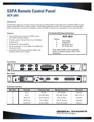
<strong>General</strong> <strong>Dynamics</strong>Series 1385 - 3.8M Rx/Tx Antenna SystemC4 Systems <strong>4096</strong>-<strong>757</strong>Quadrant 1Support FrameCFigure 15: Quadrant 1 AssemblyACInsertVariesItem 27TubeSupportFrameItems 22 – 24, 25, 261/2" HardwareReflector Quadrant Assembly12. Position quadrant 1 (quadrant 3 forinverted) to the top side of the frameas shown in Figure 15, Quadrant 1Assembly. Note that it may benecessary to loosen the three insertsthat pass through the reflector toattain the proper alignment with thethree tubes in the support frame.This procedure may occur with eachof the quadrants.13. After the quadrant is in position,place a Reflector Locator Spacer(item 27) between each insert andtube (see Figure 16, ReflectorSupport Reflector Detail). You willrepeat this procedure for all fourquadrants by referring to Figure 16.14. Secure the quadrant to the framewith the 1/2" hardware. See Figure16, Reflector Support ReflectorDetail. Note that there are threedifferent 1/2" bolt lengths:Location A = (items 23, 25, 26)Location B = (items 22, 25, 26)Location C = (items 24, 25, 26)These locations are consistent withall four quadrants. Tighten hardwareonly until snug.Figure 16: Reflector Support Reflector Detail15
<strong>General</strong> <strong>Dynamics</strong>Series 1385 - 3.8M Rx/Tx Antenna SystemC4 Systems <strong>4096</strong>-<strong>757</strong>BBQuadrant 215. Position quadrant 2 (quadrant 4 forinverted) to the right side of the frame asshown in Figure 17, Quadrant 2 Assembly.16. Place Locator Spacers as in step 12 andFigure 16, Reflector Support ReflectorDetail.A17. Secure the quadrant to the frame with 1/2"hardware. See Figure 16. Note that thereare three different 1/2" bolt lengths:Location A = (items 23, 25, 26)Location B = (items 22, 25, 26)Location C = (items 24, 25, 26)18. Secure Quad 1 and 2 together with 3/8"hardware (items 28 – 31). See Figure 20,Reflector Seam Hardware Detail, Page 17.19. Position quadrant 4 (quadrant 2 forinverted) to the left side of the frame asshown in Figure 18, Quadrant 4 Assembly.Figure 17: Quadrant 2 Assembly20. Place Locator Spacers as in step 12 andFigure 16, Reflector Support ReflectorDetail.AB21. Secure the quadrant to the frame with 1/2"hardware. See Figure 16. Note that thereare three different 1/2" bolt lengths:Location A = (items 23, 25, 26)Location B = (items 22, 25, 26)Location C = (items 24, 25, 26)Quadrant 422. Secure Quad 4 and 1 together with 3/8"hardware (items 28 – 31). See Figure 20,Reflector Seam Hardware Detail, Page 17.23. Position quadrant 3 (quadrant 1 forinverted) to the bottom of the frame asshown in Figure 19, Quadrant 3 Assembly.Figure 18: Quadrant 4 AssemblyC24. Place Locator Spacers as in step 12 andFigure 16, Reflector Support ReflectorDetail.A25. Secure the quadrant to the frame with 1/2"hardware. See Figure 16. Note that thereare three different 1/2" bolt lengths:Location A = (items 23, 25, 26)Location B = (items 22, 25, 26)Location C = (items 24, 25, 26)Quadrant 326. Secure Quad 3 and 2, and Quad 3 and 4together with 3/8" hardware (items 28 –31). See Figure 20, Reflector SeamHardware Detail, Page 17.Figure 19: Quadrant 3 Assembly16