4096-757 - General Dynamics SATCOM Technologies
4096-757 - General Dynamics SATCOM Technologies
4096-757 - General Dynamics SATCOM Technologies

You also want an ePaper? Increase the reach of your titles
YUMPU automatically turns print PDFs into web optimized ePapers that Google loves.
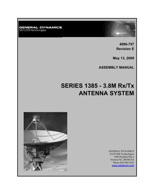
<strong>4096</strong>-<strong>757</strong>Revision EMay 13, 2009ASSEMBLY MANUALSERIES 1385 - 3.8M Rx/TxANTENNA SYSTEMGENERAL DYNAMICS<strong>SATCOM</strong> <strong>Technologies</strong>1500 Prodelin DriveNewton NC 28658USAPhone 828-464-4141www.gdsatcom.com
<strong>General</strong> <strong>Dynamics</strong>Series 1385 - 3.8M Rx/Tx Antenna SystemC4 Systems <strong>4096</strong>-<strong>757</strong>SERIES 1385 - 3.8M Rx/TxANTENNA SYSTEMLegal Notice<strong>General</strong> <strong>Dynamics</strong>’ drawings, sketches, computer programs, plans, specifications, technical data, prototype products,blueprints, photographs, instructions, diagrams, models, formulae, tables, engineering designs, diskettes, tapes, software,other electronic media (defined to include, but not be limited to, the system functional design, logic flow, algorithms,application programs, operating systems, software design implementation, tests, test results, operation, diagnosis,repair...) and/or documents (collectively "Proprietary Materials") are confidential and proprietary in nature and areconsidered by it to constitute "trade secrets" as defined by N.C. Gen. Stat. 66-152 (3)(a) and (b) of the North CarolinaUniform Trade Secrets Act, by the Uniform Trade Secrets Act and by any other states'/countries' Trade Secrets Actsregardless if some of the information or documents that were incorporated into such drawings, sketches, computerprograms, plans, specifications, technical data, prototype products, blueprints, photographs, instructions, diagrams,models, formulae, tables, engineering designs, diskettes, tapes, software, other electronic media (defined to include, butnot be limited to, the system functional design, logic flow, algorithms, application programs, operating systems, softwaredesign, implementation, tests, test results, operation, diagnosis repair...) and/or documents or other information that wasincorporated into the Proprietary Materials came from a customer or third party and whether such Proprietary Materials door do not constitute intellectual property, patent, trademark or copyright rights or material. THESE "PROPRIETARYMATERIALS" MAY NOT BE COPIED, REPRODUCED, DISCLOSED OR DISTRIBUTED IN WHOLE OR IN PART TO OTHERPARTIES EITHER VERBALLY OR IN WRITING WITHOUT PRIOR WRITTEN APPROVAL BEING OBTAINED FROM THEPRODELIN DOCUMENTATION SUPERVISOR OR A DULY AUTHORIZED REPRESENTATIVE.E Remove Page 27 28 10/21/09 RAHD Revised Table 1 5/13/09 RAHCBARevised pages #9 , (correctedhardware quantitiesand clarified purposeof vertex spacer.)Revised petalassembly sequencefor clarity, fig 7, 17, 18Released ForProduction.04/07/2009 R.F.12/11/08 KGD11/30/07 R.F.1 Original Release 09/13/2007 KGDRevision Description Date Approved Byii
<strong>General</strong> <strong>Dynamics</strong>Series 1385 - 3.8M Rx/Tx Antenna SystemC4 Systems <strong>4096</strong>-<strong>757</strong>Table of ContentsList of Illustrations …………………..…………………... ivList of Tables …………………..…………………... viPreface …………………..…………………... vii1. <strong>General</strong> Information …………………..…………………... 11.1. Warnings in this Manual …………………………................ 11.2. Unpacking and Inspection …………………………................ 21.3. Mechanical Installation Tools …………………………................ 21.4. Site Selection …………………………................ 32. Mast and Foundation …………………..…………………... 32.1. In-ground Mast …………………………................ 32.2. Pedestal Foundation …………………………................ 33. Reflector and Support Assembly …………………..…………………... 93.1. Parts List …………………………................ 93.2. Az/El Positioner Installation …………………………................ 103.3. Reflector Quadrant Orientation …………………………................ 103.4. Reflector Support Assembly …………………………................ 124. Feed and Support Assembly …………………..…………………... 184.1. Parts List …………………………................ 184.2. Feed Support Installation …………………………................ 194.3. Ku-Band Feed Assembly …………………………................ 225. Antenna Pointing …………………..…………………... 245.1. Alignment to the Satellite …………………………................ 245.2. Initial Alignment …………………………................ 246. Maintenance …………………..…………………... 266.1. Maintenance Overview …………………………................ 266.2. Periodic Inspection …………………………................ 266.3. Reflector …………………………................ 266.4. Mount and Reflector Support Structure …………………………................ 266.5. Feed and Feed Support …………………………................ 26iii
<strong>General</strong> <strong>Dynamics</strong>Series 1385 - 3.8M Rx/Tx Antenna SystemC4 Systems <strong>4096</strong>-<strong>757</strong>List of IllustrationsFigure 1: Typical In-Ground Mast Mount ……………..……………………...................... 4Figure 2: Typical Concrete Pad-Style Foundation ……………..……………………...................... 6Figure 3: Typical Concrete Pier-Style Foundation …………………………………...................... 7Figure 4: Az/El Positioner Assembly …………………………………...................... 10Figure 5: Standard Quadrant Orientation …………………………………...................... 11Figure 6: Inverted Quadrant Orientation …………………………………...................... 11Figure 7: Threaded Insert Location Layout (FrontView)…………………………………...................... 12Figure 8: Threaded Insert Assembly Detail …………………………………...................... 12Figure 9: Cross Arm Detail …………………..………………...................... 13Figure 10: Cross Arm Support Frame Assembly …………………..………………...................... 13Figure 11: Cross Arm Support Frame Labeling …………………..………………...................... 13Figure 12: Support Frame Positioner Assembly ………………….………………...................... 14Figure 13: Vertex Spacer Assembly …………………..………………...................... 14Figure 14: Vertex Spacer Detail …………………..………………...................... 14Figure 15: Quadrant 1 Assembly …………………..………………...................... 15Figure 16: Reflector Support Reflector Detail …………………..………………...................... 15Figure 17: Quadrant 2 Assembly …………………..………………...................... 16Figure 18: Quadrant 4 Assembly …………………..………………...................... 16Figure 19: Quadrant 3 Assembly ……………..……………………...................... 16Figure 20: Reflector Seam Hardware Detail ……………..……………………...................... 17Figure 21: Elevation Upper Connection Assembly ……………..……………………...................... 17Figure 22: Elevation Lower Connection Assembly ……………..……………………...................... 17Figure 23: Feed Rod Reflector Assembly ……………..……………………...................... 19Figure 24: Feed Rod Reflector Detail ……………..……………………...................... 19iv
<strong>General</strong> <strong>Dynamics</strong>Series 1385 - 3.8M Rx/Tx Antenna SystemC4 Systems <strong>4096</strong>-<strong>757</strong>List of Illustrations, cont'dFigure 25: Feed Support Feed Rod Assembly ……………..……………………...................... 20Figure 26: Feed Support Feed Rod Detail ……………..……………………...................... 20Figure 27: Feed Support Reflector Assembly ……………..……………………...................... 21Figure 28: Feed Support Reflector Detail ……………..……………………...................... 21Figure 29: Ku-Band Feed Assembly ……………..……………………...................... 23Figure 34: Antenna Alignment Hardware Overview ……………..……………………...................... 25v
<strong>General</strong> <strong>Dynamics</strong>Series 1385 - 3.8M Rx/Tx Antenna SystemC4 Systems <strong>4096</strong>-<strong>757</strong>List of TablesTable I: Hardware Size, Recommended Wrench and Torque Table ……………..………………….. 2Table II: Pedestal Mount Kit Part List ……………..………………….. 7Table III: Reflector and Support Assembly Part List ……………..………………….. 9Table IV: Feed Support Assembly Part List ……………..………………….. 18Table V: Ku-Band Feed Part List ……………..………………….. 22vi
<strong>General</strong> <strong>Dynamics</strong>Series 1385 - 3.8M Rx/Tx Antenna SystemC4 Systems <strong>4096</strong>-<strong>757</strong>PrefacePurposeThis manual provides instructions for the installation of the 3.8-meter Ku-Band Antenna system. It coverstopics that range from shipping inspection of the unassembled components to maintenance of the installedterminal.AudienceThis manual is a guide to an installer experienced in performing the various installation tasks. It shows thespecific tasks for installing the 3.8-meter Antenna System. The following general tasks may be required of theinstaller:• Use medium to large hand tools that require medium to heavy exertion of force.• Assist erection team personnel in the lifting and locating of heavy components.• Determine whether there are water pipes, electrical wiring, or gas lines hidden near wherethey are installing the antenna.• Route coaxial cable(s) through a foundation, walls, and/or floors.• Ground the antenna and coaxial cable as recommended in the National Electrical Code(published by the National Fire Protection Association, Batterymarch Park, Quincy, MA02269).The following are also possible users for this manual:• Call Center personnel• Call Center personnel trainersRelated DocumentationThe installer should reference all local building code regulations pertinent to the area in which they install theantenna. The installer should consult a local architect or civil engineer in determining the required foundation orother structural-related details for the specific site.vii
<strong>General</strong> <strong>Dynamics</strong>Series 1385 - 3.8M Rx/Tx Antenna SystemC4 Systems <strong>4096</strong>-<strong>757</strong>1. <strong>General</strong> Information1.1. Warnings in this ManualFor your safety and protection, read this entire manual before you attempt to install the antenna system. Inparticular, read this safety section carefully. Keep this safety information where you can refer to it ifnecessary.DANGERThis graphic indicates an imminently hazardous situation, which, if not avoided, will result in death orserious injury.WARNINGThis graphic indicates a potentially hazardous situation, which, if not avoided, could result in death orserious injury.CAUTIONThis graphic indicates potentially hazardous situation, which, if not avoided, may result in minor ormoderate injury.CAUTIONThis graphic indicates a situation or practice that might result in property damage.1
<strong>General</strong> <strong>Dynamics</strong>Series 1385 - 3.8M Rx/Tx Antenna SystemC4 Systems <strong>4096</strong>-<strong>757</strong>1.2. Unpacking and InspectionThe antenna containers should be unpacked and inspected at the earliest date to ensure that all material isincluded and is in good condition. Included with the material is a complete packing list for each majorcomponent.CAUTIONDo not drag the reflector support frame. The reflector attachment sleeves are factory set and youmust not alter as this may result in poor antenna performance.Regarding freight damage, you should direct any materials, damaged while in transit to the freight carrier.He will instruct you on the matters regarding any freight damage claims.Regarding material, missing or damaged, you should direct any questions regarding missing or damagedmaterials that is not due to freight carrier to Prodelin's Customer Service Department at:<strong>General</strong> <strong>Dynamics</strong> C4 Systems1500 Prodelin DriveNewton NC 28658USA(828) 464-41411.3. Mechanical Installation ToolsDuring the installation, you should have convenient access to general-purpose hand and power tools. Thefollowing specific tools are required; however, site dependent materials and processes may requireadditional tools:• Adjustable Crescent Wrench 10"• Ratchet (3 / 8" and 1 / 2" Drive)• 3" Wrench (socket, crescent or pipe) for 2" bolt• Allen Wrench, 5/32"• Screw Driver (standard and cross blade)• Inclinometer and Compass• Step Ladder2
<strong>General</strong> <strong>Dynamics</strong>Series 1385 - 3.8M Rx/Tx Antenna SystemC4 Systems <strong>4096</strong>-<strong>757</strong>Table I, below, describes the hardware that will require tools during the installation and pointing of theantenna. The table includes both metric and SAE sizes.Hardware Size SAE Wrench Size Metric Wrench Size Maximum Recommended Torque1 / 4" 7 / 16" 11 mm 80 in-lbs5 / 16" 1 / 2" 13 mm 140 in-lbs3 / 8" 9/16" 14 mm 20 ft-lbs1 / 2" 3 / 4" 20 mm 45 ft-lbs3 / 4" 1 – 1 / 8" 28 mm 145 ft-lbs7 / 8" 1 – 1 / 4" 32 mm N / A1" 1 – 1 / 2" 38 mm 220 ft-lbsTable I: Hardware Size, Recommended Wrench and Torque TableNOTE: The Minimum Torque applied should not be less than 10% of maximum recommended torque.1.4. Site SelectionIn order to achieve maximum performance of your antenna system, it is important to select the correctlocation for the antenna. You should observer the following guidelines when selecting a site for the installation:• The line of site to the satellite should be clear of any obstructions, such as trees or buildings.• The site should be relatively flat and level for ease of installation and access to the antenna.• Any underground obstructions, such as buried cables or pipes, need to be clearly marked beforeany excavation.• All local building codes should be adhered to (i.e. grounding, foundation requirements, zoningrules, setbacks, etc.).3
<strong>General</strong> <strong>Dynamics</strong>Series 1385 - 3.8M Rx/Tx Antenna SystemC4 Systems <strong>4096</strong>-<strong>757</strong>2. Suggested Mast and FoundationsWARNINGDue to the wide variety of soil conditions, Prodelin Corporation does not warrant that any particulardesign or size of foundation is appropriate for any locality or earth station installation. It is theresponsibility of the installer/user to determine if it meets the site/locality requirements. If there is anydoubt, have it checked by an architect or structural engineer.2.1. In-Ground Mast MountFigure 1, Typical In-Ground Mast Mount, shows is a mechanical specification for a suggested In-GroundMast. The pipe is 10 in. schedule 40, and is 15 ft. in length. Due to the high cost of shipping, Prodelinrecommends that the installer purchase this pipe from a local reseller. Note that the Az/El PositionerInterface is a Slip Flange, which is included with the antenna. The installation requires a qualified welder toweld the Slip Flange to the pipe on-site to the specification shown in Figure 1. Immediately followingFigure 1 is a list of other considerations related to installation of the In-Ground Mast Mount.10 in. SCH-40 PIPE(10.75 in. O.D.)5.502 - 52 PLCSSLIP FLANGE(0156-898).460.030.0SECTION A-AAA120.0SEE NOTES onpage 52" x 2 - 1/4" HRS ANGLE24" LONGTYPICAL TWO PLACES36.0ESTIMATE 2 YARDS CONCRETEFigure 1: Typical In-Ground Mast Mount4
<strong>General</strong> <strong>Dynamics</strong>Series 1385 - 3.8M Rx/Tx Antenna SystemC4 Systems <strong>4096</strong>-<strong>757</strong>The following is a list of additional considerations related to the In-Ground Mast Mount:• The 2" x 2" x ¼" HRS Angles and the 10" Sch-40 pipe are required to conform to ASTM A36structural steel requirements.• All concrete are required to conform to building code standards and have a minimum compressivestrength of 3000psi at 28 days. (Per ACI-318-77)• Soil bearing capacity is required to be no less than 2000psf.• Pour concrete against undisturbed soil.• Allow concrete 24 hrs to set before installation of the antenna.• Ground the antenna to meet applicable local codes.• Foundation depth is required to be minimum depth as shown or extended to local frost line.2.2. Pedestal MountThe Prodelin Pedestal Mount used with either a concrete pad-style or pier-style foundation. Figure 2,Typical Concrete Pad-Style Foundation, shows a suggested Pad Foundation. Figure 3, Typical ConcretePier-Style Foundation, shows a suggested Pier Foundation. Table II, Pedestal Mount Kit Parts List, lists thecomponents provided with the Pedestal Mount kit. Depending on the site requirements, you may choosebetween the Pad Foundation and the Pier Foundation. Both foundation designs accommodate Prodelin'sPedestal Mount. To install the Pedestal Mount foundation, reference Table II and Figure 2 or Figure 3,depending upon which foundation is used, and follow the steps below:1. Install one 1"-8 hex nut and one 1" flat washer (items 2,3) onto the anchor rod (item 5), then insertthe anchor rod into one of the holes in the plywood template (item 6) and install another 1"-8 hexnut and 1" flat washer. Repeat this procedure for the remaining anchor rods. This will keep all theanchor rods in the straight and proper orientation when pouring the concrete. Next, install two 1"-8hex nuts and one 1" flat washer (items 2, 3) on the other end of each anchor rod.2. Once the site location is determined, dig up the area in which you will install the foundation. Digonly to the depth required so that the soil in the bottom and sides of the foundation hole willremain undisturbed. Position the reinforcing bars as shown. Position the anchor rods so that theflat washers are under the reinforcing bars. Pour the concrete and allow it to set for 24 hours.3. Once the concrete is dry, remove the plywood template and screw the lower hex nuts as far downon the anchor rods as possible. Then install the mast pipe (item 1) on to the anchor rods. Adjustthe lower hex nuts until the mast pipe is level in the vertical position. Reinstall the flat washers,lock washers and hex nuts. With the mast pipe tightened down, fill the space between the concreteslab and the mast pipe base with grout.5
<strong>General</strong> <strong>Dynamics</strong>Series 1385 - 3.8M Rx/Tx Antenna SystemC4 Systems <strong>4096</strong>-<strong>757</strong>Tie all rebarintersections withwire.7.0"Item 6 TemplateRemove beforeinstalling PedestalMount.96.0"82.0"Items 2 – 5Hardware andRodsItem 7 #6 Reinforcement Bars.Space these equally in bothdirections.7.0"82.0"96.0"1-1/2" Grout Leveling(If required)Item 1Item 54.0"Item 2 – 4Items 2 – 330.0"27.0"3.0" MIN (TYP)Items 2 – 3Figure 2: Typical Concrete Pad-Style Foundation6
<strong>General</strong> <strong>Dynamics</strong>Series 1385 - 3.8M Rx/Tx Antenna SystemC4 Systems <strong>4096</strong>-<strong>757</strong>Item 5Items 2 – 41-1/2" Grout Leveling(If required)Items 2 – 34.0"Item 7 #6 Reinforcement BarsSpace these equally in bothdirections27.0"#3 Ties @ 14" center tocenterItems 2 – 3120.0"3000 psi Concrete30" DIAFigure 3: Typical Concrete Pier-Style Foundation7
<strong>General</strong> <strong>Dynamics</strong>Series 1385 - 3.8M Rx/Tx Antenna SystemC4 Systems <strong>4096</strong>-<strong>757</strong>Pedestal Mount Kit Part ListITEM NO. PART NO. DESCRIPTION QTY1 0490-2853.8M PEDESTAL MASTPIPE12 8107-007 1"-8 HEX NUT 3238201-0498201-0461" FLATWASHER USS1” FLATWASHER SAE8164 8202-046 1" LOCKWASHER 85 0180-238 1 - 8 X 36" ANCHOR ROD 86 0274-013 TEMPLATE, PLYWOOD 1Table II: Pedestal Mount Kit Part List8
<strong>General</strong> <strong>Dynamics</strong>Series 1385 - 3.8M Rx/Tx Antenna SystemC4 Systems <strong>4096</strong>-<strong>757</strong>3. Reflector and Support Assembly3.1. Parts ListTable III, Reflector and Support Assembly Parts List, provides a list of parts, descriptions and partnumbers. This table will serve a reference throughout the assembly process. The item number shown in thistable identifies parts and assemblies by reference in the following illustrations and text. Mark this page insome manner so you can look back at it easily.Reflector and Support Assembly Part ListITEM NO. PART NO. DESCRIPTION QTY1 0159-273 THREADED INSERT - # 1 42 0159-272 THREADED INSERT - # 2 23 THIS LINE INTENTIONALLY LEFT BLANK4 0159-271 THREADED INSERT - # 4 25 0159-275 THREADED INSERT - # 5 26 0159-274 THREADED INSERT - # 6 27 Varies REFLECTOR, QUADRANT # 1 18 Varies REFLECTOR, QUADRANT # 2 19 Varies REFLECTOR, QUADRANT # 3 110 Varies REFLECTOR, QUADRANT # 4 111 0181-262 Az/El POSITIONER ASSEMBLY 112 0181-485 CROSSARM ASSEMBLY 213 0181-486 SUPPORT FRAME ASSEMBLY 114 0181-187 ELEVATION ROD ASSEMBLY 115 8035-024 BOLT, 3/4 -10 x 3.00 1216 8201-047 FLATWASHER, 3/4" 2417 8202-045 LOCKWASHER, 3/4" 1218 8106-006 NUT, HEX 3/4" 1219 8201-052 FLATWASHER, 7/8" 1220 8202-052 LOCKWASHER, 7/8" INTERNAL TOOTH 1221 8110-007 JAM NUT, HEX 7/8"-9 1222 8033-064 BOLT, 1/2 – 13 x 8.00 423 8033-061 BOLT, 1/2 – 13 x 9.00 524 8033-096 BOLT, 1/2 – 13 x 12.00 425 8201-033 FLATWASHER, 1/2" 1326 8202-043 LOCKWASHER, 1/2" 1327 0168-260 SPACER, 3.8M REFLECTOR LOCATOR 1228 8032-014 BOLT, 3/8 – 16 x 1.75 3229 8201-042 FLATWASHER, 3/8" 6430 8202-042 LOCKWASHER, 3/8" 3231 8102-007 NUT, HEX 3/8" 3232 8036-016 BOLT, 1 – 8 x 2.00 433 8036-036 BOLT, 1 – 8 x 4.50 234 8036-040 BOLT, 1 – 8 x 5.00 235 8201-049 FLATWASHER, 1" 1036 8202-046 LOCKWASHER, 1" 837 8107-007 1”-8 HEX NUT 238 0159-404 SPACER, 3.8M VERTEX 1Table III: Reflector and Support Assembly Parts List9
<strong>General</strong> <strong>Dynamics</strong>Series 1385 - 3.8M Rx/Tx Antenna SystemC4 Systems <strong>4096</strong>-<strong>757</strong>CAUTIONDuring the assembly procedure, follow the sequence of instructions as stated.Do not tighten any hardware until instructed.3.2. Az/El Positioner InstallationFigure 4, Az/El Positioner Assembly, and the following text describe the steps required to install the Az/Elpositioner assembly:Towards DesiredAzimuth HeadingItems 15 – 16Items 16 – 18Item 111. Lift the Az/El positioner assembly (Item11) on top of the pedestal mast so that itrests upon the slip flange.2. Rotate the positioner assembly towardsthe desired azimuth heading as shown.3. Once the position is located, rotate thepositioner in either direction to the nearestset of holes. The result is a coarse azimuthsetting (+/- 30 deg.). The fine azimuthsetting will be set later.4. Secure the positioner to the pedestal with3/4" hardware (items 15 – 18). Tightensecurely.Figure 4: Az/El Positioner Assembly3.3. Reflector Quadrant OrientationYou can assemble the 3.8M reflector quadrants in either the standard or the inverted positions. Thereflector quadrants are labeled 1, 2, 3 and 4. You can find these numbers on the back of each quadrantembossed into the fiberglass. In the standard upright position, the antenna elevation-angle range is between12 and 90 degrees. When viewed from behind in the standard position (feed support at the bottom),quadrant #1 should be at the top; #2 on the left; #3 at the bottom and #4 on the right. See Figure 5, StandardQuadrant Orientation.However, to allow a lower profile installation or in areas of high snow accumulation, the reflector can beassembled in the inverted position (feed support at the top). In this position, quadrant #1 would be at thebottom; #2 on the right; #3 at the top and #4 on the left. See Figure 6, Inverted Quadrant Orientation.CAUTIONWe do not recommend inverting systems with the Anti-Ice feature. The inverted assembly would prohibitproper heating element location.10
<strong>General</strong> <strong>Dynamics</strong>Series 1385 - 3.8M Rx/Tx Antenna SystemC4 Systems <strong>4096</strong>-<strong>757</strong>1Feed Rod HolesFeed Support HolesAt Bottom243Figure 5: Standard Quadrant Orientation3Feed Support HolesAt TopFeed Rod Holes4 21Figure 6: Inverted Quadrant Orientation11
<strong>General</strong> <strong>Dynamics</strong>Series 1385 - 3.8M Rx/Tx Antenna SystemC4 Systems <strong>4096</strong>-<strong>757</strong>3.4. Reflector Support AssemblyThe reflector support is the metal frame that supports the reflector, attaches the reflector to the Az/ElPositioner, and thus allows adjustment of the antenna elevation angle. The following figures and textdescribe the steps necessary to assemble the reflector support.CAUTIONThe reflector support frame includes a precision alignment feature. Do not drop or drag the frame duringthe installation process. Do not attempt to adjust the round tube spacers in the frame assembly, as theseare factory pre-set. If these spacers are loose or damaged, or there is any obvious damage to the frame,then you must obtain replacement parts for a successful installation.Q 464Q 3512211Q 1Q 2Figure 7: Threaded Insert Location Layout (Front View)15264Item 21Item 20Item 19Reflector Support Assembly1. Before beginning the reflector supportassembly, as shown in Figure 8,Threaded Insert Assembly Detail,install the 12 threaded inserts (items 1– 6) thru the face of each reflectorquadrant.2. Secure inserts with 7/8" hardware(items 19, 20, 21). Snug but do nottighten the hardware.Note that there are five different insertlengths, and the assembly requires fourof number 1 and two each of numbers 2,4, 5, & 6. Each insert must be in thecorrect position in each quadrant forcorrect assembly. The top of each insertis stamped with an insert number. Thenumbers shown in Figure 7, ThreadedInsert Location Layout, correspond withthe stamped numbers on the inserts.Quadrant FaceThreaded InsertFigure 8: Threaded Insert Assembly Detail12
<strong>General</strong> <strong>Dynamics</strong>Series 1385 - 3.8M Rx/Tx Antenna SystemC4 Systems <strong>4096</strong>-<strong>757</strong>½" HardwareCross armAnti-crush tube½" BoltFigure 9: Cross Arm DetailCross arms4. Locate the cross arms (item 12) andremove the 1/2" hardware and anticrushtubes. See Figure 9, CrossArm Detail.5. Lay the support frame (item 13) ona safe flat surface, being careful notto damage the tube spacers.6. Insert the anti-crush tubes into thefour holes on the back of the frameas shown in Figure 10, Cross ArmSupport Frame Assembly.7. Place each cross arm over the anticrushtubes and secure with the 1/2"hardware removed in step 2. Makesure label A of the support frame islocated with label A on the crossarm.8. Repeat procedure with labels B, Cand D. See Figure 11, Cross ArmSupport Frame Labeling. Verify thatall connections are tight and secure.Note: Insert hardware from crossarm side.Anti-Crush tubes(both sides)Support FrameFigure 10: Cross Arm Support Frame AssemblyCross armLabelsSupport FrameFigure 11: Cross Arm Support Frame Labeling13
<strong>General</strong> <strong>Dynamics</strong>Series 1385 - 3.8M Rx/Tx Antenna SystemC4 Systems <strong>4096</strong>-<strong>757</strong>Figure 12: Support Frame Positioner AssemblyVertex spacerSupport FrameItems 34 – 36Both SidesPositioner9. As shown in Figure 12, SupportFrame Positioner Assembly, lift theassembled support frame to theAz/El positioner and secure with 1"hardware (items 34, 35, 36). Lay theframe back to rest on positioner.10. Allow the support frame to rotateback until at rest against thepositioner.11. Install the vertex spacer, Item 38, asshown in Figure 13, Vertex SpacerAssembly. This vertex spacer is tocatch the lip in the nose of thereflector petals to help hold theweight of the petals duringassembly. Assemble the vertexspacer using Items 23, 25, and 26.See Figure 14, Vertex Spacer Detail.CAUTIONFigure 13: Vertex Spacer AssemblyDo not leave the reflector quadswithout the three bolts started in thestand-offs. The vertex spacer onlyserves to help bear the weight of thepetals until you have installed thehardware.Note: By design, there will be asmall positive gap between thereflector petals and the vertexspacer once all petals are in placeand the hardware has beentightened.Center SpacerTubeReflectorsurfaceFigure 14: Vertex Spacer Detail14
<strong>General</strong> <strong>Dynamics</strong>Series 1385 - 3.8M Rx/Tx Antenna SystemC4 Systems <strong>4096</strong>-<strong>757</strong>Quadrant 1Support FrameCFigure 15: Quadrant 1 AssemblyACInsertVariesItem 27TubeSupportFrameItems 22 – 24, 25, 261/2" HardwareReflector Quadrant Assembly12. Position quadrant 1 (quadrant 3 forinverted) to the top side of the frameas shown in Figure 15, Quadrant 1Assembly. Note that it may benecessary to loosen the three insertsthat pass through the reflector toattain the proper alignment with thethree tubes in the support frame.This procedure may occur with eachof the quadrants.13. After the quadrant is in position,place a Reflector Locator Spacer(item 27) between each insert andtube (see Figure 16, ReflectorSupport Reflector Detail). You willrepeat this procedure for all fourquadrants by referring to Figure 16.14. Secure the quadrant to the framewith the 1/2" hardware. See Figure16, Reflector Support ReflectorDetail. Note that there are threedifferent 1/2" bolt lengths:Location A = (items 23, 25, 26)Location B = (items 22, 25, 26)Location C = (items 24, 25, 26)These locations are consistent withall four quadrants. Tighten hardwareonly until snug.Figure 16: Reflector Support Reflector Detail15
<strong>General</strong> <strong>Dynamics</strong>Series 1385 - 3.8M Rx/Tx Antenna SystemC4 Systems <strong>4096</strong>-<strong>757</strong>BBQuadrant 215. Position quadrant 2 (quadrant 4 forinverted) to the right side of the frame asshown in Figure 17, Quadrant 2 Assembly.16. Place Locator Spacers as in step 12 andFigure 16, Reflector Support ReflectorDetail.A17. Secure the quadrant to the frame with 1/2"hardware. See Figure 16. Note that thereare three different 1/2" bolt lengths:Location A = (items 23, 25, 26)Location B = (items 22, 25, 26)Location C = (items 24, 25, 26)18. Secure Quad 1 and 2 together with 3/8"hardware (items 28 – 31). See Figure 20,Reflector Seam Hardware Detail, Page 17.19. Position quadrant 4 (quadrant 2 forinverted) to the left side of the frame asshown in Figure 18, Quadrant 4 Assembly.Figure 17: Quadrant 2 Assembly20. Place Locator Spacers as in step 12 andFigure 16, Reflector Support ReflectorDetail.AB21. Secure the quadrant to the frame with 1/2"hardware. See Figure 16. Note that thereare three different 1/2" bolt lengths:Location A = (items 23, 25, 26)Location B = (items 22, 25, 26)Location C = (items 24, 25, 26)Quadrant 422. Secure Quad 4 and 1 together with 3/8"hardware (items 28 – 31). See Figure 20,Reflector Seam Hardware Detail, Page 17.23. Position quadrant 3 (quadrant 1 forinverted) to the bottom of the frame asshown in Figure 19, Quadrant 3 Assembly.Figure 18: Quadrant 4 AssemblyC24. Place Locator Spacers as in step 12 andFigure 16, Reflector Support ReflectorDetail.A25. Secure the quadrant to the frame with 1/2"hardware. See Figure 16. Note that thereare three different 1/2" bolt lengths:Location A = (items 23, 25, 26)Location B = (items 22, 25, 26)Location C = (items 24, 25, 26)Quadrant 326. Secure Quad 3 and 2, and Quad 3 and 4together with 3/8" hardware (items 28 –31). See Figure 20, Reflector SeamHardware Detail, Page 17.Figure 19: Quadrant 3 Assembly16
<strong>General</strong> <strong>Dynamics</strong>Series 1385 - 3.8M Rx/Tx Antenna SystemC4 Systems <strong>4096</strong>-<strong>757</strong>Items 28 – 29Figure 20: Reflector Seam Hardware DetailChannelItems 29 – 31Items 35 – 37Items 34 – 35SupportFrame27. At this time, tighten all the 1/2", 3/8"and insert hardware alternating fromone side of a quadrant to another in acircular pattern starting at the centerand working outward. Check the faceof the reflector while tightening toensure all mating edges are flush.Elevation Rod Assembly28. Locate the elevation rod (item 14) andsecure between the channels on thesupport frame in the lower connectionholes with 1" hardware (items 34, 35,36, and 37). See Figure 21, ElevationUpper Connection Assembly.29. Refer to Figure 22, Elevation LowerConnection Assembly. Loosen the nutson the elevation rod so that the blockhas some freedom to move.30. Lift the support frame and position theblock between the tabs on thepositioner.31. Secure Block with 1" hardware (items32, 35, and 36). Tighten the 2" nutsagainst the block. Fine elevationadjustment will be set later.Item 14Figure 21: Elevation Upper Connection AssemblyElevation RodItems 32, 35, 36Block and NutsTabsFigure 22: Elevation Lower Connection Assembly17
<strong>General</strong> <strong>Dynamics</strong>Series 1385 - 3.8M Rx/Tx Antenna SystemC4 Systems <strong>4096</strong>-<strong>757</strong>4. Feed Support Assembly4.1. Parts ListTable IV, Feed Support Assembly Parts List, provides a list of parts, descriptions and part numbers. Thistable will serve a reference throughout the assembly process. The item number shown in this tableidentifies parts and assemblies by reference in the following illustrations and text. Mark this page in somemanner so you can look back at it easily.Feed Support Assembly Part ListITEM NO. PART NO. DESCRIPTION QTY1 0176-257 FEED ROD 22 Varies FEED SUPPORT TUBE 13 8033-026 BOLT, 1/2-13 x 3.25" 14 8032-012 BOLT, 3/8-16 x 1.50" 45 8201-043 FLATWASHER, 1/2" 26 8202-043 LOCKWASHER, 1/2" STD 17 8104-007 NUT, HEX, 1/2-13 18 8201-042 FLATWASHER, 3/8” 89 8202-042 LOCKWASHER 3/8” 810 8102-007 NUT HEX 3/8-16 8Table IV: Feed Support Assembly Part List18
<strong>General</strong> <strong>Dynamics</strong>Series 1385 - 3.8M Rx/Tx Antenna SystemC4 Systems <strong>4096</strong>-<strong>757</strong>CAUTIONDuring the assembly procedure, follow the sequence of instructions as stated.Do not tighten any hardware until instructed.4.2. Feed Support InstallationThe following text and figures describe the steps required to install the Feed Support. These are generalinstructions for a typical feed support. If your system is supplied with specific instructions for a particularfeed support, refer to those instructions at this time.1. Attach the long end of each feed rod(item 1) loosely to the sides of thereflector with 3/8" hardware (items 4, 8– 10). See Figure 23, Feed RodReflector Assembly. See Figure 24,Feed Rod Reflector Detail.Item 1Figure 23: Feed Rod Reflector AssemblyItems 8 – 10Items 4 and 8ReflectorItem 1Figure 24: Feed Rod Reflector Detail19
<strong>General</strong> <strong>Dynamics</strong>Series 1385 - 3.8M Rx/Tx Antenna SystemC4 Systems <strong>4096</strong>-<strong>757</strong>2. Position the feed support (item 2) infront of the reflector as shown andattach to the top ends of the feed rodswith 1/2" hardware (items 3, 5, 6, 7).See Figure 25, Feed Support Feed RodAssembly. See Figure 26, Feed SupportFeed Rod DetailItem 1Item 2Figure 25: Feed Support Feed Rod AssemblyItem 1Item 3Items 5 – 7Item 2Figure 26: Feed Support Feed Rod Detail20
<strong>General</strong> <strong>Dynamics</strong>Series 1385 - 3.8M Rx/Tx Antenna SystemC4 Systems <strong>4096</strong>-<strong>757</strong>3. Mount the other end of the feed supportalong to the bottom of the reflector with3/8" hardware (items 4, 8, 9, 10). SeeFigure 27, Feed Support ReflectorAssembly. See Figure 28, Feed SupportReflector Detail.Note: If you have purchased the FeedSupport Stabilizer, Kit P/N 0800-686,install it during step 3 above.Instructions for the installation of thestabilizer kit are included in thestabilizer kit packaging.4. Tighten all feed support hardware at thistime.Item 2Figure 27: Feed Support Reflector AssemblyItems 8 – 10ReflectorItem 2Items 4 and 8Figure 28: Feed Support Reflector Detail21
<strong>General</strong> <strong>Dynamics</strong>Series 1385 - 3.8M Rx/Tx Antenna SystemC4 Systems <strong>4096</strong>-<strong>757</strong>4.3. Ku-Band Feed AssemblyFor C-Band feed installation. (See Manual <strong>4096</strong>-772)The following text and figures describe the steps required to install a Ku-Band Feed. If your system isprovided with something other than a ku-band feed refer to the specific installation instructions suppliedwith that feed assembly at this time.<strong>General</strong> Dynamic’s 3.8-meter Ku-Band Rx/Tx Antenna System is available with a variety of Ku-Band feedassemblies. <strong>General</strong> <strong>Dynamics</strong> provides only the feed horn and hardware kit with the base antenna. If youhave purchased the feed assembly from <strong>General</strong> <strong>Dynamics</strong>, the feed support packaging contains additionalinstructions specific to the feed assembly.4.3.1. Parts ListTable V, Ku-Band Feed Part List, provides a list of parts, descriptions and part numbers. Thistable will serve a reference throughout the assembly process. The item number shown in this tableidentifies parts and assemblies by reference in the following illustrations and text. Mark this pagein some manner so you can look back at it easily.Ku-Band Feed Part ListITEM NO. PART NO. DESCRIPTION QTY1 0183-265 FEED HORN ASSEMBLY 12 0198-120 O-RING 13 8300-002 #6-32 x .50” SCREW 64 8200-010 #6 INTERNAL TOOTH LOCK WASHER 6Table V: Ku-Band Feed Part List22
<strong>General</strong> <strong>Dynamics</strong>Series 1385 - 3.8M Rx/Tx Antenna SystemC4 Systems <strong>4096</strong>-<strong>757</strong>4.3.2. Feed Assembly (Ku-Band)The following text and figures describe the steps required to install Ku-Band Linear Feeds:Figure 29: Ku-Band Feed AssemblyItem 3Item 4ODU(separate)Item 1Item 21. Attach the feed horn (item #1) to theODU using the six #6-32 x .50” screws,lock washers, and o-ring provided, items2 - 4. Apply silicone grease to o-ringbefore assembly. See Figure 29, Ku-Band Feed Assembly. Tighten securely.2. Refer to any additional instructions thatmay be included with the feed supportsystem for the particular antenna systemor refer to the instructions supplied bythe system integrator or electronicsmanufacturer to complete the feedinstallation.23
<strong>General</strong> <strong>Dynamics</strong>Series 1385 - 3.8M Rx/Tx Antenna SystemC4 Systems <strong>4096</strong>-<strong>757</strong>5. Antenna Pointing5.1. Alignment to the Satellite<strong>General</strong> <strong>Dynamics</strong> recommends that a trained or experienced installer align the 3.8-meter Az/El to thesatellite orbital arc. We intend these instructions in section 5.1 to be an overview of the alignmentprocedure.5.2. Initial AlignmentThe 3.8 meter offset reflector has a 22.62-degree elevation offset look angle. Therefore, when the reflectoraperture is perpendicular to the ground, the antenna look-angle is 22.62 degrees in elevation.The following steps summarize how to align the antenna initially:1. Raise the antenna by turning the 2" nuts on the elevation rod assembly.2. After the correct elevation angle is set, rotate the antenna in the azimuth plane by loosening the 2" nuton top of the positioner and removing the 1" hardware (4 places) in the positioner plate, refer to Figure34, Antenna Alignment Hardware Overview.3. At this time, rotate the antenna in azimuth by turning the 1" nuts located at the azimuth adjustmenttube. Rotate the antenna in the azimuth plane until you acquire a signal.4. Peak the antenna by fine adjustments made in both the elevation and the azimuth.5. Adjust polarization by rotating the feed assembly in its mounting bracket.6. Re-install the 1" hardware in the Az/El positioner from step 2 and tighten all adjustment hardwaresecurely.24
<strong>General</strong> <strong>Dynamics</strong>Series 1385 - 3.8M Rx/Tx Antenna SystemC4 Systems <strong>4096</strong>-<strong>757</strong>InclinometerUpright:(Adding 22.620 degrees toindicator reading gives you theelevation look angle)Inverted(Subtracting 22.620 degrees fromindicator reading gives you theelevation look angle)AzimuthAdjustmentElevationAdjustmentRemove 1" Hardware forAzimuth AdjustmentFigure 34: Antenna Alignment Hardware Overview25
<strong>General</strong> <strong>Dynamics</strong>Series 1385 - 3.8M Rx/Tx Antenna SystemC4 Systems <strong>4096</strong>-<strong>757</strong>6. Maintenance6.1. Maintenance OverviewAfter installation, the antenna requires only periodic inspection. You should anticipate that maintenance, ifrequired, would be minimal and easily handled by a local or in house maintenance staff. The materials usedin the construction of this Earth Station Antenna virtually eliminate any maintenance repairs.6.2. Periodic InspectionWe suggest that you perform a periodic inspection at least every six months. Note that after any very severeweather condition, you should inspect the antenna to determine if foreign objects have caused damage or ifconditions have exceeded survival specifications. During a periodic inspection, inspect the following items:6.3. Reflector• Check all bolted locations – all bolts should be tight.• Check all structural members – repair or replace if damaged.• Check the foundation anchor bolts – they should be secure and have no signs of potential failure.• Check for corrosion – observe the reflector and metal structure.Prodelin's reflector does not require any maintenance. The composite construction of the reflector isvirtually impervious to damage caused by weather or other atmospheric conditions.It is only necessary to inspect for any physical damage done by vandalism or very severe weatherconditions.Should you detect any damage be detected to a portion of the reflector, contact the Customer ServiceDepartment at Prodelin regarding reflector repair or replacement.6.4. Mount and Reflector Support StructureThe mount and reflector support structure supplied with this antenna is of steel construction and has agalvanized finish. The hardware has a zinc finish and a topcoat for corrosion protection.If inspection shows any sign of structural failure, repair or replace the damaged mount members.Repair any corrosion on steel members with a cold, zinc-rich, galvanizing paint.6.5. Feed and Feed SupportMake sure the feed support tube and feed rod hardware is secure, and the feed and radio mounting bolts aretight.Make sure the feed horn window is intact to prevent moisture from collecting inside the feed horn. Replaceif damaged.26