Coats CHD-9551 HD Tire Changer - NY Tech Supply
Coats CHD-9551 HD Tire Changer - NY Tech Supply
Coats CHD-9551 HD Tire Changer - NY Tech Supply
- No tags were found...

You also want an ePaper? Increase the reach of your titles
YUMPU automatically turns print PDFs into web optimized ePapers that Google loves.
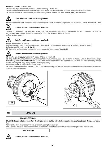
MOUNTING WITH THE HOOKED TOOL1) Follow the steps described in points 1,2,3,4,5 for mounting with the disk.2) Move the tool carrier arm to its non-working position. Move it to the inside face of the tire and rehook it at this position.3) Check to make sure the hook tool is positioned facing the tire bead. If not, press lever (9, Fig. C) and turn it 180°.Take the mobile control unit to work position D.4) Move the tool forward until the red reference dot is lined up with the outside edge of the rim and about 1/4 inch (5 mm) from it (SeeFig. O).Take the mobile control unit to work position C.5) Move to the outside of the tire assembly and check the exact position of the hook visually and adjust it as needed. Then turn thespindle clockwise until the clip is at the bottom (6 o’clock). The first bead will be on the rim.6) Remove the g-clamp.Take the mobile control unit to work position D.7) Remove the tool from the tire.8) Move the tool carrier arm to its non-working position. Move it to the outside plane of the tire and rehook it in this position.9) Turn the tool 180° with lever (9, Fig. C).10) Attach the g-clamp at the bottom (6 o’clock) outside the second bead (See Fig. N).Take the mobile control unit to work position C.11) Turn the spindle counterclockwise to about 90° (clip at 9 o’clock).12) Bring the tool forward until the red reference dot is lined up with the outside edge of the rim and about 1/4 inch (5 mm) from it. Beginto turn the spindle counterclockwise and check if, after about 90° of rotation the second bead has started to slip into the drop center.Continue turning until the g-clamp is at the bottom (6 o’clock).The second bead will now be mounted on the rim.13) Follow the steps described in points 11, 12, 13, 14, 15 for mounting with the disk, since this will ensure that the tire assembly is removedcorrectly from the machine.NO13.3 TUBE TIREBEAD LOOSENINGWARNING: Release inflation valve when deflating the tyre so that the valve, falling inside the rim, is not an obstacle during bead loosening.Follow all the steps described previously for bead loosening tubeless tyres.With tube tires, however, stop disk movement as soon as the bead has loosened to avoid damaging the tube inflation valve.DEMOUNTINGTake the mobile control unit to work position C.16