Coats CHD-9551 HD Tire Changer - NY Tech Supply
Coats CHD-9551 HD Tire Changer - NY Tech Supply
Coats CHD-9551 HD Tire Changer - NY Tech Supply
- No tags were found...

Create successful ePaper yourself
Turn your PDF publications into a flip-book with our unique Google optimized e-Paper software.
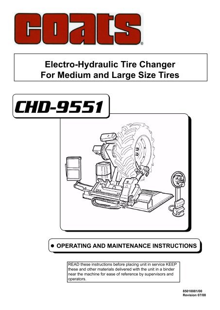
1GENERAL INFORMATIONThis tyre changer has been specifically designed to demount and mount truck, bus and commercial van tyres, with rims from 14" to 56"and a maximum 2.400 mm diameter.Any other use is improper and therefore not authorized. Before beginning any kind of work on or with this machine, carefully read andunderstand the contents of these operating instructions.The manufacturer shall not liable for any injury to persons or damage to things caused by improper use of this machine.KEEP THIS MANUAL NEAR THE MACHINE AND CONSULT IT AS NEEDED DURING OPERATIONS.2 TECHNICAL DATAElectric Power requirementPump motorGear-box motorHandles rim fromMax. wheel diameterMax. wheel widthMax. wheel weightWeight (with standard accessories)Acoustic pressure level (at work)220V - 3 PH - 60Hz 15 Amp1,1 kw1,8 / 1,85 kw14" - 56"2.400 mm1.300 mm1800 kg1025 KgLpA
B/1B/2lbs 2745(KG. 1245)A/26UNPACKINGOnce the packing material has been removed, check the machine visually for any signs of damage.Keep the packing materials out of the reach of children as they can be a source of danger.N.B.: Keep the packing for possible future transport.7 INSTALLATION7.1 INSTALLATION PLACEChoose the place the machine is to be installed in compliance with current work place safety regulations. The floor should not be brokenor uneven so that the machine will be stable and the platform rollers can move freely.If the installation is outdoor, it must be protected by some kind of roofing against rain.The following work environment conditions are applicable:Relative humidity: from 30-95% without condensation;Temperature: from 32°-131° F (0-55° C.)ATTENTION!The machine must not be operated in explosive atmospheres.7.2 WORKPLACE REQUIREMENTMaximum machine space requirements are 88.2x6.3 inches (2240x 1640 mm) with a minimum distance from walls as shown in the diagram.CAUTION! These measurements are also the tyre changers working range. Persons other than specially trained and authorized operatorsare expressly forbidden to enter this area.Position the tire changer lifting it with the specific bracket (1, Fig. A) with the tool carrier arm (2, Fig. A) lowered all the way, the spindle(3, Fig. A) closed and the tool carrier slide (4, Fig. A) at its stop close to the arm.The mobile control unit has no fixed position, but it must bepositioned in a way that the user can observe the machine when working
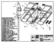
8LAYOUT OF FUNCTIONAL PARTS1 - Lifting bracket2 - Self-centering chuck holding arm3 - Self-centering chuck4 - Sliding ramp5 - Switch8 - Handler9 - Switch10 - Pedal11 - Handler13 - Carriage14 - Tool holding arm15 - Arm lever17 - Bead breaking disk18 - Tool19 - Arm locking cylinder22 - JawWARNING!During all operations, keep hands and other parts of the bodyas far as possible from moving parts of the machine. Necklaces,bracelets and too large clothes, can be dangerous for the operator.122324A589ceabd1714151811gh13 19f10CD
9 IDENTIFYING WARNING SIGNALSWARNING:Unreadable and missing warning labels must be replaced immediately. Do not use the tyre changerif one or more labels are missing. Do not add any object that could prevent the operator from seeingthe labels.Use ref. code #2019225 to order labels set, if needed.
DANGER!Do not very the work area with a wheel clamped on the tire changer and lifted up from the floor.13.2TUBELESS AND SUPERSINGLE TIRESBEAD LOOSENING1) Clamp the tire assembly on the self-centering chuck, as previously described, and ensure that the tire is deflated.2) Take the mobile control unit to work position C.3) Lower the tool-holder arm (14, fig. F) into working position and allow it to lock.DANGER!Always check to be certain that the arm is correctly hooked to the carriage.E/6E/7E/84) Operating from the mobile control centre, manoeuvre the wheel until the outside of the rim skims the bead-loosener disk (fig. F).DANGER!The bead loosener disk must NOT be pressed against the rim but against the tire bead.5) Rotate the wheel and at the same time, advance the loosener disk plate with small forward movements following the profile of therim.6) Continue until the first bead is fully detached.To facilitate this operation, lubricate the bead and the edge of the rim with tire lubricant whilst the tire assembly is rotated.CAUTION!To avoid all risk, lubricate the beads turning the tire assembly clockwise if you are working on the outsideface and counterclockwise if working on the inside face.12
Remember that the stronger the tire’s adherence to the rim, the slower must be the disk’s penetration.7) Move the tool carrier arm (14, Fig. F) back from the edge of the rim. Release the hook, raise the arm to its non-working position, shift itand rehook it in its second work position (Fig. G).DANGER!Do not hold your hands on the tool when you bring it back to its work position. Your hand(s) could be trappedbetween the tool and the tire assembly.8) Push the double headed tool lever (9, fig.C) and turn the head180° until it locks automatically. Then slide the tool-holder arm alongthe sliding table and lock it in position.9) Take the mobile control unit to work position D.Repeat the operation previously described until the second bead is completely loosened.During the bead loosening operation, the finger tool (18, fig.G) can be lowered so that it is out of the way.1418F GDEMOUNTINGTubeless tires can be demounted in two ways:1) If the tire is not difficult to demount, once the beads have been loosened, use the bead disk to push against the inside plane of thetire until both beads come off the rim (See Fig. H). Always keep the tire rotating while pushing with the bead disck2) With Supersingle or very hard tires the procedure described above cannot be used. The hook tool will have to be used as follows:- Transfer the tool carrier arm to the outside plane of the tire.Take the mobile control unit to work position C.- Rotate the tire assembly and at the same time move the hook tool forward inserting it between rim and bead until it is anchored tothe bead (See Fig. I).-Move the rim 1.5-2 inch (4-5 cm) from the tool taking care that it does not unhook from the bead.-Move the hook tool towards the outside until the red reference dot is by the outside edge of the rim.Take the mobile control unit to position B.- Insert lever (17, Fig. I) between rim and bead at the right of the tool.-Press down on the lever and lower the tire assembly to bring the edge of the rim about 2 inches (5 cm) from the hooked tool.-Turn the tire assembly counterclockwise pressing down on lever until the bead is completely off.-Move the tool carrier arm to its non-working position and then move it to the inside face of the tire assembly.Take the mobile control unit to work position D.13
-Place the tool carrier arm in the working position, then the bead disk to push against the inside face of the tire (see fig. H). It’s is best todo this with the wheel turning.17HTake the mobile control unit to work position B.I-Always keep the rotating counterclockwise, while pushing with the bead disk.Turn the wheel counterclockwise pushing with disk until the tire comes completely off the rim.DANGER!When the beads come off the rim, the tire will fall. Check to make sure there are no by-standers in the workarea.MOUNTINGTubeless tires can be mounted using either the bead loosener disk or the hook tool. If the tire is not problematic, use the bead loosenerdisk. If the tire is very rigid, the hook tool must be used.TIRE MOUNTING WITH THE DISKFollow these steps:1) If the rim has been removed from the spindle, put it back on the spindle as described in the section on “RIM CLAMPING”.2) Lubricate both beads and the rim with tyre manufacturer recommended lubricant.3) Attach the g-clamp to the outside edge of the rim at the highest point (See Fig. M).CAUTION!Make sure the g-clamp is firmly attached to the rim.Take the mobile control unit to work position B.4) Put the tire on the platform and lower the spindle (make sure the g-clamp is at the high point).5) Lift the rim with the tire hooked to it and turn it anticlockwise about 6-8 inches (15-20 cm). The tyre will be positioned included acrossthe rim.14
MLTake the mobile control unit to work position C.6) Position the bead loosener disk against the second bead of the tire and turn the spindle until the g-clamp is at the low point (at 6o’clock).7) Move the disk away from the tire assembly.8) Remove the g-clamp and riposition it at 6 o’clock outside the second bead (See Fig. N).9) Turn the spindle clockwise 90° to bring the g-clamp to 9 o’clock.10) Move the disk forward until it is about 0.5-1 inches (1-2 cm) inside the edge of the rim. Begin to turn the spindle clockwise checkingto make sure that, with a 90° turn, the second bead begins to slip into the drop center.11) When the bead is fully mounted, move the tool away from the tire assembly, tip it to its non-working position and remove the g-clamp.Take the mobile control unit to work position B.13) Close the arms of the spindle completely. Support the tire assembly to prevent it falling off.DANGER!Potentially hazardous operation!Do it manually only if you are certain you can keep the tire assembly balanced. For large and heavy tires14) Move the ramp to remove the tire asembly from the spindle.15) Remove the tire assembly.If the tire permits it, the operation described above can be speeded up by mounting both beads at the same time:- Follow the steps described under points 1,2,3,4 described above but instead of attaching the g-clamp to just the first bead (refer topoint 4) clip it to both.- Lift the rim with the tire hooked to it and turn it counterclockwise 6-8 inches (15-20 cm) (g-clamp at 10 o’clock).- Follow the steps described in points 10,11,12,13,14,15 above.N15
MOUNTING WITH THE HOOKED TOOL1) Follow the steps described in points 1,2,3,4,5 for mounting with the disk.2) Move the tool carrier arm to its non-working position. Move it to the inside face of the tire and rehook it at this position.3) Check to make sure the hook tool is positioned facing the tire bead. If not, press lever (9, Fig. C) and turn it 180°.Take the mobile control unit to work position D.4) Move the tool forward until the red reference dot is lined up with the outside edge of the rim and about 1/4 inch (5 mm) from it (SeeFig. O).Take the mobile control unit to work position C.5) Move to the outside of the tire assembly and check the exact position of the hook visually and adjust it as needed. Then turn thespindle clockwise until the clip is at the bottom (6 o’clock). The first bead will be on the rim.6) Remove the g-clamp.Take the mobile control unit to work position D.7) Remove the tool from the tire.8) Move the tool carrier arm to its non-working position. Move it to the outside plane of the tire and rehook it in this position.9) Turn the tool 180° with lever (9, Fig. C).10) Attach the g-clamp at the bottom (6 o’clock) outside the second bead (See Fig. N).Take the mobile control unit to work position C.11) Turn the spindle counterclockwise to about 90° (clip at 9 o’clock).12) Bring the tool forward until the red reference dot is lined up with the outside edge of the rim and about 1/4 inch (5 mm) from it. Beginto turn the spindle counterclockwise and check if, after about 90° of rotation the second bead has started to slip into the drop center.Continue turning until the g-clamp is at the bottom (6 o’clock).The second bead will now be mounted on the rim.13) Follow the steps described in points 11, 12, 13, 14, 15 for mounting with the disk, since this will ensure that the tire assembly is removedcorrectly from the machine.NO13.3 TUBE TIREBEAD LOOSENINGWARNING: Release inflation valve when deflating the tyre so that the valve, falling inside the rim, is not an obstacle during bead loosening.Follow all the steps described previously for bead loosening tubeless tyres.With tube tires, however, stop disk movement as soon as the bead has loosened to avoid damaging the tube inflation valve.DEMOUNTINGTake the mobile control unit to work position C.16
1) Tip the tool carrier arm (14, Fig. D) to its non-working position. Move it to the outside face of the tire and rehook it in this position.2) Rotate the tire assembly and at the same time move the hook tool (18, Fig. D) forward inserting it between rim and bead until it isanchored to the tool.3) Move the rim 1.5-2inch (4-5 cm) from the tool taking care that it does not unhook from the bead.4) Move the hook tool towards the outside until the red reference dot is by the outside face of the rim.Take the mobile control unit to work position B.5) Insert lever (see Fig. P) between rim and bead at the right of the tool.6) Press down on the lever and lower the tire assembly bring the edge of the rim about /4 inch (5 mm) from the hooked tool.7) Turn the tire counterclockwise pressing down on lever until the bead is completely off.8) Move the tool carrier arm to its non-working position. Lower the spindle until the tire is pressed down against the ramp . As the ramp ismoved slightly towards the outside, the tyre will open a little and thus create enough space to remove the inner tube.9) Remove the inner tube and lift the tire assembly back up.1714151813 19PDTake the mobile control unit to work position D.10) Move the tool carrier arm to the inside face of the tire, turn the hook tool 180° and lower the arm to its work position. Insert it betweenrim and bead and move it until the bead is by the front edge of the rim (best to do this with the tire assembly turning).11) Move the rim about 4-5 cm from the tool making sure the hook does not detach from the rim.Take the mobile control unit to work position B.12) Move the hook tool so that its red reference dot is about 1,2 inch (3 cm) inside the rim.13) Insert lever between rim and bead at the right of the tool (See Fig. Q).14) Press down on the lever and lower the tire to bring the edge of the rim about 2 inches (5 cm) from the hooked tool.Turn the tire assembly counterclockwise pressing down on lever until the tyre comes completely off the rim.DANGER!When the beads come off the rim, the tire will fall. Check to make sure there are no by-standers in thework area.MOUNTING1) If the rim has been removed from the spindle, put it back on the spindle as described in the section on “rim clamping”.2) Lubricate both beads and the rim with tire manufacturer recommended lubricant.3) Attach the g-clamp to the outside edge of the rim at the highest point (See Fig. R).CAUTION!Make sure the g-clamp is firmly attached to the rim.17
S16) Turn the spindle until the valve is at the bottom (6 o’clock).17) Inflate the inner tube a little (until it has no folds) so as not to pinch it while mounting the second bead.18) Attach an extension to the valve and then remove the locking ring.The purpose of this operation is to allow the valve to be loose so that it is not ripped out during second bead mounting.Take the mobile control unit to work position C.19) Lift the tire assembly again and attach the g-clamp outside the second bead about 8 inches (20 cm) to the right of the valve (SeeFig. U).20) Turn the spindle clockwise until the g-clamp is at 9 o’clock.21) Move the tool carrier arm (14, Fig. D) to its working position.22) Bring the tool forward until the red reference dot is lined up with the outside edge of the rim and about 1/4 inch (5 mm) from it.23) Turn the spindle a little clockwise until you can insert the bead guide lever into its seating on the hook tool (See Fig. V). This lever canbe supplied on demand.24) Pull back on this lever which will guide the bead into drop center. Continue to turn the spindle until the tire is completely mountedon the rim.25) Remove the g-clamp. Remove the hook tool by turning the spindle counterclockwise and moving it towards the outside.26) Tip the tool carrier arm to its non-working position.27) Position the ramp directly under the tire assembly and lower the spindle until the tire rests on the ramp.Take the mobile control unit to work position B.28) When the tire is resting on the ramp, check to make sure the valve is perfectly centered with its hole. If it is not, turn the spindle slightlyto adjust the position. Fix the valve with its locking ring and remove the extension.29) Close the arms of the spindle completely. Support the tire to prevent it falling off.TDANGER! POTENTIALLY HAZARDOUS OPERATION!Do it manually only if you are certain you can keep the tire assembly balanced. For large and heavy tires an adequatelifting device must be usedU V19
30) Move the ramp to release the tire from the spindle.31) Remove the tire.13.4 TIRES WITH SPLIT RINGBEAD LOOSENING AND DEMOUNTINGTIRE ASSEMBLIES WITH 3-PIECE RINGS1) Clamp the tire assembly on the spindle as described previously and check to make sure it has been deflated.2) Take the mobile control unit to work position B.3) Lower the tool carrier arm (14, Fig. D) to its work position until it is locked in position by its hook.4) Position the bead loosener disk level with the rim (See Fig. W).5) Turn the spindle and at the same time move the disk forward a bit at a time following the contour of the rim until the first bead is completelyfree (NB: lubricate while doing this).CAUTION! If the tire has an inner tube, work very carefully and be prepared to stop the disk immediately once the bead has been brokenso as not to damage the valve and the inner tube.6) Repeat this procedure but this time bring the disk against the split-ring (See Fig. Z) until the lock ring is freed. Remove this with the speciallever (19, Fig. Z) or with the help of the disk.7) Remove the split-ring.8) Move the tool carrier arm (14, Fig. D) back from the edge of the rim. Release the hook and tip the arm to its non-working position.Move the tool carrier arm to the inside face of the tire assembly.9) Press lever (9, Fig. C) and turn the tool head 180° which will automatically lock in this position. Lower the arm to its working position.10) Turn the spindle and at the same time bring the bead loosener disk up against the tire following the contour of the split-ring until thesecond bead has been broken (NB: Lubricate during this process).Continue to move the disk forward until about half the tire has demounted from the rim (See Fig. K).11) Move the tool carrier arm to its non-working position.12) Move the ramp (4, Fig. A) directly under the tire.13) Lower the spindle until the tire is resting on the ramp.19W ZTake the mobile control unit to work position B.14) Move the ramp towards the outside until the tire is completely off the rim. Watch out for the valve!TIRE ASSEMBLIES WITH 5-SEGMENT SPLIT RINGS1) Clamp the tire assembly on the spindle as described previously and make sure it is deflated.Take the mobile control unit to work position C.20
2) Lower the tool carrier arm (14, Fig. D) to its work position until its hook has engaged into position on the carriage.3) Use the joystick to position the wheel so that the bead loosener disk touches up against outside edge of the centre well rim.4) Turn the spindle and at the same time move the bead loosener disk forward until the split-ring is detached. Watch out for the O-ring.5) Repeat this operation but this time move the disk against the split-ring (See Fig. Z) until the locking ring is released. this ring can beremoved with the special lever (19, Fig. Z) or with the help of the bead disk.6) Remove the O-ring7) Move the tool carrier arm (14, Fig. D) back from the edge of the rim. Release the hook and tip the arm to its non-working position.Move the tool carrier arm to the inside face of the tire.8) Press lever (9, Fig. C) and turn the tool head 180° which will automatically lock in this position. Lower the arm to its working position.Take the mobile control unit to work position D.9) Turn the spindle and at the same time bring the bead loosener disk up against the tyre between the rim and bead. Move the diskinto the tyre only when the bead has started to detach from the rim, and move the bead to the outside edge of the rim. (NB: Lubricateduring this process).10) Tip the tool carrier arm to its non-work position.Take the mobile control unit to work position B.11) Move the ramp (4, Fig. A) directly under the tire.1714151813 19KD12) Lower the spindle until the tire is resting on the ramp.13) Move the ramp towards the outside until the tire together with the split ring comes completely off the rim.14) Remove the rim from the spindle.15) Position the tire on the platform with the splint ring turned towards the spindle.16) Clamp the split ring on the spindle as explained in the section of RIM CLAMPING.DANGER!The tire is not attached to the split ring completely. Any strain on it during positioning or clamping operations could causeit to detach and fall.Take the mobile control unit to work position D.17) Lift the tire assembly.18) Move the tool carrier arm back to its work position.19) Position the spindle so that the bead loosener disk is lined up with the bead.20) Turn the spindle and move the disk forward until the tire comes completely off the split ring.This double bead breaking procedure can be eliminated by using the pair of clamps #9299273 (optional) that fix the split-ring to therim so that they are loosened out at the same time.DANGER!When the beads come off the rim, the tire will fall. Check to make sure there are no by-standers inthe work area.21
MOUNTINGTIRE ASSEMBLY WITH 3-PIECE SPLIT-RINGS1) Move the tool carrier arm to its non-working position. If the rim has been removed from the spindle, put it back on the spindle as describedin the section on “RIM CLAMPING”.If the tire is tubed, position the rim with the valve slot at the bottom (6 o’clock).2) Lubricate both beads and the rim with tire manufacturer recommended lubricant.Take the mobile control unit to work position B.3) Move the platform to be able to place the tire on it.If the tire is tubed, position the rim with the valve slot at the bottom (6 o’clock).4) Lower or raise the spindle to centre the rim and the tire.5) Move the ramp forward until the rim is inserted into the tire.CAUTION! If the tire is tubed push the valve inside so as not to damage it.Move forward with the ramp until rim is completely in the tire.6) Bring the tool carrier arm to the outside face and lower it to its work position with the disk facing the tire.If the tire is not inserted sufficiently on the rim, move the spindle until the tire bead is by the disk. Bring the disk forward (with the spindleturning) until it is completely inserted.7) Put the split-ring on the rim and then install the locking ring with the help of the disk as shown in Fig. Y.8) Move the tool carrier arm to its non-working position and, at the same time, close the spindle arms. Support the wheel so that it doesnot fall off.DANGER!When the beads come off the rim, the tire will fall. Check to make sure there are no bystanders in the workarea.9) Move the ramp to free the tire from the spindle.10) Remove the tire.WHEELS WITH 5-SEGMENT SPLIT-RINGS1) Move the tool carrier arm to its non-working position. If the rim has been removed from the spindle, put it back on the spindle as describedin the section on “RIM CLAMPING”.2) Lubricate both beads and the rim with tire manufacturer recommended lubricant.3) Move the platform to be able to place the tire on it.4) Lower or raise the spindle to centre the rim and the tire.5) Move the platform forward until the rim is inserted into the tire.Move forward with the platform until rim is completely in the tire.6) Put the split-ring on the rim (with the lock ring already mounted).If the rim and the split-ring have slits for fixing devices, make sure they are lined up with each other.YTake the mobile control unit to work position C.22
7) Move the tool carrier arm to the outside in its work position with the bead loosener disk facing the tire.If the split-ring is not inserted sufficiently on the rim, move the spindle until the split-ring is by the disk. Bring the disk forward (with the spindleturning) until you “observe” the O-ring seating.8) Lubricate the O-ring and its seating.Take the mobile control unit to work position B.9) Position the locking ring on the rim with the help of the disk as shown in Fig. Y.Move the tool carrier arm to its non-working position and close the spindle arms completely. Support the tire so that it does not fall offthe spindle.DANGER! POTENTIALLY HAZARDOUS OPERATION!Do it manually only if you are certain you can keep the wheel balanced. For large and heavy tires an adequatelifting device must be used.10) Move the ramp to free the tire from the spindle.11) Remove the tire.DANGER!!Do not inflate the tire with the wheel mounted on the spindle. <strong>Tire</strong> inflation is potentially hazardous and shouldonly be done by removing the tire assembly from the spindle and placing it inside a safety cage.14 ORDINARY MAINTENANCEWARNING!Each maintenance operation must be performed only after the disconnetion of the plug from electricnetwork.To ensure that this tire changer works perfectly over the years, carry out the routine maintenance schedule described below:1) Lubricate the following parts from time to time, after a thorough cleaning with naphtha:- the various swivels on the spindle- the tool bracket slide runner- the carriage guide plate.2) Grease the spindle bracket swivel. Add the grease through the grease nipple (See Fig. J) using ordinary lubricating grease.3) Frequently check the oil level in the hydraulic power pack. Use the dipstick under the reservoir cap.If necessary top up with Esso Nuto H46 or similar hydraulic oil (eg, Agip Oso 46, Shell Tellus Oil 46, Mobil DTE 25, Castrol Hyspin AWS 46,Chevron RPM EP Hydraulic Oil 46, BP Energol HLP).4) Frequently check the oil level in the gear unit which, when the tool carrier bracket is completely lowered at end travel, should notshow the sight glass on the gear casing as completely empty. If necessary top up with Esso Spartan EP 320 or similar oil (eg, Agip F1 REP237, BP GRX P 320, Chevron Gear Compound 320, Mobil Gear 632, Shell Omala Oil 320, Castrol Alpha SP 320).If the oil in the gear unit or the hydraulic power pack has to be changed, note that the gear unit casing and the power pack reservoirhave specific drain plugs.WARNING!Dispose of the used oil in approved waste oil contaner23
15 TROUBLE SHOOTINGPROBLEMAfter having switched on the main power switch onthe electric pack, the general warning light does notlight on and no control can function.PROBLEMAfter having switched on the main power switchon the electric pack the general warning light alsoswitches onTROUBLEbut the motor onSHOOTINGthe hydraulic powerpack does not function.CAUSES1) The power plug is not inserted.2) No power from the mains electric supply.CAUSES1) The magneto-thermic switch for motor protectionhas been engaged, cutting off the circuit.REMEDIES1) Insert the plug correctly in its socket.2) Reset the mains electric supply.REMEDIES1) Call for technical service to see what the problemand to restore the machine.WARNING: If, despite of the above mentioned indications, the tire changer does not work properly, do not use itand call for technical service and support.16 MOVING THE MACHINEThe tire changer has got a hook (1, Fig. A) for moving the machine.Follow these instructions:1) Lowen the clamping chuck arm (2, Fig. A) completely down.2) Close completely the jaws of the chuck (3, Fig. A).3) Bring the sliding table (4, Fig. A) at the end of its travel, near the arm.4) Insert into the lifting hook a hoisting belt (at least 2.5 inches (60 mm) wide and of a lenght sufficient to bring the hook of the belt abovethe tyre changer).5) With the special belt ring bring the 2 ends of the belt together and lift with a sufficiently strong lifting truck.17 STORINGIf the machine as to be stored for a long time (3-4 months you have to:1) Close the jaws of the chuck; llower the clamping chuck and down; low the tool holding arm down, in working position.2) Disconnect the machine from all power sources.3) Grease all the parts that could be damaged if they dry out:- the chuck- the slot of the tool holding arm- the slides of the carriage- the toolEmpty oil/hidraulic fluid reservoirs and wrap the machine in a sheet of protective platic to prevent dust from reaching the internal workingparts.If the machine has to start working again after a long storing period, it is necessary to:- put the oil into the reservoirs again.- restore the electric connection.18 SCRAPPING A MACHINEWhen your machine' s working life is over and it can no longer be used, it must be made inoperative by removing any connection topower sources.These units are considered as special waste material, and should be broken down into uniform parts and disposed of in compliance withcurrent laws and regulations. If the packing are not polluting or non-biodegradable, deliver them to appropriate handlind station.WARNING!2If this machine catches fire, use dust or CO estinguishers only.24
19 DATA ON SERIAL PLATEThe manufacturer’s Serial plate is fixed on the back of themachine. If gives the following information:1- Manufacturer information2- Model3- Serial number4- Phases5- Voltage requirements6- Frequency7- Rated draw8- Year9-Weight10-Absorbed powerType:Volt:[1][2] Nr. [3][5] Amp: [7] Kw: [10]Ph: [4] Hz: [6] Year: [8]Net weight :[8]20 ACCESSORIESThe following optional accessories are available for the tire changer:25
HENNESSY Industries, INC1601 J.P. Hennessy Drive, LaVergne, TN 37086-3565 USAToll Free 800-688-6496www.ammcoats.com