Coats CHD-9551 HD Tire Changer - NY Tech Supply
Coats CHD-9551 HD Tire Changer - NY Tech Supply
Coats CHD-9551 HD Tire Changer - NY Tech Supply
- No tags were found...

You also want an ePaper? Increase the reach of your titles
YUMPU automatically turns print PDFs into web optimized ePapers that Google loves.
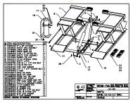
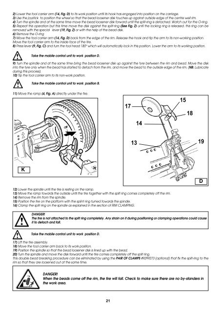
2) Lower the tool carrier arm (14, Fig. D) to its work position until its hook has engaged into position on the carriage.3) Use the joystick to position the wheel so that the bead loosener disk touches up against outside edge of the centre well rim.4) Turn the spindle and at the same time move the bead loosener disk forward until the split-ring is detached. Watch out for the O-ring.5) Repeat this operation but this time move the disk against the split-ring (See Fig. Z) until the locking ring is released. this ring can beremoved with the special lever (19, Fig. Z) or with the help of the bead disk.6) Remove the O-ring7) Move the tool carrier arm (14, Fig. D) back from the edge of the rim. Release the hook and tip the arm to its non-working position.Move the tool carrier arm to the inside face of the tire.8) Press lever (9, Fig. C) and turn the tool head 180° which will automatically lock in this position. Lower the arm to its working position.Take the mobile control unit to work position D.9) Turn the spindle and at the same time bring the bead loosener disk up against the tyre between the rim and bead. Move the diskinto the tyre only when the bead has started to detach from the rim, and move the bead to the outside edge of the rim. (NB: Lubricateduring this process).10) Tip the tool carrier arm to its non-work position.Take the mobile control unit to work position B.11) Move the ramp (4, Fig. A) directly under the tire.1714151813 19KD12) Lower the spindle until the tire is resting on the ramp.13) Move the ramp towards the outside until the tire together with the split ring comes completely off the rim.14) Remove the rim from the spindle.15) Position the tire on the platform with the splint ring turned towards the spindle.16) Clamp the split ring on the spindle as explained in the section of RIM CLAMPING.DANGER!The tire is not attached to the split ring completely. Any strain on it during positioning or clamping operations could causeit to detach and fall.Take the mobile control unit to work position D.17) Lift the tire assembly.18) Move the tool carrier arm back to its work position.19) Position the spindle so that the bead loosener disk is lined up with the bead.20) Turn the spindle and move the disk forward until the tire comes completely off the split ring.This double bead breaking procedure can be eliminated by using the pair of clamps #9299273 (optional) that fix the split-ring to therim so that they are loosened out at the same time.DANGER!When the beads come off the rim, the tire will fall. Check to make sure there are no by-standers inthe work area.21