18. MULTI-TYPE(V MULTI) PACKAGED AIR-CONDITIONER Split ...
18. MULTI-TYPE(V MULTI) PACKAGED AIR-CONDITIONER Split ...
18. MULTI-TYPE(V MULTI) PACKAGED AIR-CONDITIONER Split ...

Create successful ePaper yourself
Turn your PDF publications into a flip-book with our unique Google optimized e-Paper software.
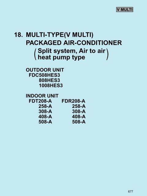
V <strong>MULTI</strong><strong>18.</strong> <strong>MULTI</strong>-<strong>TYPE</strong>(V <strong>MULTI</strong>)<strong>PACKAGED</strong> <strong>AIR</strong>-<strong>CONDITIONER</strong>(<strong>Split</strong> system, Air to air)heat pump typeOUTDOOR UNITFDC508HES3808HES31008HES3INDOOR UNITFDT208-A FDR208-A258-A 258-A308-A 308-A408-A 408-A508-A 508-A677
V <strong>MULTI</strong>CONTENTS<strong>18.</strong>1 GENERAL INFORMATION ...................................................................... 679<strong>18.</strong>1.1 Specific features ................................................................................ 679<strong>18.</strong>1.2 How to read the model name............................................................ 679<strong>18.</strong>1.3 Table of models ................................................................................. 680<strong>18.</strong>1.4 Table of system combinations ......................................................... 680<strong>18.</strong>2. SELECTION DATA ................................................................................... 681<strong>18.</strong>2.1 Specifications .................................................................................... 681<strong>18.</strong>2.2 Range of usage & limitations ........................................................... 688<strong>18.</strong>2.3 Exterior dimensions .......................................................................... 690<strong>18.</strong>2.4 Exterior appearance .......................................................................... 702<strong>18.</strong>2.5 Piping system .................................................................................... 703<strong>18.</strong>2.6 Selection chart ................................................................................... 705<strong>18.</strong>2.7 Characteristic of fan .......................................................................... 707<strong>18.</strong>2.8 Noise level .......................................................................................... 709<strong>18.</strong>3. ELECTRICAL DATA ................................................................................. 711<strong>18.</strong>3.1 Electrical wiring ................................................................................. 711<strong>18.</strong>4. OUTLINE OF OPERATION CONTROL BY MICROCOMPUTER ............ 713<strong>18.</strong>5. APPLICATION DATA................................................................................ 713<strong>18.</strong>5.1 Installation of indoor unit ................................................................ 713<strong>18.</strong>5.2 Installation of remote controller (Optional parts) ........................... 713<strong>18.</strong>5.3 Installation of outdoor unit ............................................................... 713<strong>18.</strong>6. MAINTENANCE DATA ............................................................................. 721678
V <strong>MULTI</strong><strong>18.</strong>1 GENERAL INFORMATION<strong>18.</strong>1.1 Specific featuresIdeal for the installation conditions characteristic of larger rooms and L-shaped or other non-standard-shaped rooms, the Multi-Type Vseries allows an extensive degree of flexibility in the selection of indoor units. Specifically, the selection of indoor units with differingcapacities and differing or similar types is supported, as is the selection of indoor units with similar capacities and differing types.Furthermore, a maximum of up to four individual indoor units can be operated in synchrony with a single outdoor unit.(1) Simaltaneous operation possible in non-standard-shaped rooms or large-sized areas.(2) Select indoor units of differing capacities and differing or similar types; alternatively, indoor units of similar capacities and differingtypes.(3) Up to four individual indoor units can be connected to single outdoor unit.(4) Indoor unit.(i) Ceiling recessed type (FDT)(a) All air supply ports have auto swing louvers. The indoor fan motor has two speeds of high and low.(b) All models have service valves protruding from the outdoor unit for faster flare connection work in the field.(c) Low sound levelOperating noise has been remarkably reduced due to adoption of the crescent turbo fan which cuts off wind-blowingnoise and also console type of cabinet which is highly effective to protect vibration.(d) 700mm high drain headAdoption of drain pump with high drain head and high capacity (600cc/min) has made it possible to have maximum700 mm(from below ceiling drain head.[In case 700mm drain head is required, set it up close to the unit. It is impossibleto do piping on down slope.](ii) Cassetteria type (FDR)(a) Quiet sound design(i) Noise reducing effect has been improved significantly with the employment of large silent steam fans which arefree from the wind swishing sound, and the special designing of noise shielding and acoustic suction panel.(ii) Ideal adaptation to the need for quiet sound at conference rooms, offices, etc.(b) 2 types of optional decorative panel(i) Optional decorative panel consists of silent panel and a canvas duct panel. [has smaller sizes and is prepared withcanvas duct panel which provides higher drain head.](ii) Flexibility of installation is increased with 2 type panels.(c) External static pressureHigh external static pressure type (Refer to the specification in clause 2 for the external static pressure.)<strong>18.</strong>1.2 How to read the model nameExample: FDT 20 8 - ASeries No.Example: FDC 80 8 H ES 3Nominal capacityFDT: Ceiling recessed type unit withModel name wired remote controllerFDR: Cassetteria type unit with wiredremote controllerApplicable power source ... See the specificationsHeat pump typeSeries No.Nominal capacityModel name (FDC: Outdoor unit)679
V <strong>MULTI</strong><strong>18.</strong>1.3 Table of modelsModelCapacity208 258 308 408 508Ceiling recessed type (FDT)Cassetteria type (FDR)Outdoor unit to be combined(FDC)FDC508HES3(5 Horse Power)FDC808HES3(8 Horse Power)FDC1008HES3(10 Horse Power)<strong>18.</strong>1.4 Table of system combinationsOutdoor unitTypeIndoor unit assembly capacityBranch pipe set(Optional)FDC508HES3Twin258+258 DIS-WAFDC808HES3Twin408+408308+508DIS-WBTriple308+308+308 DIS-TBDouble twin208+208+208+208DIS-WAº2setDIS-WBº1setFDC1008HES3TwinTriple508+508 DIS-WB208+408+408258+258+508 DIS-TB308+308+408Double twin 258+258+258+258DIS-WAº2setDIS-WBº1setNotes (1) It is possible to used different models (FDT, FDR) when combining indoor units.(2) Always use the branch piping set (optional) at branches in the refrigerant piping.680
V <strong>MULTI</strong><strong>18.</strong>2 SELECTION DATA<strong>18.</strong>2.1 Specifications(1) Indoor unit(a) Ceiling recessed type (FDT)Models FDT208-A, 258-AItemNominal cooling capacity (1)Nominal heating capacity (1)Power sourceNoise levelExterior dimensionsHeight Width DepthNet weightRefrigerant equipmentHeat exchangerRefrigerant controlAir handling equipmentFan type & Q'tyMotorStarting methodAir flow(Standard)Fresh air intakeAir filter, Q'tyShock & vibration absorberOperation controlOperation switchRoom temperature controlSafety equipmentInstallation dataRefrigerant piping sizeConnecting methodDrain hoseInsulation for pipingAccessoriesOptional partsModelWWdB(A)mmkgWCMMmm(in)FDT208-A50005400Hi: 38 Lo: 33Unit:215 700 700Panel:26 800 80023(Unit:18 Panel:5)30 1Hi: 14 Lo: 10Liquid line: 6.35 (1/4")Gas line: 15.88 (5/8")1 Phase 220/240V 50HzLouver fine & inner grooved tubingCapillary tubeTurbo fan 1Line startingAvailableLong life filter 1(Washable)Rubber sleeve(for fan motor)Remote control switch (Optional:RCD-H-S-E)Thermostat by electronicsInternal thermostat for fan motor.Frost protection thermostatFlare pipingConnectable with VP25Necessary (both Liquid & Gas line)Mounting kit, Drain hoseDecorative PanelFDT258-A57006100Hi: 39 Lo: 35Unit:260 840 840Panel:30 950 95030(Unit:24 Panel:6)25 1Hi: 16 Lo: 11Liquid line: 9.52 (3/8")Gas line: 15.88 (5/8")Notes(1) The data are measured at the following conditions.ItemIndoor air temperatureOutdoor air temperatureOperationDB WB DB WBCooling 2719 3524Heating 2076StandardsISO-T1,JIS B8616(2) This packaged air-conditioner is manufactured and tested in conformity with the following standard.JIS B8616"UNITARY <strong>AIR</strong>-<strong>CONDITIONER</strong>S"Decorative Panel model (Optional)ModelFDT208-AFDT258-AItemPanel Part No.T-PSA-22W-ET-PSA-32W-E681
V <strong>MULTI</strong>Models FDT308-A, 408-A, 508-AItemNominal cooling capacity (1)Nominal heating capacity (1)Power sourceNoise levelExterior dimensionsHeight Width DepthNet weightRefrigerant equipmentHeat exchangerRefrigerant controlAir handling equipmentFan type & Q'tyMotorStarting methodAir flow(Standard)Fresh air intakeAir filter, Q'tyShock & vibration absorberOperation controlOperation switchRoom temperature controlSafety equipmentInstallation dataRefrigerant piping sizeConnecting methodDrain hoseInsulation for pipingAccessoriesOptional partsModelWWdB(A)mmkgWCMMmm(in)FDT308-A7100100008000 112001 Phase 220/240V 50Hz30(Unit:24 Panel:6)FDT408-A34(Unit:28 Panel:6)Capillary tubeTurbo fan 180 1Line starting36(Unit:30 Panel:6)130 1Hi: 17 Lo: 12 Hi: 26 Lo: 19 Hi: 28 Lo: 20Liquid line: 9.52 (3/8")Gas line: 15.88 (5/8")Louver fine & inner grooved tubingAvailableLong life filter 1(Washable)Rubber sleeve(for fan motor)Remote control switch (Optional:RCD-H-S-E)Thermostat by electronicsInternal thermostat for fan motor.Frost protection thermostatFlare pipingConnectable with VP25Necessary (both Liquid & Gas lines)Mounting kit, Drain hoseDecorative PanelLiquid line: 9.52 (3/8")Gas line: 19.05 (3/4")FDT508-A1250014000Hi: 41 Lo: 35 Hi: 48 Lo: 40Hi: 49 Lo: 43Unit:260 840 840Unit:320 840 840Panel:30 950 950Panel:30 950 95030 1Notes(1) The data are measured at the following conditions.ItemIndoor air temperatureOutdoor air temperatureOperationDB WB DB WBCooling 2719 3524Heating 2076StandardsISO-T1,JIS B8616(2) This packaged air-conditioner is manufactured and tested in conformity with the following standard.JIS B8616"UNITARY <strong>AIR</strong>-<strong>CONDITIONER</strong>S"Decorative Panel model (Optional)ModelFDT308-A, 408-A, 508-AItemPanel Part No.T-PSA-32W-E682
V <strong>MULTI</strong>Models FDR308-A, 408-AItemDecorative panelPanel model (Option)Nominal cooling capacity (1)Nominal heating capacity (1)Power sourceNoise levelExterior dimensionsHeight Width DepthNet weightRefrigerant equipmentHeat exchangerRefrigerant controlAir handling equipmentFan type & Q'tyMotorStarting methodAir flow(Standard)Available static pressureFresh air intakeAir filter Q'tyShock & vibration absorberOperation controlOperation switchRoom temperature controlSafety equipmentInstallation dataRefrigerant piping sizeConnecting methodDrain hoseInsulation for pipingAccessoriesOptional partsModelWWdB(A)mmkgWCMMPa(mmAq)mm(in)Silent panelCanvas panelSilent panelCanvas panelR-PNLS-36W-E R-PNLC-36W-E R-PNLS-46W-E R-PNLC-46W-EUnit:355 950 635Panel:10 1240 750Unit:35Panel:8FDR308-A71008000100 1Unit:35Panel:6Standard:45(4.5), High:80(8.0)1 Phase 220/240V 50HzCapillary tubeLine startingUnit:50Panel:9Hi: 20 Lo: 15 Hi: 28 Lo: 22Internal thermostat for fan motor.Frost protection thermostatFDR408-A10000Hi: 44 Lo: 38 Hi: 45 Lo: 39 Hi:45 Lo: 38 Hi: 46 Lo: 39Unit:(299+α) 950 635Panel:10 1064 585Multiblade centrifugal fan 2Unit:50Panel:7Standard:50(5.0), High:80(8.0)AvailablePolypropylene net 2(Washable)Polypropylene net 3(Washable)Rubber sleeve(for fan motor)Liquid line: 9.52 (3/8")Gas line: 15.88 (5/8")Louver fins & inner grooved tubingRemote control switch (Optional:RCD-H-E)Thermostat by electronicsUnit:406 1370 635Panel:10 1660 750Flare pipingConnectable with VP25Necessary (both Liquid & Gas lines)Mounting kit, Drain hoseSilent panel, Canvas panel, Canvas duct11200Unit:(350+α) 1370 635Panel:10 1484 585Multiblade centrifugal fan 345 1+90 1Liquid line: 9.52 (3/8")Gas line: 19.05 (3/4")Notes (1)The data are measured at the following conditions.Item Indoor air temperature Outdoor air temperatureOperation DB WB DB WBCooling 2719 3524Heating 2076StandardsISO-T1,JIS B8616(2)This packaged air-conditioner is manufactured and tested in conformity with the following standard.JIS B8616"UNITARY <strong>AIR</strong>-<strong>CONDITIONER</strong>S"(3)Canvas panel is used in combination with following canvas ductCanvas duct: HA01503(4)Add the canvas duct lenght to the unit height for the canvas type.684
V <strong>MULTI</strong>ModelFDR508-AItemDecorative panelPanel model (Option)Nominal cooling capacity (1)Nominal heating capacity (1)Power sourceNoise levelExterior dimensionsHeight Width DepthNet weightRefrigerant equipmentHeat exchangerRefrigerant controlAir handling equipmentFan type & Q'tyMotorStarting methodAir flow(Standard)Available static pressureFresh air intakeAir filter Q'tyShock & vibration absorberOperation controlOperation switchRoom temperature controlSafety equipmentInstallation dataRefrigerant piping sizeConnecting methodDrain hoseInsulation for pipingAccessoriesOptional partsModelWWdB(A)mmkgWCMMPa(mmAq)mm(in)Silent panelR-PNLS-46W-EUnit:406 1370 635Panel:10 1660 750Unit:52Panel:9FDR508-A12500140001 Phase 220/240V 50HzCapillary tube50 1+100 1Line startingHi: 34 Lo: 27Standard:50(5.0), Hi speed:80(8.0)AvailablePolypropylene net 3(Washable)Rubber sleeve(for fan motor)Remote control switch (Optional:RCD-H-E)Thermostat by electronicsInternal thermostat for fan motor.Frost protection thermostatFlare pipingConnectable with VP25Necessary (both Liquid & Gas lines)Mounting kit, Drain hoseSilent panel, Canvas panel, Canvas ductCanvas panelR-PNLC-46W-EHi: 46 Lo: 39 Hi: 47 Lo: 40Louver fins & inner grooved tubingMultiblade centrifugal fan 3Liquid line: 9.52 (3/8"), Gas line: 19.05 (3/4")Unit:(350+α) 1370 635Panel:10 1484 585Unit:52Panel:7Notes(1)The data are measured at the following conditions.Item Indoor air temperature Outdoor air temperatureOperation DB WB DB WBCooling 2719 3524Heating 2076StandardsISO-T1,JIS B8616(2)This packaged air-conditioner is manufactured and tested in conformity with the following standard.JIS B8616"UNITARY <strong>AIR</strong>-<strong>CONDITIONER</strong>S"(3)Canvas panel is used in combination with following canvas ductCanvas duct: HA01484(4)Add the canvas duct lenght to the unit height for the canvas type.685
V <strong>MULTI</strong>Operation characteristics of each unit(Cooling/Heating)ModelItemFDC808HES3 FDT308-A FDT508-APower input (kW)Running current (A)8.44/6.4414.2/11.60.11/0.110.6/0.60.27/0.271.4/1.41 Total power input (kW)(Cooling) 8.44 + 0.11+ 0.27 = 8.82 (kW)(Heating) 6.44 + 0.11+ 0.27 = 6.82 (kW)2 Total running current (A)(Cooling) 14.2 + (0.6+1.4 × 2 .3) =. 15.5 (A)(Heating) 11.6 + (0.6 + 1.4 × 2 .3) =. 12.9 (A)3 Total power factor (%)(Cooling)(Heating)8.82 × 1000√ — 3 × 15.5 × 3806.82 × 1000√ — 3 × 12.9 × 380.× 100 =. 86 %.× 100 =. 80 %<strong>18.</strong>2.2 Range of usage & limitationsModelsAll modelsItemIndoor return air temperature(Upper, lower limits)Outdoor air temperature(Upper, lower limits)ModelAll modelsRefer to the selection chartIndoor unit atmosphere (behind ceiling)temperature and humidityRefrigerant line (one way) lengthVertical height difference betweenoutdoor unit and indoor unitPower source voltageVoltage at startingFrequency of ON-OFF cycleON and OFF intervalDew point temperature: 28˚C or less, relative humidity: 80% or lessRefer to the followingRating ± 10%Min. 85% of ratingMax. 10 times/hMax. 3 minutes688
V <strong>MULTI</strong>Height and length restrictions for refrigerant pipingModels FDC508HES3Outdoor unitLIndoor unitraArbB• One-way pipe length (m) L +ra +rb
V <strong>MULTI</strong><strong>18.</strong>2.3 Exterior dimensions(1) Indoor unit(a) Ceiling recessed type (FDT)Model FDT208-AFresh air openingfor ducting(Suspension bolts pitch)680B→570359C→740 (Ceiling hole size)430(Suspension boltspitch)Exhaust air openingfor ducting→D295336Unit : mmDecorative Panel800515Drain hose(Accessories)(Connectable with VP25)Suspension bolts(M10 or M8)1619949or moreLug for Suspension bolts300700Gas pipingφ15.88(5/8")264304→ALiquid pipingφ6.35(1/4")Hole for wiringControl box14126 215Air inlet grilleAir outlet grilleVIEW A295 ~ 325VIEW B700 or more(Max. Drain up)Holes fortapping screws4-φ4509090Holes fortapping screws704-φ414011035878012010037Space for installation and serviceObstacle1000or more1000or moreVIEW CVIEW D690
V <strong>MULTI</strong>Models FDT258-A, 308-AFresh airopening for ductingC↑860~890 (Ceiling hole size)780 (Suspension bolts pitch )Unit : mmDecorative Panel950630Exhaust airopening for ducting675 (Suspension bolts pitch)D→637422400420B→Drain hose (Accessories)(Connectable with VP25)332267310Liquid pipingφ9.52(3/8")Air outlet grilleVIEW AAir inlet grilleGas piping( φ15.88)840Suspension bolts(M10 or M8 ×4pcs.)295~3252109545 or moreLug forsuspension bolts↑AControl box137187260Hole for wiring30VIEW B700 or less(Max. Drain up)Holes fortapping screws4-φ45525Holes fortapping screws6-φ414060Space for installation and service11314080160 3311210042140Obstacle1000or more1000or moreVIEW CVIEW D691
V <strong>MULTI</strong>Models FDT408-A, 508-AUnit : mmDecorative PanelFresh airopening for ductingC↑860~890 (Ceiling hole size)780 (Suspension bolts pitch )950630Exhaust airopening for ducting675 (Suspension bolts pitch)D→637422400420B→Drain hose (Accessories)(Connectable with VP25)332267310Liquid pipingφ9.52(3/8")Air outlet grilleVIEW AAir inlet grilleGas pipingφ19.05(3/4")840Suspension bolts(M10 or M8 ×4pcs.)295~3252709545 or moreLug forsuspension bolts↑AControl box137187320Hole for wiring30VIEW B700 or less(Max. Drain up)Holes fortapping screws4-φ45525Holes fortapping screws6-φ414060Space for installation and service11314080160 9311210042140Obstacle1000or more1000or moreVIEW CVIEW D692
V <strong>MULTI</strong>(b)Cassetteria type (FDR)Model FDR208-ASilent Panel (Model: R-PNLS-26W-E)Unit : mm270 27557980 (Ceiling hole size)786 (Suspension bolts pitch)433353C↓Control boxPanel center1372846959Drain hose (Accessories)(Locality)45545(Suspension bolt pitch) 70690 (Ceiling hole size)150Fresh air opening(Knock out hole)405Air outlet duct714575Drain(Connectable with VP25)VIEW CGas pipingφ15.88 (5/8")Liquid pipingφ6.35 (1/4")Suspension bolts(M10 × 4pcs.)750185 320245295~325(Max. Drainup)355~36980 635510480465Hole for405humidifier piping(I.D. φ14)40232B→φ200MIN320650213163102↑ADrain (Natural drainage)(VP20)81460250Hole of wiring(I.D. φ35)φ149205 213Holes oftapping screws4-φ 4.045104095045150Air inlet4575φ170Fresh air openingfor ducting(Knock out hole)90φ170Exhaust air opening for ducting(Knock out for ducting)510750VIEW BSpace for installation and serviceAir inlet4575100 ormore1000or moreObstacle100 ormore50 ormoreVIEW A693
V <strong>MULTI</strong>ModelFDR208-ACanvas Panel (Model: R-PNLC-26W-E)Unit : mm804 (Ceiling hole size)9 786 (Suspension bolts pitch) 9Drain hose (Accessories)(Local Locality)525 (Ceiling hole size)545 (Suspension bolts pitch) 709045193 45352Panel centerC↓Control boxAir outlet duct284695971Drain(Connectable with VP25)Liquid pipingφ6.35 (1/4")150Fresh air opening(Knock out hole)405VIEW CGas pipingφ15.88 (5/8")Suspension bolts(M10 × 4pcs.)185750320245295~325(Max. Drain up)80Hole for humidifier piping(I.D.φ14)14963551048046540540Drain(Connectablewith VP25)130B→35600299274199260φ200Canvas duct(Optional parts)150~300Hole ofwiring(I.D.φ35)↑ADrain (Natural drainage)(VP20)460250φ149205 213Holes of tapping screws4-φ4.08641504577445φ170φ170Air inlet4575Fresh airopening for ducting(Knock out hole)90Exhaust air opening for ducting(Knock out hole)345585VIEW BSpace for installation and serviceAir inlet4575100 ormore1000or moreObstacle100 ormore50 ormoreVIEW A694
V <strong>MULTI</strong>Models FDR258-A, 308-ASilent Panel (Model: R-PNLS-36W-E)Unit : mm275270571180 (Ceiling hole size)986 (Suspension bolts pitch)533Panel centerC↓453Control box13728469594554545Drain hose (Accessories)(Locality)75 (Suspension bolts pitch) 70690 (Ceiling hole size)150Fresh air opening(Knock out hole)500VIEW CAir outlet duct71Suspension bolts(M10 × 4pcs.)B→φ200950165 285 285 215295~325(Max. Drain up)Hole forhumidifier piping(I.D.φ14)80635510480465405232MIN320650355~36921340163102↑ADrain (Natural drainage)(VP20)Gas pipingφ15.88 (5/8")Liquid pipingφ9.52 (3/8")81460250Holeof wiring(I.D.φ35)φ149205 213Holes oftapping screws4-φ4.04512401150 45150Air inlet4575φ170Fresh air openingfor ducting(Knock out hole)φ17090Exhaust air opening for ducting(Knock out hole)510750VIEW BSpace for installation and service100or more1000 ormore100 ormore50 ormoreAir inlet4575ObstacleVIEW A695
V <strong>MULTI</strong>Models FDR258-A, 308-A696
V <strong>MULTI</strong>Models FDR408-A, 508-ASilent Panel (Model: R-PNLS-46W-E)1600(Ceiling hole size)Drain hose(Accessories)1406(Suspension bolts pictch)137(Locality)57 743 663284C694570Fresh air opening(Knock out hole)Unit : mm270 275Panel centerControl box58545(Suspension bolts pictch)690(Ceiling hole size)150VIEW C4954575Air outlet duct7680 635Suspension bolts(M10 × 4 pcs.)φ2001370175 320 320 320235295~325(Max.Drain up)Drain(Connectablewith VP25)Hole forhumidifier piping(I.D.φ14)51048046540540MIN276BMIN320650406~420213163103ADrain(Natural drainage)(VP20)81Gas pipingφ19.05(3/4")460Liquid pipingφ9.52(3/8")155Hole ofwiring(I.D.φ35)φ149205 213Hole of tapping screws4 - φ4.0166045 1570 45Air inletφ170Fresh air openingfor ducting(Knock out hole)150φ17090Exhaust air opening for ducting(Knock out hole)45510 75750VIEW BSpace for installation and serviceAir inletVIEW A4575100 100 50or more or more or more1000or moreObstacle697
V <strong>MULTI</strong>Models FDR408-A, 508-ACanvas Panel (Model: R-PNLC-46W-E)Unit : mm90 525(Ceiling hole size)45 545(Suspension bolts pictch) 70352 193 45Suspension bolts(M10 × 4 pcs.)1424(Ceiling hole size)9 1406(Suspension bolts pictch)9Panel centerAir outlet ductC28469Control box59711370295~325175 320 320 320 235(Max.Drain up)Drain hose(Accessories)(Locality)150VIEW CFresh air opening(Knock out hole)49580 635Drain510(Connectablewith VP25)480Hole forhumidifier piping465(I.D.φ14)40520040130B →φ20086600350325250310Canvas duct(Optional parts)150~300Gas pipingφ19.05(3/4")Hole ofwiring(I.D.φ35)ADrain(Natural drainage)(VP20)Liquid pipingφ9.52(3/8")460155φ149205 213Hole of tapping screws4 - φ4.0148415045 139445Air inletφ170Fresh air openingfor ducting(Knock out hole)φ17090Exhaust air opening for ducting(Knock out hole)45345 75585VIEW BSpace for installation and serviceVIEW AAir inlet4575100 100 50or more or more or more1000or moreObstacle698
V <strong>MULTI</strong>(2) Remote controller (Optional parts)Unit : mm0.3mm 2 , 3cores (O.D.φ5.6)WallWire(Recessed)LCD displayJunction box(Locally Purchased)12016Remote controller mounting dimensions1208983.547For the passageafter wiring7604617120♦ Usable JIS box, JIS C 8336⋅ Switch box for 1 piece (without cover)(use of the mark hole as illustrated on the left)⋅ Switch box for 2 pieces(use of the mark hole as illustrated on the left)(without cover)(use of the mark hole as illustrated on the left)(when installing the cover)Notes (1) Allowable length of remote controllercable: 600 mAllowable rang of wire thickness and lengthRemote controller outlineStandard Within 0.3 mm 2 × Within 100 m0.5 mm 2 × Within 200 m0.75 mm 2 × Within 300 m1.25 mm 2 × Within 400 m2 mm 2 × Within 600 m699
V <strong>MULTI</strong>(3) Outdoor unitModel FDC508HES3Liquid piping: φ 9.52 (3/8")(Flare connecting)Gas piping: φ 19.05 (3/4")(Flare connecting)Unit: mm504610048Terminal block1250Liquid piping: φ 9.52 (3/8")(Flare connecting)Gas piping: φ 19.05 (3/4")(Flare connecting)Opening for electric wiringOpening forelectric wiringA10Opening for pipingand electric wiring9205550 1550 11019555557819550 110275050Opening for pipingand electric wiringHoles for anchor bolt(M10 × 4pcs.)165 580 17515 380 15340 3555355023747295501510315Holes for drain(φ 20 × 3pcs.)Electric wiringOpening for pipingand electric wiring15050 70154050Opening for electric wiringVIEW ARequired space for maintenance and air flowMinimum allowable space to the obstaclesL2AirinletMaintenancespaceL3L1Air inletAir outletL4MarkInstallationtype1 2 3Unit:mmL1 Open Open 500L2 300 5 OpenL3 150 300 150L4 5 5 5Notes(1) Avoid the location where four sides are entirelysurrounded by walls.(2) Fix the unit by anchor bolts without fail. Restrictthe protrusion length of anchor bolt to 15 mmand under.(3) When strong wind blows against the unit, directthe discharge port at a right angle to the winddirection.(4) Secure the space of 1 m and over at the top ofunit.(5) Make the height of obstruction wall in front ofdischarge port lower than the height of unit.700
V <strong>MULTI</strong>ModelsFDC808HES3, 1008HES3Unit: mm6005013501450Opening forexit wiring(ø50)Opening forexit piping(ø88)20Connect of liquid piping808: ø12.7 (1/2")( )1008: ø15.58 (5/8")291.5A17080105Power supply connectingterminal block119105Connect of gas piping808: ø25.4 (1")( )1008: ø28.58 (1 1/8")80170Opening forexit wiring(ø50)Opening forexit piping(ø88)Anchor bolts(M10 × 4pcs.)250 850 25040 767157Downward outlet hole forpiping and wiring640169395532Opening forexit liquidpipimg(ø25)15Opening forexit gas pipimg(ø39)1571581283.5567702283.5135123Hole for drain(8-ø20)Hole for drain(ø50)1022229VIEW ADimentions of refrigerant pipingconnecting mouth(Front)Opening forexit wiring(ø35)50Opening for exitgas pipimg(ø65)Rear surfaceConnect ofgas piping808: ø25.4 (1")( 1008: ø28.58 (1 1/8") )17517524011011088123808: ø12.7 (1/2")( )70100Opening forexit liquid piping(ø50)Connect of liquid piping1008: ø15.88 (5/8")Wall height H2Wall Height H3Unit:mmsuctionL2 L4I II IIIInstallationexampleDimensionsL1 Open Open 500Service( )spaceWall height H1L1 L3Wall height H4L2L3L4H1H2H3H40300Open030050030001000 or lessNot limited Not limited Not limitedNot limited Not limited 700 or lessNot limited Not limitedNotes (1) Make sure to secure the unit with anchor bolts.(2) When the strong wind blows, place the unit so that dischargeoutlet faces the wind direction with right angle.(3) Make sure to allow the space of 1 m or more above theunit.(4) Connect the refrigerant piping (both gas side and liquidside) at local site.(5) If the wall height H1, H3 of installation example IIIexceeds the limited value, make sure the value of L1, L3are to be as follows.L1 =H1 -500L3 = 300 + (H3-700) / 2, however, if L3 exceeds 600, thereis no limit for the wall height H3.0701
V <strong>MULTI</strong><strong>18.</strong>2.4 Exterior appearance(1) Indoor unit(a) Ceiling recessed type (FDT)Models All modelsTypeItem Panel model RemarksFDT208-AFDT258-A~508-AT-PSA-22W-ET-PSA-32W-EWithout swingPearl white(Decorative panel)(b)Cassetteria type (FDR)Models All modelsSilent panel typeCanvas-duct panel typeCeramic WhiteCeramic White(2) Outdoor unitModel FDC508HES3ModelsFDC808HES3, 1008HES3Polar whitePolar white702
V <strong>MULTI</strong><strong>18.</strong>2.5 Piping system(1) Twin typeModel FDC508HES3Indoor unitIndoor unitHigh pressure switch (63H2)(For fan motor control)Cooling cycleHeating cycleOutdoor unit(ø15.88)(ø15.88)4way valveThermistor(ThO-A)StrainerStrainerBranch pipe(Brazing)Flare connectingGas line(ø19.05)Service valve(Flare connecting)Check jointThermistor(ThI-A)Check jointOil separatorCapillary tubeHeat exchangerHeat exchangerThermistor(ThO-D)Capillarytube(ø9.52)CapillarytubeThermistor(ThI-R)Flare connecting(ø9.52)Liquid line(ø9.52)CheckjointCompressorSolenoidvalve (SV1)CapillarytubeCapillarytubeStrainerAccumulatorsSolenoidvalve (SV2)Check valveThermistor(ThO-R)SubcoolingcoilStrainerStrainerBranchpipe(Brazing)StrainerService valve(Flare connecting)Capillary tubeNote (1) Refer to page 715 for piping size after branching.Models FDC808HES3,1008HES3Indoor unitIndoor unitFlare connectingBranchpipe (Brazing)Service valve(Brazing)High pressure switch(63H2)(For fan motor control)Cooling cycleHeating cycleThermistor(ThO-A)Outdoor unitStrainer308 : ø15.88( )408,508 : ø19.05Strainer308 : ø15.88( )408,508 : ø19.05Thermistor(ThI-A)HeatexchangerGsa line808 : ø25.4( 1008 : ø28.58)High pressureswitch(63H1)(For protection)4way valveMufflerHeatexchangerLowerUpperThermistor(ThI-R)MufflerCompressorAccumlatorThermistor (ThO-R)Only case of FDC808HES3(ø9.52)Capillary tube(ø9.52)Liquid line808 : ø12.7( 1008 : ø15.88)Capillary tubeCheck valveThermistor (ThO-R)Only case of FDC1008HES3StrainerStrainerBranchpipe(Brazing)Service valve(Flare connecting)Capillary tubeNote (1) Refer to page 716 for piping size after branching.703
V <strong>MULTI</strong>(2) Triple typeModels FDC808HES3,1008HES3Indoor unitStrainer( )208~308 : ø15.88408, 508 : ø19.05Indoor unitStrainer( )208~308 : ø15.88408, 508 : ø19.05Indoor unitStrainerFlareconnecting( )208~308 : ø15.88408, 508 : ø19.05Branchpipe(Brazing)Gsa line808 : ø25.41008 : ø28.58( )Service valve(Brazing)Cooling cycleHeating cycleHigh pressure switch(63H2)(For fan motor control)Thermistor(ThO-A)Outdoor unitThermistor(ThI-A)HeatexchangerHigh pressureswitch(63H1)(For protection)4way valveMufflerHeatexchangerLowerUpperThermistor(ThI-R)MufflerCompressorAccumlatorThermistor (ThO-R)Only case of FDC808HES3( )208: ø6.35258~508 : ø9.52( )208: ø6.35258~508 : ø9.52Capillary tube( )208: ø6.35258~508 : ø9.52Branchpipe(Brazing)Liquid line808 : ø12.7( 1008 : ø15.88)Capillary tubeCheck valveThermistor (ThO-R)Only case of FDC1008HES3StrainerStrainerStrainerFlareconnectingService valve(Flare connecting)Capillary tubeNote (1) Refer to page 716 for piping size after branching.(3) Dauble twin typeModels FDC808HES3,1008HES3Indoor unitStrainerIndoor unit(¿15.88) Strainer (¿15.88)Thermistor(ThI-A)HeatexchangerThermistor(ThI-R)Flare connectingBranchpipe (Brazing)Secondarybranch pipe(¿15.88)First branchpipe(¿19.05)First branch pipe(¿19.05)Branch pipe(Brazing)Gsa line808 : ¿25.41008 : ¿28.58( )Service valve(Brazing)High pressureswitch(63H1)(For protection)MufflerHigh pressure switch(63H2)(For fan motor control)4way valveMufflerCompressorCooling cycleHeating cycleAccumlatorThermistor(ThO-A)HeatexchangerLowerUpperThermistor (ThO-R)Only case of FDC808HES3Strainer208 : ¿6.35( 258 : ¿9.52 )StrainerCapillary tube208 : ¿6.35( 258 : ¿9.52 )Secondarybranch pipe(¿9.52)Branchpipe(Brazing)Branch Liquid linepipe 808 : ¿12.7(Brazing) ( 1008 : ¿15.88 )Service valve(Flare connecting)Capillary tubeCheck valveCapillary tubeThermistor (ThO-R)Only case of FDC1008HES3Indoor unitIndoor unitFlare connectingBranchpipe (Brazing)Strainer(¿15.88) Strainer (¿15.88)Thermistor(ThI-A)HeatexchangerThermistor(ThI-R)Capillary tube208( 258 ): ¿6.35: ¿9.52208 : ¿6.35( 258 : ¿9.52 )Note (1) Refer to page 717 for piping size after branching.StrainerStrainerBranchpipe(Brazing)704
V <strong>MULTI</strong>Preset point of the protective devicesParts nameMarkEquippedunitFDC508HES3FDC808HES3, 1008HES3Thermistor(for protection overloadingin heating)ThI-RIndoor unitOFF 68˚CON 61˚CThermistor(for frost prevention)OFF 2.5˚CON 10˚CThermistor(for detecting dischargepipe temp.)Tho-DOutdoor unitOFF 135˚CON 90˚CThermistor(for detecting heatexchange temp.)Tho-ROutdoor unitOFF 70˚CON 60˚CHigh pressure switch(for controlling FM0)63H2OFF 2.5MPa (25.5 kgf/cm 2 ) OFF 2.75MPa (28 kgf/cm 2 )ON 2.06MPa (21 kgf/cm 2 ) ON 2.16MPa (22 kgf/cm 2 )High pressure switch(for protection)63H1Outdoor unitOFF 2.41MPa (24.5 Kgf/cm 2 )ON 1.86MPa (19.0 kgf/cm 2 )<strong>18.</strong>2.6 Selection chartCorrect the cooling and heating capacity in accordance with the conditions as follows. The net cooling and heating capacity can beobtained in the following way.Net capacity = Capacity shown on specifications × Correction factors as follows.(1) Coefficient of cooling and heating capacity in relation to temperaturesHeating operation Cooling operation Coefficient of cooling and heating capacityin relation to temperaturesOutdoor air D.B.temperature (˚CD.B.)Indoor air D.B.temperature (˚CD.B.)Indoor air W.B. temperature (˚CW.B.) ISO-T1 Standard conditionOutdoor air W.B. temperature (˚CW.B.) ISO-T1 Standard condition705
V <strong>MULTI</strong>Table of bypass factorFDT seriesItemAir flowModel208 type 258 type 308 type 408 type 508 typeHi 0.112 0.050 0.065 0.076 0.025Lo 0.073 0.030 0.030 0.050 0.013FDR seriesItemModel208 type 258 type 308 type 408 type 508 typeAir flowHi 0.035 0.035 0.039 0.085 0.035Lo 0.021 0.020 0.023 0.060 0.023(2) Correction of cooling and heating capacity in relation to air flow rate control (fan speed)Coefficient: 1.00 at High, 0.95 at Low(3) Correction of cooling and heating capacity in relation to one way length of refrigerant pipingIt is necessary to correct the cooling and heating capacity in relation to the one way equivalent piping length between the indoorand outdoor units.Equivalent piping length (1) m 5 10 15 20 25 30 35 40 45 50 55Heating 1.0 1.0 1.0 1.0 1.0 0.995 0.995 0.99 0.99 0.985 0.985CoolingFDC508 typeFDC808, 1008 type1.0 0.99 0.975 0.965 0.95 0.94 0.925 0.915 0.9 0.89 0.8751.0 0.99 0.98 0.97 0.96 0.95 0.94 0.93 0.92 0.91 0.9Note (1)Equivalent piping length can be obtained by calculating as follows.508 series [φ19.05 (3/4″)] : Equivalent piping length = Real piping length + (0.15 × Number of bends in piping)808 series [φ25.4 (1″)] : Equivalent piping length = Real piping length + (0.15 × Number of bends in piping)1008 series [φ28.58 (1 1/8″)] : Equivalent piping length = Real piping length + (0.20 × Number of bends in piping)[Equivalent piping length < Limitation length of piping + 5m](4) When the outdoor unit is located at a lower height than the indoor unit in cooling operation and when theoutdoor unit is located at a higher height than the indoor unit in heating operation, the following values should besubtracted from the values in the above table.Height difference between the indoor unit andoutdoor unit in the vertical height difference5m 10m 15m 20m 25m 30mAdjustment coefficient 0.01 0.02 0.03 0.04 0.05 0.06Piping length limitationsModelItemMax. one way piping lengthMax. vertical height differenceAll models50mOutdoor unit is higher 30mOutdoor unit is lower 15mNote (1)Values in the table indicate the one way piping length between the indoor and outdoor units.How to obtain the cooling and heating capacityExample : The net cooling capacity of the model FDC808HES3 with the air flow “High”, the piping length of 40m, the outdoor unitlocated 5m lower than the indoor unit, indoor wet-bulb temperature at 19.0 ˚C and outdoor dry-bulb temperature 35 ˚C isNet cooling capacity = 20000 × 1.00 × (0.93 - 0.01) × 1.0 = 18400 w706FDC808HES3Air flow“High”Length m.Height difference 5 mFactor by airtemperatures
V <strong>MULTI</strong><strong>18.</strong>2.7 Characteristics of fan• External static pressure table How to interpret the blower characteristics tableUnit: Pa (mmAq)Example : Case of FDR308-ATypeDuct specs. 1 spot closing (1) Standard (2) Square duct (3)Air flow(m 3 /min)FDR208-AFDR258-AFDR308-AFDR408-AFDR508-A1418202834Highspeed (4)Highspeed (4)StandardStandardStandardHighspeed (4)— — 50(5) 85(8.5) 50(5) 90(9)30(3) 65(6.5) 45(4.5) 80(8) 50(5) 85(8.5)25(2.5)40(4)60(6)70(7)45(4.5)50(5)80(8)80(8)50(5)50(5)85(8.5)85(8.5)40(4) 70(7) 50(5) 80(8) 55(5.5) 85(8.5)Notes (1) 1 spot closing: Round duct flange at center is removed and shieldwith a decorative panel (option).(2) Standard: ø200 ducts are installed at all blowout holes.(3) Square duct: All round ducts are removed and replaced with specialsquare duct flanges (option).(4) When operating at a high speed, invert the connection of whiteand red connectors on the flank of control box.Static pressure Pa (mmAq)40(4)20(2)0(0)Standard •Low2-spots blowerinternal resistance[Standard]3-spot blowerinternal resistanceSquare duct blower internal resistance–2(–2)Internal resistance without suction panel14Internal resistance without filter• High17 20 22Air flow (m 3 /min)1 2-spot blowout.....................Internal resistance increases morethan the standard 3-spot blowout.Approx. 14 (1.4) Pa (mmAq) at17m 3 /min.2 Square duct blowout...........Internal resistance decreasesmore than the standard roundduct (ø200 3-spot). 3 (0.3) Pa(mmAq) at 17 m 3 /nin. (Externalstatic pressure increases inreverse.).3 Decorative panel...................When the decorative panel is notused with the ceiling return type,the part of internal resistancerelated to the panel decrease. 3(0.3) Pa (mmAq) at 17mm 3 /min.ModelFDR208-AModelFDR258-A120(12)120(12)Static pressure Pa (mmAq)100(10)80(8)60(6)40(4)20(2)High speed •LowHigh speed •Upper limitStandard •Upper limitStandard • LowHigh speed • HighHigh speed •Lower limitStandard • HighStatic pressure Pa (mmAq)100(10)80(8)60(6)40(4)20(2)High speed • Upper limitStandard •Upper limitHigh speed •LowStandard • LowHigh speed • HighStandard • HighHigh speed • Lower limit0(0)0(0)2-spot blower internal resistance[Standard] 2-spot blower internal resistance–20(–2)10LowerlimitSquare duct blower internal resistanceInternal resistance without suction panelInternal resistance without filter12 14 15.5UpperAir flow (m 3 /min) limit[Standard]–20(–2)13Lowerlimit3-spot blower internal resistanceSquare duct blower internal resistanceInternal resistance without suction panelInternal resistance without filter14 16 18 20UpperAir flow (m 3 /min) limit707
V <strong>MULTI</strong>Model FDR308-A Model FDR408-A120(12)120(12)100(10)80(8)High speed •Upper limit100(10)80(8)High speed • Upper limitStatic pressure Pa (mmAq)60(6)40(4)20(2)Standard •Upper limitStandard •LowHigh speed •LowHigh speed •HighStandard •HighHigh speed •Lower limitStatic pressure Pa (mmAq)60(6)40(4)20(2)Standard •Upper limitHigh speed •LowStandard • LowHigh speed •HighHigh speed •Lower limitStandard • High0(0)2-spot blowerinternal resistance0(0)3-spot blower internal resistance[Standard] 4-spot blower internal resistance–20(–2)[Standard]3-spot blower internal resistance14LowerlimitSquare duct blower internal resistanceInternal resistance without suction panelInternal resistance without filter17 20 22UpperAir flow (m 3 /min) limit–20(–2)21LowerlimitSquare duct blowerinternal resistanceInternal resistance without suction panelInternal resistance without filter22 2528 31Air flow (m 3 /min)UpperlimitModel120(12)FDR508-A100(10)High speed •Upper limitHigh speed •HighStatic pressure Pa (mmAq)80(8)60(6)40(4)20(2)Standard •Upper limit3-spot blowerinternal resistanceStandard • LowHigh speed •LowHigh speed •Lower limit0(0)4-spot blower internal resistance [Standard]708–20(–2)24LowerlimitSquare duct blower internal resistanceInternal resistance without suction panelInternal resistance without filter26 30 34 38UpperAir flow (m 3 /min)limit
V <strong>MULTI</strong><strong>18.</strong>2.8 Noise levelNotes(1) The data are based on the following conditions.Ambient air temperature:Indoor unit 27˚C DB, 19˚C WB.Outdoor unit 35˚C DB.Indoor unitMeasured based on JIS B 8616Mike position as belowFDT seriesMike (center & low points)FDR seriesSilent panel1.5mUnitCanvas panelOutdoor unitOnly case of FDC508Measured based on JIS B 8616Mike position: at highest noise levelin position as belowDistance from front side 1 mHeight1 mOnly case of FDC808, 1008Mike position: front height is 1 meter.(2) The data in the chart are measured in an unechonic room.(3) The noise levels measured in the field are usually higher than the data because of reflection.1.5mUnit(1) Indoor unit(a) Ceiling recessed type (FDT)Sound pressure level(Standard 0.0002µ bar) dBModel7060504030ModelFDT208-ANoise level 38 dB (A) at HIGH33 dB (A) at LOWN20Mid octave band frequency (Hz)FDT408-ANoise levelN70N60N50N40N30202063 125 250 500 1000 2000 4000 8000706050403048 dB (A) at HIGH40 dB (A) at LOWSound pressure level(Standard 0.0002µ bar) dBModel7060504030ModelFDT258-ANoise levelMid octave band frequency (Hz)FDT508-ANoise levelN2039 dB (A) at HIGH35 dB (A) at LOWN70N60N50N40N30202063 125 250 500 1000 2000 4000 8000706050403049 dB (A) at HIGH43 dB (A) at LOWModelSound pressure level(Standard 0.0002µ bar) dB7060504030FDT308-ANoise level41 dB (A) at HIGH35 dB (A) at LOWN20Mid octave band frequency (Hz)N70N60N50N40N30202063 125 250 500 1000 2000 4000 8000706050403070N707070N7070Sound pressure level(Standard 0.0002µ bar) dB60504030N20Mid octave band frequency (Hz)N60N50N40N30202063 125 250 500 1000 2000 4000 800060504030Sound pressure level(Standard 0.0002µ bar) dB60504030N20Mid octave band frequency (Hz)N60N50N40N30202063 125 250 500 1000 2000 4000 800060504030(b)Cassetteria type (FDR)1) Silent panelModelFDR208-AModelFDR258-AModelFDR308-A70Noise level43 dB (A) at HIGH37 dB (A) at LOWN707070Noise level43 dB (A) at HIGH37 dB (A) at LOWN707070Noise level44 dB (A) at HIGH38 dB (A) at LOWN7070Sound pressure level(Standard 0.0002µ bar) dB60504030N20Mid octave band frequency (Hz)N60N50N40N30202063 125 250 500 1000 2000 4000 800060504030Sound pressure level(Standard 0.0002µ bar) dB60504030N20Mid octave band frequency (Hz)N60N50N40N30202063 125 250 500 1000 2000 4000 800060504030Sound pressure level(Standard 0.0002µ bar) dB60504030N20Mid octave band frequency (Hz)N60N50N40N30202063 125 250 500 1000 2000 4000 800060504030709
V <strong>MULTI</strong>ModelFDR408-AModelFDR508-A70Noise level45 dB (A) at HIGH38 dB (A) at LOWN707070Noise level46 dB (A) at HIGH39 dB (A) at LOWN7070Sound pressure level(Standard 0.0002µ bar) dB60504030N20N60N50N40N30202063 125 250 500 1000 2000 4000 8000Mid octave band frequency (Hz)60504030Sound pressure level(Standard 0.0002µ bar) dB60504030N20Mid octave band frequency (Hz)N60N50N40N30202063 125 250 500 1000 2000 4000 8000605040302) Canvas panelModelFDR208-AModelFDR258-AModelFDR308-A70Noise level44 dB (A) at HIGH38 dB (A) at LOWN707070Noise level44 dB (A) at HIGH38 dB (A) at LOWN707070Noise level45 dB (A) at HIGH39 dB (A) at LOWN7070Sound pressure level(Standard 0.0002µ bar) dB60504030N20N60N50N40N30202063 125 250 500 1000 2000 4000 8000Mid octave band frequency (Hz)60504030Sound pressure level(Standard 0.0002µ bar) dB60504030N20Mid octave band frequency (Hz)N60N50N40N30202063 125 250 500 1000 2000 4000 800060504030Sound pressure level(Standard 0.0002µ bar) dB60504030N20Mid octave band frequency (Hz)N60N50N40N30202063 125 250 500 1000 2000 4000 800060504030ModelFDR408-AModelFDR508-A70Noise level46 dB (A) at HIGH39 dB (A) at LOWN707070Noise level47 dB (A) at HIGH40 dB (A) at LOWN7070Sound pressure level(Standard 0.0002µ bar) dB60504030N20N60N50N40N30202063 125 250 500 1000 2000 4000 8000Mid octave band frequency (Hz)60504030Sound pressure level(Standard 0.0002µ bar) dB60504030N20Mid octave band frequency (Hz)N60N50N40N30202063 125 250 500 1000 2000 4000 800060504030(2) Outdoor unitModelFDC508HES3ModelFDC808HES3ModelFDC1008HES3Noise level55 dB (A)Noise level58 dB (A)Noise level58 dB (A)70N707070N707070N7070Souud pressure level(standard 0.0002µbar)60504030N20Mid octave band frequency (Hz)N60N50N40N30202063 125 250 500 1000 2000 4000 800060504030Sound pressure level(Standard 0.0002µ bar) dB60504030N20Mid octave band frequency (Hz)N60N50N40N30202063 125 250 500 1000 2000 4000 800060504030Sound pressure level(Standard 0.0002µ bar) dB60504030N20Mid octave band frequency (Hz)N60N50N40N30202063 125 250 500 1000 2000 4000 800060504030710
<strong>18.</strong>3 ELECTRICAL DATA<strong>18.</strong>3.1 Electrical wiring(1) Indoor unit(a) Ceiling recessed type (FDT)Models All models(b)Power wiresto outdoor unitto outdoor unitMeaning of marksMarkParts nameFMI Fan motor (indoor unit)49FI Internal thermostat for FMICFI Capacitor for FMILM Louver motorLS Limit switchDM Drain motorFS Float switchX1 Auxiliary relay (for LM)X2 Auxiliary relay (for DM){{TB123Cassetteria type (FDR)Models All modelsPower wiresto outdoor unitto outdoor unit{{TB12345RDWHBKBLBRY / GN4511191014RDWHBKBLBRY / GNX5PCX61291014Y / GNRDLX5PCBL BLBKX6BR BRLMWHX1OR ORRD RDCnJFMI2 OR(49FI)ORCnF5 CnF5CnSWHY / GNX3X43 8 7 6BLBKBLBKL H UH ORFMI(49FI)WHWHWH5CnF1X7CFIBR BRDMWHWHX24 13GRCnJ CnF1CnR CnIY / GNCnF3CnF5M H UHCFI2WHRDRDX3BLCnF4BKBKBKFMI1(49FI)CnF2BRX4X1X2X3ORCnF4X78 7 6RD/WH BL/WH BK/WHLCnF2CnF4M H UHORCnF3WHX4X5X6CFI1X1X2X35X7X4X5X6CnRX7PCWH RDRDFSCnIVal220/240VTr IBK RD12VBKCnW1CnQTestBR CnW2ON SW21 2 3 4OFFON SW31 2 3 4OFFCnTCnHCnNCnSCnBPrinted circuit boardX1BR/WHBK BKDMBKWH BRX23 4 13GRCnRICnRCnRCnRIPCWH BR RDRD RDCnRICnIFSCnICnRIVal220/240VCnH2BK BKBK BKRDRDBKXR2XR4CnNBKBKCnS2BKXR1XR3XR5BK BKRDXWHYBKZTr IBK RD12VBKCnW1CnQTestBR CnW2ON SW31 2 3 4OFFCnTCnHCnNCnBPrinted circuit boardNote(1) "FMI2" and the following wires (shown in ) are equipped only for FDR408, 508.Meaning of marksColor markMarkFMI1, 249FICFI1, 2DMFSX1X2X3 4, 7Parts nameFan motor (indoor unit)Internal thermostat for FMICapacitor for FMIDrain motorFloat switchAuxiliary relay (for LM)Auxiliary relay (for DM)Auxiliary relay (for FMI)MarkParts nameX3, 4, 7 Auxiliary relay (for LM)X5 Auxiliary relay (for 52C)X6 Auxiliary relay (for 20S, 52Fo)Thc ThermistorThI-A ThermistorThI-R ThermistorTrI TransformerVaI VaristorPC Photo couplerMarkParts nameX5 Auxiliary relay (for 52C)X6 Auxiliary relay (for 20S, 52Fo)Thc ThermistorThI-A ThermistorThI-R ThermistorTrI TransformerVaI VaristorPC Photo couplerMarkCnA-WTB■vLED-1LED-2SW2, 3MarkCnA-WTB■vLED-1LED-2SW1SW3Parts nameConnectorTerminal blockConnectorTerminal (F)Indication lamp (Green-Run)Indication lamp (Yellow-Check)Changeover switchParts nameConnectorTerminal blockConnectorTerminal (F)Indication lamp (Green-Run)Indication lamp (Yellow-Check)Switch (Address set)Changeover switchColor markMark ColorBK BlackBL BlueBR BrownGR GrayOR OrangeRD RedMarkBKBLBRGRORRDSW1ColorBlackBlueBrownGrayOrangeRedLSV <strong>MULTI</strong>ThI–AThI–ROptionX Y ZRD WH BKThcRemotecontrollerCnH2BK BKBK BKRDRDRDWHBKXR2XR4CnNBKBKXR1XR3XR5TBXYZMarkWHY/GNRD/WHBL/WHBK/WHBR/WHThI–AThI–ROptionX Y ZRD WH BKThcRemotecontrollerColorWhiteYellow/GreenRed/WhiteBlue/WhiteBlack/WhiteBrown/White711
V <strong>MULTI</strong>(2) Outdoor unitModel FDC508HES3Power source3Phase 380-415V 50HzTBTBRDL1WHL2RD/WHBK/WH12/NBLL3BK/RDBK/WH3NNRBL/WH41 3 5BR/WH552C2 4 6Y/GNRDCT1RDX01X04X07WHBLWHX02X05X08CT2BLVU WCMX03X06WHBK/WHPrinted Circuit BoardRDRD/WH1 2 3 28F(3.15A)HCnM1X02L UHFMO1(49FO1)BKBLBRWHORORX03 X04CF01OR/WHOR/WH12 13HCnM2L UHFMO2(49FO2)BKBKBKBLBRWHORORGRCF02GR14 15BK16X0520SBK17CHBRCnRBRX0152CA1 A2PPBLSV1BLBLSV2BLBR/WHBK/RDBL/WH18 19 20 21 22 23 25 26 27X06 X08 X07PCPCDRCnE(Checker)Vao663H2DRTho-R Tho-D Tho-ABKCnLLED-R(Check)CnA1 CnA2LED-G14V220/240V7TroBK(Run)BKY/GNPower wires} to indoor unit}to indoor unitMeaning of marksMarkParts nameMeaning of marksMarkParts nameCMCompressor motorLED-R Indication lamp (Red)FMo1,2 Fan motor (outdoor unit) CT1,2 Current sensor52CMagnetic contactor for CM Tho-R Thermistor (outdoor H.Ex.temp.)49Fo1,2 Internal thermostat for FMo Tho-D Thermistor (discharge temp.)CHCrankcase heaterTho-A Thermistor (outdoor air temp.)CFo1,2 Capacitor for FMoTroTransformerXo1~8 Auxiliary relayVaoVaristor63H2High pressure switch (for control) PCPhoto coupler20S4 way valve solenoid coil CnA~R ConnectorSV1,2 Solenoid coil (for control) TBTerminal blockFFuse (3.15A)NRSurge suppressorLED-G Indication lamp (Green)Color markMark ColorBK BlackBL BlueBR BrownGR GrayOR OrangeP PinkRD RedWH WhiteMarkBK/RDBK/WHBL/WHBR/WHOR/WHRD/WHY/GNColorBlack/RedBlack/WhiteBlue/WhiteBrown/WhiteOrange/WhiteRed/WhiteYellow/GreenModels FDC808HES3, 1008HES3Power source3Phase 380-415V 50HzTBRDL1WHL2BLL3BK/WHNY/GN1 352C2 4RDCT1RDX01X04X07UWHBLWHVCMX02X0556WCT2BLX03F(3.15A)WH1BK/WH2RD3F(3.15A)28X02H LCnM1X03FMO1(49FO1)F(5A)X04CF01BKBLWHOROROR/WHOR/WH1213HBKCnM2FMO2(49FO2)WHOROR20S 52CCF02A1 A2GRGRGRGRBRCHBRPP14 15 16 17X05CnR18 19 20X012122BR/WHBK/RDBL/WH23 25 26 27X07PCPCORCnE(Checker)Vao49C63H1OR8 9OR663H2ORRDRD/WHBK/WHBK/RDBL/WHBR/WHTho-RTho-ACnLLED-G(Normal)CnA1 CnA2LED-R14V220/240V7CnQ(Test)(Check)YTB1Y/GN2/N345Power wires} to indoor unit}to indoor unitPrinted Circuit BoardTroMeaning of marksMarkParts nameMeaning of marksMarkParts nameCMCompressor motorLED-G Indication lamp (Green)FMo1,2 Fan motor (outdoor unit) LED-R Indication lamp (Red)52CMagnetic contactor for CM CT1,2 Current sensor49CInternal thermostat for CM Tho-R Thermistor (outdoor H.Ex.temp.)49Fo1,2 Intrnal themostat for FMo Tho-A Thermistor (outdoor air temp.)CHCrankcase heaterTroTransformerCFo1,2 Capacitor for FMoVaoVaristorXo1~7 Auxiliary relayPCPhoto coupler63H1High pressure switch (for protection) CnA~R Connector63H2High pressure switch (for control) TBTerminal blockFFuseColor markMark ColorBK BlackBL BlueBR BrownGR GrayOR OrangeP PinkRD RedWH WhiteMarkBK/RDBK/WHBL/WHBR/WHOR/WHRD/WHY/GNColorBlack/RedBlack/WhiteBlue/WhiteBrown/WhiteOrange/WhiteRed/WhiteYellow/Green712
V <strong>MULTI</strong><strong>18.</strong>4 OUTLINE OF OPERATION CONTROL BY MICROCOMPUTERExcept for function relating to heating, same as the unit for FDT(N) heat pump type. See page 317.<strong>18.</strong>5 APPLICATION DATA<strong>18.</strong>5.1 Installation of indoor unit(1) Ceiling recessed type (FDT)Except for function relating to heating, same as the unit for FDT(N) heat pump type. See page 333.(2) Cassetteria type(FDR)Except for function relating to heating, same as the unit for FDR heat pump type. See page 571.<strong>18.</strong>5.2 Installation of remote controller(Optional parts)Except for function relating to heating, same as the unit for FDT(N) heat pump type. See page 337.<strong>18.</strong>5.3 Installation of outdoor unitOWARNINGBE SURE TO READ THESE INSTRUCTIONS CAREFULLY BEFORE BEGIN-NING INSTALLATION. FAILURE TO FOLLOW THESE INSTRUCTIONS COULDCAUSE SERIOUS INJURY OR DEATH, EQUIPMENT MALFUNCTION AND/OR PROPERTY DAMAGE.(1) Installation(a)AccessoriesConfirm accessories shown below are attached in the bag with this installation manual.1) “Edging” for protection of electric wires from opening edge.(b)Selection of installation locationSelect the installation location after obtaining the approval of customer.1) The place where the foundation can bear the weight of Outdoor unit.2) The place where there is no concern about leakage of combustible gas.3) The place where it is not stuffy.4) The place where free from thermal radiation of other thermal source.5) The place where flow of drain is allowed.6) The place where noise and hot air blast do not trouble neighboring houses.7) The place where there is no obstruction of wind at the intake air port and discharge air port.713
V <strong>MULTI</strong>8) When the unit is installed at the particular location as shown below, corrosion or failure may be caused. Please consultthe dealer from which you purchased the air-conditioner.a) The place where corrosive gas is generated (hot spring, etc.).b) The place where wind containing salt blows (seaside area).c) The place where enveloped by oil mist.d) The place where there is a machine that radiates electromagnetic wave.(c)Request ¡ Restrict the height of obstruction wall in front of the discharge air port to the height of unit or less.¡ Do not enclose around the unit by the obstruction. Secure the top space for 1 m or more.¡ When installing the units side by side in series, secure a space of 10 mm between units.¡ When installing the unit where there is a concern about the short circuit, attach the guide louver in front ofdischarge air port to prevent the short circuit.¡ When installing plural units in a group, secure sufficient intake space to prevent the short circuit.¡ When installing the unit where it is covered by snow, provide appropriate snow break means.¡ When installing the unit where it is subject to strong wind, execute wind-breaking work.The minimum space for installationSelect the space considering the direction of refrigerant piping.Model FDC508HES3 Models FDC808HES3, 1008HES3 Unit: mmAir inletWall height H3InstallationexampleDimensionsI II IIIAir suctionL1 Open Open 500L2 0 0 0AirinletL3 300 300 300Air outlet (Service space)L4 Open 500 0H1 – – 1000 or lessUnit: mm(Service space)H2 No limit No limit No limitInstallationH3 No limit No limit 700 or lessexample I II IIIWall height H1DistanceH4 – No limit No limitOpen OpenNote (1)L1space space 500If the wall heightH1 and H3 in installation example III exceed the limit, makeOpenL2 300 5 spaceL1 and L3 as follow.L1 = H1 - 500L3 150 300 150L3 = 300 + ( H3 - 700 ) / 2L4 5 5 5However, if L3 is larger than 600, there is no limit on wall height H3.Wall height H2Wall height H4(d)Location where strong wind blows against the unit1) Install the unit directing thedischarge air port to the wall.(Only case of FDC508HES3)2) Install the unit directing thedischarge air port at a rightangle to the wind direction.3) Where the foundation is not stable, secure theunit with wire, etc.Model FDC508HES3Models FDC808HES3,1008HES3WinddirectionWinddirectionWire500 or moreSecure with the anchor bolt.Fasten with anchor bolts(2) Carry-in and installation of unitPay sufficient attention to the carry-in and moving work of the unit, and always execute work by two persons or more.(a) Carry-inModel FDC508HES31) When carrying-in the unit, carry it in as packed conditionto the installation site as near as possible.2) If you are compelled to carry-in the unit unpacked condition,lift the unit by the rope using a nylon sling orapplying protection plates so that the unit is not marred.CAUTIONProtection plateWood base¡ Rope the unit taking the discrepancy of center of gravity into consideration.Models FDC808HES3,1008HES3Hanging hook714
V <strong>MULTI</strong>(c)Bolt securing positionModel FDC508HES3Models FDC808HES3, 1008HES3Unit: mmIntake20380Discharge160 580 175Anchor bolt position(4 places)201) Use anchor bolts (M10) to secure the unit's legs.2) Securely install the unit so that it dose not fall over during earthquakesor strong winds, etc.3) Refer to the above illustrations for information regarding concretefoundations.4) Install the unit in a level area. (With a gradient of 1/100 or less.)Anchor boltposition(4 locations) (Service panel side)Make the widthwide.Fasten with abolt (M10).Sink thefoundationdeeply.(3) Refrigerant piping workSelect the piping specification to fit the specification of Indoor unit and installation location.(a) Decision of piping specification(i) Twin type• FDC508HES3 [Branch pipe set: DIS-WA]Chart of shapes of branch piping parts (DIS-WA)Indoor unit Gas pipe Mark Liquid pipe Mark Reducer Markφ15.88258φ6.35ID9.52Outdoor unit1flared nutφ9.52850φ19.0531052508φ9.52φ15.88φ9.52258ID19.0515ID15.88ID9.528ID9.5230 ID15.881901160ID9.521 28180OD19.0580ID15.88104OD15.8880ID19.05105< 2-Way Branch >Notes (1) 1 to 5 in the drawing include parts provided in the branch piping set. It showsthe codes for the shapes of different-diameter connections.(2) Branch piping should always be arranged to have level or perpendicular branch.(Refer to the drawing below for details.)The branch piping (both gas and liquid lines) should always be arranged to have a level or perpendicularbranch.FloorFloorMount sections level with the floor. Mount sectionsperpendicular to the floor.Floor< 3-Way Branch >FloorFloorFloor715
V <strong>MULTI</strong>• FDC808HES3 [Branch pipe set: DIS-WB]Outdoor unit808808φ25.4φ12.7φ25.4φ12.7331514422φ19.05φ9.52φ19.05φ9.52φ15.88φ9.52φ19.05φ9.52Indoor unit408408308508Notes (1) 1 to 5 in the drawing include parts provided in the branch piping set.It shows the codes for the shapes of different-diameter connections.(2) Branch piping should always be arranged to have level orperpendicular branch.(Refer to the preceding page for details.)Indoor unitφ19.05508Outdoor unitφ9.52φ28.58110082φ15.88φ19.05508φ9.52Chart of shapes of branch piping parts (DIS-WB)Gas pipe Mark Liquid pipe Mark Reducer MarkID28.5820• FDC1008HES3 [Branch pipe set: DIS-WB]45ID19.051590ID19.05ID15.8810ID9.52190ID9.521 28180OD28.58(ID25.4)OD15.88OD19.05808080ID25.4(OD28.58)ID12.710ID15.8810345(ii)Triple type• FDC808HES3 [Branch pipe set: DIS-TB]φ15.88φ9.52Indoor unit308• FDC1008HES3 [Branch pipe set: DIS-TB]φ19.05φ9.52Indoor unit508Outdoor unit808φ25.4φ12.7314 2φ15.88φ9.52308Outdoor unit1008φ28.58φ15.88512φ15.88φ9.52258φ15.88308φ9.52Chart of shapes of branch piping parts (DIS-TB)ID28.58716Gas pipe Mark Liquid pipe Mark Reducer Mark100 80 8012300ID15.88×310100ID15.8810014ID9.52×31 210235870 70OD28.58(ID25.4)OD15.88OD15.88ID9.52880808050105ID25.8(OD28.58)ID12.710ID19.0510φ6.35Flared nutNotes (1) 1 to 6 in the drawing include parts provided in the branch piping set. It showsthe codes for the shapes of different-diameter connections.(2) Branch piping should always be arranged to have level or perpendicular branch.(Refer to the preceding page for details.)(3) If the indoor unit is the 208 type, always use a ø 9.52 size branch piping (branchpiping to indoor unit) .345610081008φ28.58φ15.88φ28.58φ15.88152512φ15.88φ9.52φ19.05φ9.52φ19.05φ9.52φ15.88φ9.52φ19.05φ9.52φ15.88φ9.52φ15.88φ9.522584084082086(φ6.35)408308308
V <strong>MULTI</strong>(iii) Double twin• FDC808HES3 [Branch pipe set: DIS-WA × 2set, DIS-WB × 1set]DIS-WBOutdoor unitø25.4808ø12.73DIS-WAø19.05ø9.52124ø19.05ø9.52DIS-WA5566ø15.88ø9.52ø15.88ø9.52(ø15.88)ø9.52ø15.88ø9.52Indoor unit2087(ø6.35)2087(ø6.35)2087(ø6.35)2087(ø6.35)Chart of shapes of branch piping parts•DIS-WBID28.5820Gas pipe Mark Liquid pipe Mark Reducer Mark45ID19.05•DIS-WBID9.52151590ID19.0510ID15.88ID9.52190ID9.52OD28.58(ID25.4)OD15.88Gas pipe Mark Liquid pipe Mark Reducer MarkID9.5211ID9.526030 190158ID19.05ID15.888180ID15.88818026ID9.528105808050ID25.4(OD28.58)ID12.710ø6.35 flarednut347Notes (1) 1 to 7 in the drawing include parts provided in the branch piping set. It shows the codes for the shapes of different-diameter connections.(2) Branch piping should always be arranged to have level or perpendicular branch.(Refer to the 715 page for details.)(3) If the indoor unit is the 208 type, always ues a ø 9.52 size branch piping (branch piping to indoor unit).• FDC1008HES3 [Branch pipe set: DIS-WA × 2set, DIS-WB × 1set]DIS-WBOutdoor unitø28.581008ø28.58DIS-WAø19.05ø9.521234ø15.88ø9.52ø15.88ø9.52Indoor unit258258Chart of shapes of branch piping parts•DIS-WBID28.5820Gas pipe45ID19.051590ID19.05Mark10ID15.88Liquid pipeID9.52190ID9.52Mark1 281803ø15.88ø9.52258•DIS-WAGas pipeMarkLiquid pipeMarkø19.054ø9.52DIS-WAø15.88ø9.52258ID9.521530ID9.5211ID9.52608ID19.05ID15.88190ID15.883 48180Notes (1) 1 to 4 in the drawing include parts provided in the branch piping set. It shows the codes for the shapes of different-diameter connections.(2) Branch piping should always be arranged to have level or perpendicular branch.(Refer to the 715 page for details.)717
V <strong>MULTI</strong>(b)Piping workRequest¡ Use the pipe made of following material. Moreover, it is very convenient for you to use the separately sold piping kit.Material: Phosphor deoxidized seamless copper tube (C1220T, JIS H3300)¡ In the case of this unit, condensation water is also generated on the liquid piping. Insulate both of the liquid piping and gaspiping perfectly.¡ In the case of heat pump type unit, the maximum temperature of the gas piping reaches approx. 120˚C, therefore use theinsulation material which has sufficient heat resistance.¡ When bending the pipe, bend it with large radius as much as possible. Do not bend the same portion of pipe repeatedly.¡ Do not let dust, chips or water enter the pipe while pipe working.¡ The flared connection for refrigerant piping is required. Flare the pipe after insertingthe flared nut into the pipe.¡ Tighten the flared connection firmly using 2 of spanners. Comply with the followingvalue for tightening torque of the flared nut.ø 6.35: 16 to 20 (N·m), ø 9.52, ø 12.7: 40 to 50 (N·m), ø 15.88: 90 to 120 (N·m), ø 19.05: 100 to 140 (N·m),(1.6 to 2.0 (kg·m))(4 to 5 (kg·m)) (9 to 12 (kg·m))(10 to 14 (kg·m))¡ In the case of brazing connection, perform brazing while flowing nitrogen gas in the pipe to prevent generation of oxide filminside the pipe without fail.1) How to remove the service panel (Only case of FDC508HES3)Remove screws on the service panel, pull down the panel towardthe arrow direction, and then remove the panel toward you.2) Refrigerant pipe connectiona) The piping can be taken out to the right, left (FDC808, 1008 type)front, rear and botton directions.b) Cut the plate at the knockout portion on the piping penetration sectionwith necessary minimum size.c) Mount the attached edging by cutting it to the appropriate length before connecting the pipe.Model FDC508HES3Models FDC808HES3, 1008HES3Leftconnection{Electric wiresLiquid andgas pipingInternal hookLiquid piping BackGas piping } connectionFront side connectionDown side connectionRear side connectionRight side connection{Electric wiresFrontconnectionLiquid and gaspipingBottonconnectionElectric wires RightLiquid gas piping} connection(c)IMPORTANT ¡ Take care so that the piping to be worked does not contact the parts contained in the unit.If it contacts the inner parts, abnormal sound or vibration may occur.Leak test and air purgePerform the procedure according to the following instructions.Request ¡ Perform the air purge of Indoor unit and refrigerant piping by vacuuming method without fail.Model FDC508HES3Leak test1) After tightening all flared nuts on the Indoorunit and Outdoor unit, hold the service valves(both of liquid and gas sides) of the Outdoorunit in fully closed position and perform theleak test from the charge port of service valveto confirm that there is no leakage.Use nitrogen gas for leak test. Executethe test at the pressure of 3.0 MPa(30kgf/cm 2 G).( )Hexagonal Head Wrench(Size 4)Air purge2) While holding the servicevalves (both of liquid and gassides) of the Outdoor unit atfully closed position, performvacuuming at –0.1 MPa(–76 cmHg) or under fromthe service valve charge port.Pin3) After completion of vacuuming,remove the cap nut for the valvestem and fully open the servicevalve (for both of liquid and gas)as shown in the right illustration.After confirming that the valve isfully open, tighten the cap nuts (forvalve stem and charge port).HandleOpen718Liquid service valveOpen stateGas service valve
V <strong>MULTI</strong>Models FDC808HES3, 1008HES3Leak test(1) The unit's air-tightness test has been conducted but after completingthe piping connections conduct an air-tightness test of the connectedpiping and the indoor units using the outdoor gas side service valvecheck joint. Be sure to conduct this test with the service valve closed.1 When the pressure has been increased to 0.5 MPa stop increasingthe pressure and maintain this state for at least 5 min. to check ifthe pressure drops.2 Next, increase the pressure to 1.5 MPa and again maintain thisstate for at least 5 min. to check if the pressure drops.3 Then increase the pressure to 3.0 MPa and maintain this state forapprox. one day to check if the pressure drops.Use nitrogen gas for the air-tightness check.Hexagonal Head Wrench(Size 4)Air purge(2)While holding theservice valves (bothof liquid and gassides) of the Outdoorunit at fully closedposition, performvacuuming at –0.1MPa (–76 cmHg) orunder from the servicevalve charge port.PinHandle(3)After completion ofvacuuming, remove thecap nut for the valvestem and fully open theservice valve (for bothof liquid and gas) asshown in the rightillustration.After confirming thatthe valve is fully open,tighten the cap nuts (forvalve stem and chargeport).OpenOpen stateLiquid service valveGas service valve(d)Charging with additional refrigerantThe length of piping will require charging with additional refrigerant. Refer to the table below for making the additional charge. Ifyour calculations show that the additional charge amount is a minus number, charging is not required.ABItemPiping length alreadycharged with refrigerant.Standard refrigerant volume.(When piping is 0 meters.)Amount(m)(kg)FDC508 FDC808 FDC10085 5 51.73 5.11 7.25¡ f = Additional charge amount per 1 meter ofbranch piping208, 258, 308: 0.025kg/m408, 508: 0.035kg/mCAdditional charge volumeper 1 meter of main piping.(kg/m)0.02(0.035)0.045 0.07DAmount of chargeat time of shipping(kg)1.90 5.33 7.60Maximum permissibleE (kg) 3.18 _ _charge volume.Notes (1) Use the table above to find the amount of additional charge (kg/m)C per 1 meter of piping.(2) The value in ( ) indicates the amount of additional charge per 1meter of piping for main piping up to 30 meters.Method of CalculationRefer to the example of calculation on the next page for the piping length code in the formula (L, 1, ~ 3).For additional charging G = Amount of additional charge (kg.)Twin and triple specificationsG = main piping L (m) × C + branch piping length 1 (m) × f + branch piping length 2 (m) × f + branch piping 3 (m) × f – (D – B)(only for triple specifications)Confirm for additional charge volume (FDC508HES3 only)• If the calculated required charge is greater than the maximum permissible charge volume shown in the table above, use thefollowing formula to find the amount of the insufficient refrigerant amount for the weight of the additional charge.G (kg) = E (kg) _ D (kg)• If the calculated required charge is less than the maximum permissible charge volume shown in the table above as well as greaterthan amount of charge at the time of shipment, use the following formula to find the amount of the insufficient refrigerantamount for the weight of the additional charge.G (kg) = Reguired charge amount (kg) _ D (kg)719
V <strong>MULTI</strong>(4) Electrical wiring This air conditioning system should be notificated to supply authority before connection to power supply system.(a) Selection of size of power supply and interconnecting wires.720Double twin specification (FDC808, 1008HES3 only)G = main piping L (m) × C + branch piping L1(m) × f + branch piping L2 (m) × f + branch piping 1 (m) × f+ branch piping 2 (m) × f + branch piping 3 (m) × f + branch piping 4 (m) × f - (D - B)Example of Calculation1) For twin typeOutdoor Unit: FDC508HES3Indoor Unit: FDT258-A + FDR258-AOutdoor unitFDC508Liquid line φ9.52φ9.52Main piping L=30m 1=5mIndoor unitFDT258-Aφ9.52FDR258-A2=5mTwin TypeG=30m(L) × 0.035kg/m + 5m( 1) × 0.025kg/m + 5m( 2) × 0.025kg/m - (1.90 - 1.73)=1.13kgAmount of additional charge: 1.13 kg2) For double twin typeOutdoor Unit: FDC1008HES3Indoor Unit: FDT258-A + FDT258-A + FDR258-A + FDR258-AOutdoor unitFDC1008Liquid line φ15.88Main piping L=20mDouble twin TypeL2=5m φ9.52φ9.52L1=5mφ9.523=5mφ9.524=5mIndoor unitFDT258-AFDT258-AFDR258-AFDR258-A¡ Electric wiring work should be conducted only by authorized personnel.IMPORTANT¡ Use copper conductor only.¡ Power source wires and Interconnecting wires shall not be lighter thanpolychloroprene sheathed flexible cord (design HO5RN-F IEC 57).¡ Do not connect more than three wires to the terminal block.¡ Use round type crimped terminal lugs with insulated grip on the end of the wires.¡ Select wire sizes and circuit protection from Table 2.Table 2 ( This table shows 20m length wires with less than 2% voltage drop. )ItemCircuit breakerPower source InterconnectingPhase Switch breaker Over-current protector wiresand groundingModel(A)rated capacity (A) (minimum) wires (minimum)FDC508HES3 30 20 1.6mm5.5mm 2FDC808HES3 350 502.0mmFDC1008HES38.0mm 2φ9.521=5mφ9.521=5mG=20m(L) × 0.07kg/m + 10m(L1+L2) × 0.025kg/m + 20( 1 + 2 + 3 + 4) × 0.025kg/m- (7.6 - 7.25)=1.8kg Amount of additional charge: 1.8 kgFor recharging If vacuum extracted and recharging.Twin & triple specificationsG = B + main piping L (m) × C + branch piping 1 × f + branch piping 2 (m) × f + branch piping 3 (m) × f(only fortriple specifications)Double twin specification (FDC808, 1008HES3 only)G = main piping L (m) × C + branch piping L1(m) × f + branch piping L2 (m) × f + branch piping 1 (m) × f+ branch piping 2 (m) × f + branch piping 3 (m) × f + branch piping 4 (m) × f
V <strong>MULTI</strong>(b)Wiring connection.¡ Connect the same terminal number between the Indoor unit and Outdoor unit as shown in the following diagram.¡ Make wiring to supply to the Outdoor unit, so that the power for the Indoor unit is supplied by 1 and 2 terminals.¡ Secure the wiring with wiring clamp so that no external force is transmitted to the connecting portion of terminal.¡ There is a ground (Earth) terminal in the control box.L1 L2 L3 NOutdoor1 2 N 3 4 5For twin unitsFor triple units1 2 N 3 4 5Indoor Master1 2 N 3 4Indoor unit1 2 N 3 4 5Indoor unitX Y ZX Y Z Slave a X Y Z Slave bX Y Z RemotecontrollerFor singleunitsCircuit breakerEarth leakage breaker(c) Plural Master / Slave settingSet the plural address switches SW2-3 and SW2-4 on the indoor circuitboard as shown in the table below.1) Between the indoor Master and Slave units connect to the same No. as forterminal blocks 123 and X Y Z .2) Use rotary SW2 on the indoor circuit board to set the same remote controllercommuni-cation address for both the indoor Master and Slave units.3) Set the indoor Slave units to Slave a to Slave c using the plural addressswitches SW2-3, and SW2-4 on the indoor circuit board.4) After turning on the power, press the remote controller's "Air-conditionerNo. / Check" switch and then confirm that the connected indoor Master andSlave units are displayed on the remote controller.Master setting at time ofIndoor unitfactory shipment Master Slave a Slave b Slave cPlural address switch SW2-3 OFF OFF ON ONSW2-4 OFF ON OFF ON(d) Wiring out take direction¡The four directions of front, left (FDC808, 1008 type), right, andbottom are possible.Ground terminalBe sure to perform aType 3 grounding.Power supply wiring terminal blockDo not tighten together the power( supply wiring of other units. )Indoor/outdoor wiring terminal blockConnect to the same terminalNo. as for indoor.( )Wiring clampSecurely fasten the clamp( after connecting the wiring. )¡ When connecting piping on site, remove the outside panel's knock out plate. After removing the knock out plate, install theincluded edging around the edge of the hole in the panel.(5) Test runTHIS UNIT WILL BE STARTED INSTANTLY WITHOUT "ON" OPERATION WHEN ELECTRICCAUTION POWER IS SUPPLIED.BE SURE TO EXECUTE "OFF" OPERATION BEFORE ELECTRIC POWER ISDISCONNECTED FOR SERVICING.¡ This unit has a function of automatic restart system after recovering power stoppage.DO NOT LEAVE OUTDOOR UNIT WITH THE SERVICE PANEL OPENED.¡ When the service panel is removed, high voltage portion and high temperature areas are exposed.¡ Check that the service valves are fully opened without fail before operation.IMPORTANT ¡ Turn on the power for over 12 hours to energize the crankcase heater in advance ofoperation.¡ Wait more than 3 minutes to restart the unit after stop.¡ Run the unit continuously for about 30 minutes, and check the following. Suction pressure at check joint on the compressor suction pipe.Discharge pressure at check joint on the compressor discharge pipe .Temperature difference between return air and supply air for Indoor unit.¡ Refer to “Check Indicator Table” on wiring diagram of Outdoor unit or “User’s manual” of Indoor unit for diagnosis ofoperation failure.<strong>18.</strong>6 MAINTENANCE DATA( )Same as the cooling/heating equipment for FDT(N) heat pump type. Refer to page 348.721
V <strong>MULTI</strong>MEMO722