INVERTER WALL MOUNTED TYPE ROOM AIR ... - Aircon.Ru
INVERTER WALL MOUNTED TYPE ROOM AIR ... - Aircon.Ru
INVERTER WALL MOUNTED TYPE ROOM AIR ... - Aircon.Ru

You also want an ePaper? Increase the reach of your titles
YUMPU automatically turns print PDFs into web optimized ePapers that Google loves.
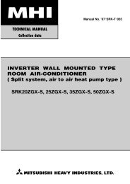
Manual No. ’06 . SRK-T . 060<strong>INVERTER</strong> <strong>WALL</strong> <strong>MOUNTED</strong> <strong>TYPE</strong><strong>ROOM</strong> <strong>AIR</strong>-CONDITIONER( Split system, air to air heat pump type )SRK20ZG-S, SRK25ZG-S, SRK35ZG-S, SRK50ZG-S
CONTENTS1 GENERAL INFORMATION.................................................................... 11.1 Specific features............................................................................ 11.2 How to read the model name ....................................................... 12 SELECTION DATA ................................................................................ 22.1 Specifications ................................................................................ 22.2 Range of usage & limitations ....................................................... 62.3 Exterior dimensions ...................................................................... 62.4 Piping system ................................................................................ 82.5 Selection chart .............................................................................. 93 ELECTRICAL DATA .............................................................................. 103.1 Electrical wiring ............................................................................. 104 OUTLINE OF OPERATION CONTROL BY MICROCOMPUTER ......... 124.1 Operation control function by remote control switch................ 124.2 Unit ON/OFF button....................................................................... 134.3 Power blackout auto restart function .......................................... 134.4 Custom cord switching procedure .............................................. 134.5 Flap and louver control................................................................. 144.6 3D auto operation .......................................................................... 154.7 Timer operation ............................................................................. 164.8 Installation location setting .......................................................... 164.9 Outline of heating operation ........................................................ 174.10 Outline of cooling operation ........................................................ 184.11 Outline of automatic operation .................................................... 184.12 Protective control function........................................................... 195 APPLICATION DATA ............................................................................. 245.1 Selection of location for installation ........................................... 255.2 Installation of indoor unit ............................................................. 265.3 Installation of outdoor unit ........................................................... 295.4 Connection of refrigerant pipings ............................................... 295.5 Test run .......................................................................................... 315.6 Precautions for wireless remote control installation andoperation ........................................................................................ 31
6 MAINTENANCE DATA .......................................................................... 326.1 Troubleshooting procedures for electrical equipment .............. 326.2 Servicing ........................................................................................ 517 INTERFACE KIT (OPTIONAL PARTS).................................................. 527.1 Applicable model........................................................................... 527.2 List of connectable devices ......................................................... 527.3 Exterior dimensions ...................................................................... 527.4 Circuit board component layout .................................................. 527.5 System configuration.................................................................... 537.6 Installation of interface kit ............................................................ 547.7 Wired remote control .................................................................... 597.8 Insatallation of wired remote control .......................................... 607.9 Setting functions using the wired remote control ..................... 617.10 Super link adapter ......................................................................... 657.11 Operation permission/prohibition control .................................. 677.12 External control (remote display) /control of input signal......... 688 REFRIGERANT PIPING INSTALLATION / SERVICING MANUALFOR <strong>AIR</strong> CONDITIONERS USING R410A........................................... 698.1 Outline ............................................................................................ 698.2 Refrigerant piping installation ..................................................... 708.3 Installation, removal and servicing.............................................. 768.4 Refrigerant recovery ..................................................................... 81
1 GENERAL INFORMATION1.1 Specific featuresThe “MITSUBISHI HEAVY INDUSTRIES, LTD” room air-conditioner: SRK series are of split and wall mounted type and the unitconsists of indoor unit and outdoor unit with refrigerant precharged in factory. The indoor unit is composed of room air cooling orheating equipment with operation control switch and the outdoor unit is composed of condensing unit with compressor.(1) Inverter (Frequency converter) for multi-steps power control¡ Heating/CoolingThe rotational speed of a compressor is changed in step in relation to varying load, interlocked with the indoor and outdoor unitfans controlled to change frequency, thus controlling the capacity.¡Allowing quick heating/cooling operation during start-up period. Constant room temperature by fine-tuned control after the unithas stabilized.(2) Fuzzy control¡ Fuzzy control calculates the amount of variation in the difference between the return air temperature and the setting temperaturein compliance with the fuzzy rules in order to control the air capacity and the inverter frequency.(3) Remote control flap & louverThe flap & louver can be automatically controlled by operating wireless remote control.¡Flap swing : The flaps swing up and down successively.¡Louver swing : The louvers swing left and right successively.¡3D auto operation : Fan speed and air flow direction are automatically controlled, allowing the entire room to be efficientlyconditioned.¡Memory flap : Once the flap & louver position is set, the unit memorizes the position and continues to operate at thesame position from the next time.(4) Self diagnosis function¡ We are constantly trying to do better service to our customers by installing such judges that show abnormality of operation asfollows.RUN lightTIMER light1 time flashHeat exchanger sensor error1 time flashOutdoor temperature sensor errorTIMER lightON2 time flashRoom temperature sensor errorRUN lightkeeps flashing2 time flashOutdoor heat exchanger liquidpipe sensor error6 time flashIndoor fan motor error4 time flashDischarge pipe sensor error1 time flashCurrent cut2 time flashTrouble of outdoor unit3 time flashOver currentRUN lightON4 time flash Power transistor error5 time flashOver heat of compressor6 time flashError of signal transmission7 time flashOutdoor fan motor error1.2 How to read the model nameExample : SR K 35 Z G - SRUN light2 time flash2 time flashRotor lockR410A modelsSeries No.Inverter typeProduct capacityWall mounted typeSplit type room air-conditioner- 1 -
2 SELECTION DATA2.1 SpecificationsItemModelSRK20ZG-SCooling capacity (1) W 2000 (500~2800)Heating capacity (1) W 2700 (500~4600)Power source1 Phase, 220-240V, 50HzCooling input kW 0.44 (0.1~0.91)<strong>Ru</strong>nning current (Cooling) A 2.4/2.3/2.2Heating input kW 0.62 (0.09~1.27)<strong>Ru</strong>nning current (Heating) A 3.0/2.9/2.8Inrush current A 3.0/2.9/2.8Operation data (1)ModelCOP Cooling: 4.55 Heating: 4.35SRC20ZG-SSound level Hi 35, Me 29, Lo 21 44CoolingPower level51 58Noise leveldBSound level Hi 35, Me 32, Lo 25 45HeatingPower level 53 59Exterior dimensionsHeight × Width × Depthmm 268 × 790 × 199 540 × 780 × 290Color Fine snow Stucco whiteNet weight kg 8.5 35Refrigerant equipmentCompressor type & Q’ty– RM-B5077MD1 (Rotary type) × 1Motor kW – 0.75Starting method – Line startingHeat exchanger Louver fins & inner grooved tubing Straight fins & inner grooved tubingRefrigerant controlCapillary tubes + Electronic expansion valveRefrigerant (3) kg R410A 0.9 (Pre-Charged up to the piping length of 15m)Refrigerant oil R 0.35 (MA68)Deice controlMicrocomputer controlAir handling equipmentFan type & Q’tyTangential fan × 1 Propeller fan × 1Motor W 38 24Air flow (at High)(Cooling) 7.4 30CMM(Heating)8.5 23Air filter, Q’ty Polypropylene net (washable) × 2 –Shock & vibration absorber – Cushion rubber (for compressor)Electric heater – –Operation controlOperation switchWireless-Remote control –Room temperature control Microcomputer thermostat –Pilot lampRUN (Green), TIMER (Yellow), HI POWER (Green), 3D AUTO (Green)Safety equipmentCompressor overheat protection, Heating overload protection (High pressure control), Overcurrent protection,Frost protection, Serial signal error protection, Indoor fan motor error protection, Cooling overload protectionRefrigerantpipingO.D mm (in) Liquid line: φ6.35 (1/4″) Gas line: φ9.52 (3/8″)Connecting methodFlare connectingAttached length of pipingLiquid line: 0.4 mGas line : 0.33 m–InsulationNecessary (Both sides)Connectable2 m (3 cores with Earth)Size × Core number1.5 mm 2 × 4 cores (Including earth cable)Connecting methodTerminal block (Screw fixing type)Drain hosePower source cordConnection wiringSRK20ZG-S (Indoor unit)SRC20ZG-S (Outdoor unit)(220/230/240V)Accessories (included) Mounting kit, Clean filter (Allergen clear filter x1, Photocatalytic washable deodorizing filter x1)Optional partsInterface kitNotes (1) The data are measured at the following conditions.Item Indoor air temperature Outdoor air temperatureOperation DB WB DB WBStandardsCooling 27ºC 19ºC 35ºC 24ºC ISO-T1, JIS C9612Heating 20ºC – 7ºC 6ºC ISO-T1, JIS C9612The piping length is 7.5m.(2) The operation data are applied to the 220/230/240V districts respectively.(3) The refrigerant quantity to be charged includes the refrigerant in 15 m connecting piping.(Purging is not required even for the short piping.)(4) If the interface kit (SC-BIK-E) (sold separately) is connected to the terminals on the indoor unit’s circuit board, a wired remote control (sold separately)can be connected, a Super Link can be connected, and the unit can be turned on and off from a CNT terminal.- 2 -
ModelSRK25ZG-S (Indoor unit)SRC25ZG-S (Outdoor unit)(220/230/240V)ItemModelSRK25ZG-SCooling capacity (1) W 2500 (500~3000)Heating capacity (1) W 3400 (500~4800)Power source1 Phase, 220-240V, 50HzCooling input kW 0.62 (0.1~0.97)<strong>Ru</strong>nning current (Cooling) A 3.1/3.0/2.9Heating input kW 0.93 (0.09~1.30)<strong>Ru</strong>nning current (Heating) A 4.5/4.3/4.1Inrush current A 4.5/4.3/4.1Operation data (1)COP Cooling: 4.03 Heating: 3.66SRC25ZG-SSound level Hi 36, Me 30, Lo 22 44CoolingPower level52 58Noise leveldBSound level Hi 36, Me 33, Lo 26 47HeatingPower level 54 62Exterior dimensionsHeight × Width × Depthmm 268 × 790 × 199 540 × 780 × 290Color Fine snow Stucco whiteNet weight kg 8.5 35Refrigerant equipmentCompressor type & Q’ty– RM-B5077MD1 (Rotary type) × 1Motor kW – 0.75Starting method – Line startingHeat exchanger Louver fins & inner grooved tubing Straight fins & inner grooved tubingRefrigerant controlCapillary tubes + Electronic expansion valveRefrigerant (3) kg R410A 0.9 (Pre-Charged up to the piping length of 15m)Refrigerant oil R 0.35 (MA68)Deice controlMicrocomputer controlAir handling equipmentFan type & Q’tyTangential fan × 1 Propeller fan × 1Motor W 38 24Air flow (at High)(Cooling) 7.6 30CMM(Heating)8.7 23Air filter, Q’ty Polypropylene net (washable) × 2 –Shock & vibration absorber – Cushion rubber (for compressor)Electric heater – –Operation controlOperation switchWireless-Remote control –Room temperature control Microcomputer thermostat –Pilot lampRUN (Green), TIMER (Yellow), HI POWER (Green), 3D AUTO (Green)Safety equipmentCompressor overheat protection, Heating overload protection (High pressure control), Overcurrent protection,Frost protection, Serial signal error protection, Indoor fan motor error protection, Cooling overload protectionRefrigerantpipingO.D mm (in) Liquid line: φ6.35 (1/4″) Gas line: φ9.52 (3/8″)Connecting methodFlare connectingAttached length of pipingLiquid line: 0.4 mGas line : 0.33 m–InsulationNecessary (Both sides)Connectable2 m (3 cores with Earth)Size × Core number1.5 mm 2 × 4 cores (Including earth cable)Connecting methodTerminal block (Screw fixing type)Drain hosePower source cordConnection wiringAccessories (included) Mounting kit, Clean filter (Allergen clear filter x1, Photocatalytic washable deodorizing filter x1)Optional partsInterface kitNotes (1) The data are measured at the following conditions.Item Indoor air temperature Outdoor air temperatureOperation DB WB DB WBStandardsCooling 27ºC 19ºC 35ºC 24ºC ISO-T1, JIS C9612Heating 20ºC – 7ºC 6ºC ISO-T1, JIS C9612The piping length is 7.5m.(2) The operation data are applied to the 220/230/240V districts respectively.(3) The refrigerant quantity to be charged includes the refrigerant in 15 m connecting piping.(Purging is not required even for the short piping.)(4) If the interface kit (SC-BIK-E) (sold separately) is connected to the terminals on the indoor unit’s circuit board, a wired remote control (sold separately)can be connected, a Super Link can be connected, and the unit can be turned on and off from a CNT terminal.- 3 -
ModelSRK35ZG-S (Indoor unit)SRC35ZG-S (Outdoor unit)(220/230/240V)ItemModelSRK35ZG-SCooling capacity (1) W 3500 (500~3900)Heating capacity (1) W 4200 (500~5100)Power source1 Phase, 220-240V, 50HzCooling input kW 1.05 (0.1~1.22)<strong>Ru</strong>nning current (Cooling) A 4.9/4.7/4.5Heating input kW 1.14 (0.09~1.32)<strong>Ru</strong>nning current (Heating) A 5.3/5.1/4.9Inrush current A 5.3/5.1/4.9Operation data (1)COP Cooling: 3.33 Heating: 3.68SRC35ZG-SSound level Hi 40, Me 32, Lo 23 48CoolingPower level56 62Noise leveldBSound level Hi 41, Me 36, Lo 27 50HeatingPower level 59 64Exterior dimensionsHeight × Width × Depthmm 268 × 790 × 199 540 × 780 × 290Color Fine snow Stucco whiteNet weight kg 8.5 38Refrigerant equipmentCompressor type & Q’ty– RM-B5077MD1 [Rotary type] × 1Motor kW – 0.90Starting method – Line startingHeat exchanger Louver fins & inner grooved tubing Straight fins & inner grooved tubingRefrigerant controlCapillary tubes + Electronic expansion valveRefrigerant (3) kg R410A 1.1 (Pre-Charged up to the piping length of 15m)Refrigerant oil R 0.35 (MA68)Deice controlMicrocomputer controlAir handling equipmentFan type & Q’tyTangential fan × 1 Propeller fan × 1Motor W 38 24Air flow (at High)(Cooling) 8.5 30CMM(Heating)10.8 33Air filter, Q’ty Polypropylene net (washable) × 2 –Shock & vibration absorber – Cushion rubber (for compressor)Electric heater – –Operation controlOperation switchWireless-Remote control –Room temperature control Microcomputer thermostat –Pilot lampRUN (Green), TIMER (Yellow), HI POWER (Green), 3D AUTO (Green)Safety equipmentCompressor overheat protection, Heating overload protection (High pressure control), Overcurrent protection,Frost protection, Serial signal error protection, Indoor fan motor error protection, Cooling overload protectionRefrigerantpipingO.D mm (in) Liquid line: φ6.35 (1/4″) Gas line: φ9.52 (3/8″)Connecting methodFlare connectingAttached length of pipingLiquid line: 0.4 mGas line : 0.33 m–InsulationNecessary (Both sides)Connectable2 m (3 cores with Earth)Size × Core number1.5 mm 2 × 4 cores (Including earth cable)Connecting methodTerminal block (Screw fixing type)Drain hosePower source cordConnection wiringAccessories (included) Mounting kit, Clean filter (Allergen clear filter x1, Photocatalytic washable deodorizing filter x1)Optional partsInterface kitNotes (1) The data are measured at the following conditions.Item Indoor air temperature Outdoor air temperatureOperation DB WB DB WBStandardsCooling 27ºC 19ºC 35ºC 24ºC ISO-T1, JIS C9612Heating 20ºC – 7ºC 6ºC ISO-T1, JIS C9612The piping length is 7.5m.(2) The operation data are applied to the 220/230/240V districts respectively.(3) The refrigerant quantity to be charged includes the refrigerant in 15 m connecting piping.(Purging is not required even for the short piping.)(4) If the interface kit (SC-BIK-E) (sold separately) is connected to the terminals on the indoor unit’s circuit board, a wired remote control (soldseparately) can be connected, a Super Link can be connected, and the unit can be turned on and off from a CNT terminal.- 4 -
ModelSRK50ZG-S (Indoor unit)SRC50ZG-S (Outdoor unit)(220/230/240V)ItemModelSRK50ZG-SCooling capacity (1) W 5000 (600~5300)Heating capacity (1) W 5800 (600~7900)Power source1 Phase, 220-240V, 50HzCooling input kW 1.66 (0.12~2.1)<strong>Ru</strong>nning current (Cooling) A 7.6/7.3/7.0Heating input kW 1.70 (0.11~2.71)<strong>Ru</strong>nning current (Heating) A 7.9/7.5/7.2Inrush current A 7.9/7.5/7.2Operation data (1)COP Cooling: 3.01 Heating: 3.41SRC50ZG-SSound level Hi 47, Me 42, Lo 26 48CoolingPower level61 61Noise leveldBSound level Hi 48, Me 40, Lo 34 50HeatingPower level 62 64Exterior dimensionsHeight × Width × Depthmm 268 × 790 × 199 640 × 850 × 290Color Fine snow Stucco whiteNet weight kg 8.5 43Refrigerant equipmentCompressor type & Q’ty– 5CS102XFA [Scroll type] × 1Motor kW – 1.5Starting method – Line startingHeat exchanger Slit fins + Louver fins & inner grooved tubing Straight fins & inner grooved tubingRefrigerant controlCapillary tubes + Electronic expansion valveRefrigerant (3) kg R410A 1.35 (Pre-Charged up to the piping length of 15m)Refrigerant oil R 0.36 (RB68A)Deice controlMicrocomputer controlAir handling equipmentFan type & Q’tyTangential fan × 1 Propeller fan × 1Motor W 38 34Air flow (at High)(Cooling) 11.5 42CMM(Heating)13.0 42Air filter, Q’ty Polypropylene net (washable) × 2 –Shock & vibration absorber – Cushion rubber (for compressor)Electric heater – –Operation controlOperation switchWireless-Remote control –Room temperature control Microcomputer thermostat –Pilot lampRUN (Green), TIMER (Yellow), HI POWER (Green), 3D AUTO (Green)Safety equipmentCompressor overheat protection, Heating overload protection (High pressure control), Overcurrent protection,Frost protection, Serial signal error protection, Indoor fan motor error protection, Cooling overload protectionRefrigerantpipingO.D mm (in) Liquid line: φ6.35 (1/4″) Gas line: φ12.7 (1/2″)Connecting methodFlare connectingAttached length of pipingLiquid line: 0.4 mGas line : 0.33 m–InsulationNecessary (Both sides)Connectable2 m (3 cores with Earth)Size × Core number1.5 mm 2 × 4 cores (Including earth cable)Connecting methodTerminal block (Screw fixing type)Drain hosePower source cordConnection wiringAccessories (included) Mounting kit, Clean filter (Allergen clear filter x1, Photocatalytic washable deodorizing filter x1)Optional partsInterface kitNotes (1) The data are measured at the following conditions.Item Indoor air temperature Outdoor air temperatureOperation DB WB DB WBStandardsCooling 27ºC 19ºC 35ºC 24ºC ISO-T1, JIS C9612Heating 20ºC – 7ºC 6ºC ISO-T1, JIS C9612The piping length is 7.5m.(2) The operation data are applied to the 220/230/240V districts respectively.(3) The refrigerant quantity to be charged includes the refrigerant in 15 m connecting piping.(Purging is not required even for the short piping.)If the piping length is longer, when it is 15 to 25m, add 20 g refrigerant per meter.(4) If the interface kit (SC-BIK-E) (sold separately) is connected to the terminals on the indoor unit’s circuit board, a wired remote control (soldseparately) can be connected, a Super Link can be connected, and the unit can be turned on and off from a CNT terminal.- 5 -
2.2 Range of usage & limitationsItemIndoor return air temperature(Upper, lower limits)Outdoor air temperature(Upper, lower limits)ModelsSRK20ZG-S, 25ZG-S, 35ZG-SSRK50ZG-SCooling operation : Approximately 18 to 32˚CHeating operation : Approximately 15 to 30˚CCooling operation : Approximately -15 to 46˚CHeating operation : Approximately -15 to 21˚CRefrigerant line (one way) lengthVertical height difference betweenoutdoor unit and indoor unitMax. 15mMax. 10m (Outdoor unit is higher)Max. 10m (Outdoor unit is lower)Max. 25mMax. 15m (Outdoor unit is higher)Max. 15m (Outdoor unit is lower)Power source voltage Rating ± 10%Voltage at startingFrequency of ON-OFF cycleON and OFF intervalMax. 4 times/h(Inching prevention 10 minutes)Min. 85% of ratingMax. 3 minutesMax. 7 times/h(Inching prevention 5 minutes)2.3 Exterior dimensions(1) Indoor unitModels SRK20ZG-S, 25ZG-S, 35ZG-S, 50ZG-SA→790199 3Unit: mmPiping hole right(left)960268Terminal block45138206.5102.5450585450202133.5102.539.320044.5 43.253.5Pipng for Gas53.520, 25, 35 : ø9.52( 50 : ø12.7)380.644.5252.2 7.58.378817.5 6060 274545Pipng for Liquid 448.6 (ø6.35)Drain hose 520 (ø16)VIEW APiping hole (ø65)Piping hole (ø65)- 6 -
(2) Outdoor unitModels SRC20ZG-S, 25ZG-S, 35ZG-SUnit: mm43.1313.1Drain holes (ø20)501223.5104.9349.5439.151078014165.1 18.961.92-16×12138.440˚Model SRC50ZG-S29049.6 43.5286.4 Drain holes5012476203.1 510 136.9314 122-16×12328850Terminal block124 34.6Groundterminal42.7100.320˚20˚Service valve (Liquid)ø6.35 (1/4'')Service valve (Gas)ø12.7 (1/2'')15111.499.4290312.5350Terminal block33.5Service valve (Liquid)Flare connection ø6.35 (1/4'')42.554040˚1495.9Service valve (Gas)Flare connection ø9.52 (3/8'')14640- 7 -
2.4 Piping systemModels SRK20ZG-S, 25ZG-S, 35ZG-SHumiditysensor(35 type only)Indoor unitFlare connectionPiping(Gas)ø9.52Outdoor unitService valve(Gas)Check jointMufflerCooling cycleHeating cycleOutdoor airtemp. sensor4 way valveAccumulatorRoom temp.sensorHeatexchangerHeatexchangersensorDischarge pipetemp. sensorCompressorHeatexchangerHeat exchangersensorPiping(Liquid)ø6.35Service valve (Liquid)Capillary tubeCapillary tubeFlare connetionStrainerElectronicexpansion valveModel SRK50ZG-SHumiditysensorIndoor unitFlare connectionPiping(Gas)ø12.7Outdoor unitService valve(Gas)Check jointMufflerCooling cycleHeating cycleOutdoor airtemp. sensor4 way valveStrainerRoom temp.sensorHeatexchangerHeatexchangersensorDischarge pipetemp. sensorCompressorHeatexchangerHeat exchangersensorPiping(Liquid)ø6.35Service valve (Liquid)Capillary tubeCapillary tubeFlare connectionStrainerElectronicexpansion valve- 8 -
2.5 Selection chartCorrect the cooling and heating capacity in accordance with the conditions as follows. The net cooling and heating capacity can beobtained in the following way.Net capacity = Capacity shown on specification ✕ Correction factors as follows.(1) Coefficient of cooling and heating capacity in relation to temperatures1.3Coefficient of cooling &Heating capacity inrelation to temperature1.21.11.00.90.8CoolingHeating0.70.6Applicable rangeCooling operationOutdoor air D.B.temperature˚CD. B.4640353025202624Heating operationIndoor air D.B.temperature˚CD. B.0-5-10-152725201510Depends on installed situation14 16 18 20 22Indoor air W.B. temperature ˚C W.B.ISO-T1 Standard Condition-15 -10 -5 0 5 10 15ISO-T1 Standard ConditionOutdoor air W.B. temperature ˚C W.B.(2) Correction of cooling and heating capacity in relation to one way length of refrigerant pipingIt is necessary to correct the cooling and heating capacity in relation to the one way piping length between the indoor and outdoorunits.Piping length [m]CoolingHeating71.01.0100.991.0150.9751.0200.9651.0250.951.0(3) Correction relative to frosting on outdoor heat exchanger during heatingIn additions to the foregoing corrections (1), (2) the heating capacity needs to be adjusted also with respect to the frosting on theoutdoor heat exchanger.Air inlet temperature ofoutdoor unit in ˚C WB-10-9-7-5-3-1135Adjustment coefficient0.950.940.930.910.880.860.870.921.00How to obtain the cooling and heating capacityExample : The net cooling capacity of the model SRK20ZG-S with the piping length of 15m, indoor wet-bulb temperature at 19.0˚Cand outdoor dry-bulb temperature 35˚C is Net cooling capacity = 2000 ✕ 0.975 ✕ 1.0 = 1950 WSRK20ZG-SLength 15mFactor by airtemperatures- 9 -
- 10 -POWER SOURCE1 Phase220/230/240V 50HzFMISMLM1LM2BRLBY/GNCONTROLBOX555Color symbolBKBLBRLBRDWHYY/GHEATEXCHANGERBLYWHBKRDBlackBlueBrownLight blueRedWhiteYellowYellow/Green65431CNUCNMCNXCNYWHNCNEZNR8DISPLAYBRWIRELESSR-AMPBACK UP SW52C-4 52C-3U52CF250V 3.15ABKCNG2 2RDBOARD52CPRINTED CIRCUITCNFTh1 Th2 Th3(35 <strong>TYPE</strong> ONLY)JY/GN2GIndoor unitY/GNRDWHBK32/N1TBTB32/N1Outdoor unitRDWHBKLEEV20SFMOTh4Th5Th6F250V 15AGGCNECNBCNACNDDSR.IN S.IN C-2~~- ++++PRINTED CIRCUIT BOARDModels SRK20ZG-S, 25ZG-S, 35ZG-S3.1 Electrical wiring3 ELECTRICAL DATAMeaning of marksSymbol Parts name Symbol Parts name Symbol Parts nameCMFFMIFMOSMLM1LM2Compressor motorFuseFan motor(Indoor)Fan motor(Outdoor)Flap motorLouver motor(L)Louver motor(R)Th1Th2Th3Th4Th5Th6ZNRRoom temp.sensorHeat exch.sensor(Indoor unit)Humidity sensorHeat exch.sensor(Outdoor unit)Outdoor air temp.sensorDischarge pipe temp.sensorVaristor20SEEVDSLTB4 way valve(coil)Electronic expansion valveDiode stackInductorTerminal blockCMRDWHBKUVWNPPOWERTRANSISTOR
POWER SOURCE1 Phase220/230/240V 50HzFMISMLM1BRLBY/GNCONTROLBOX55HEATEXCHANGERBLYWHBKRD65431CNUCNMCNXWHNBRBK52C-4 52C-352CF250V 3.15AZNRURDJPRINTED CIRCUITBOARDY/GNG52CIndoor unitY/GNRDWHBK32/N1TBFMO20STB32/N1Outdoor unitRDWHBKF250V 15ACNTCNBPWB1(MAIN)DC-PDC-NRDBKCNGN_1PWB3(CAPACITOR)Y/GP_1G3 L-1 N-1 CNO.1AC.NAC.NBLBLAC.LGRGRAC.LModel SRK50ZG-S- 11 -LM25CNYCNECNGCNFTh4Th5Th6CNDBKRDP_1N_1Color symbolBKBLBRGRLBORRDWHYY/GBlackBlueBrownGrayLight blueOrangeRedWhiteYellowYellow/Green8DISPLAYWIRELESSR-AMPBACK UP SW2 2 2Th1 Th2 Th3EEVCNJCNICNGCNHCNGCNHW VPWB2(POWER)URDWHBKAF_L2 ORORAF_L1Meaning of marksSymbol Parts name Symbol Parts name Symbol Parts nameCMFFMIFMOSMLM1LM2Compressor motorFuseFan motor(Indoor)Fan motor(Outdoor)Flap motorLouver motor(L)Louver motor(R)Th1Th2Th3Th4Th5Th6ZNRRoom temp.sensorHeat exch.sensor(Indoor unit)Humidity sensorHeat exch.sensor(Outdoor unit)Outdoor air temp.sensorDischarge pipe temp.sensorVaristor20SEEVDSLTB4 way valve(coil)Electronic expansion valveDiode stackInductorTerminal blockRDWHBKCMORORL
4 OUTLINE OF OPERATION CONTROL BY MICROCOMPUTER4.1 Operation control function by remote control switchRemote controlModels All modelsS Operation sectionFAN SPEED buttonEach time the button is pushed, theindicator is switched over in turn.OPERATION MODE select buttonEach time the button pushed, theindicator is switched over in turn.HI POWER/ECONO buttonThis button changes the HIGH POWER/ECONOMY mode.TEMPERATURE buttonThis button sets the room temperature.(This button changes the present time andTIMER time.)ON TIMER buttonThis button selects ON TIMER operation.ON/OFF (luminous) buttonPress for starting operation, press againfor stopping.<strong>AIR</strong> FLOW (UP/DOWN) buttonThis button changes the air flow (up/down) mode.<strong>AIR</strong> FLOW (LEFT/RIGHT) buttonThis button changes the air flow (left/right) mode.3D AUTO buttonThis button sets 3D AUTO operation.SLEEP buttonThis button selects to SLEEP operation.OFF TIMER buttonThis button selects OFF TIMER operation.CLEAN switchThis switch changes the CLEAN mode.CANCEL buttonThis button cancels the ON timer, OFFtimer, and SLEEP operation.• The above illustration shows all controls, but in practiceonly the relevant parts are shown.RESET switchSwitch for resetting microcomputer andsetting time.ALLERGEN CLEAR buttonThis button selects ALLERGEN CLEARoperation.Unit indication sectionModels All modelsTIMER light (yellow)Illuminates during TIMER operation.HI POWER light (green)Illuminates during HIGH POWER operation.RUN (HOT KEEP) light (green)3D AUTO light (green)• Illuminates during operation and CLEANoperation.• Blinks at air flow stop due to the ‘HOT KEEP’.Illuminates during 3D AUTO operation.ON1.5 sec.RUNTIMERON / OFFHI POWER3D AUTOOFF0.5 sec.Unit ON/OFF buttonIn emergencies, this button can be used for turning on/off the unitwhen remote control is not available.Remote control signal receiver- 12 -
4.2 Unit ON/OFF buttonWhen the remote control batteries become weak, or if the remote control is lost or malfunctioning, this button may be used to turn theunit on and off.(1) OperationPush the button once to place the unit in the automatic mode. Push it once more to turn the unit off.(2) Details of operationThe unit will go into the automatic mode in which it automatically determines, from room temperature (as detected by sensor),whether to go into the cooling, thermal dry or heating modes.Function Room temperatureOperation modesettingFan speed Flap Timer switchCooling About 24ºCThermal dry About 24ºC Auto Auto ContinuousHeating About 26ºCUnit ON/OFF button4.3 Power blackout auto restart function(1) Power blackout auto restart function is a function that records the operational status of the air-conditioner immediately prior to itbeing switched off by a power cut, and then automatically resumes operations at that point after the power has been restored.(2) The following settings will be cancelled:Jumper wire (J12)(a) Timer settings(b) High-power operationsNotes (1) The power blackout auto restart function is set at on when the air-conditioner is shipped from thefactory. Consult with your dealer if this function needs to be switched off.(2) When power failure ocurrs, the timer setting is cancelled. Once power is resumed, reset the timer.(3) If the jumper wire (J12) “AUTO RESTART” is cut, auto restart is disabled. (See the diagram at right)4.4 Custom cord switching procedureJumper wire (J13)If two wireless remote controls are installed in one room, in order to prevent wrong operationdue to mixed signals, please modify the printed circuit board in the indoor unit’s control boxand the remote control using the following procedure. Be sure to modify both boards. If onlyone board is modified, receiving (and operation) cannot be done.(1) Modifying the indoor unit’s printed circuit boardTake out the printed circuit board from the control box and cut off jumper wire (J13)using wire cutters.After cutting of the jumper wire, take measures to prevent contact with the other the leadwires, etc.(2) Modifying the wireless remote control(a) Remove the battery.Cut(b) Cut the jumper wire shown in the figure at right.- 13 -
4.5 Flap and louver controlControl the flap and louver by <strong>AIR</strong>FLOW (UP/DOWN) and (LEFT/RIGHT) button on the wireless remote control.(1) FlapEach time when you press the <strong>AIR</strong>FLOW (UP/DOWN) button the mode changes as follows.(Flap stopped)(Swing)• Angle of Flap from HorizontalRemote controldisplayCOOL , DRYApprox. 10˚Approx. 20˚Approx. 30˚Approx. 45˚Approx. 60˚HEATApprox. 20˚Approx. 35˚Approx. 50˚Approx. 60˚Approx. 70˚(2) LouverEach time when you press the <strong>AIR</strong>FLOW (LEFT/RIGHT) button the mode changes as follows.(Louver stopped)• Angle of Louver(Swing) (Spot) (Wide)Remote controldisplayCenter installationRight end installationLeft end installationLeft Approx. 45˚ Left Approx. 20˚Left Approx. 45˚ Left Approx. 30˚Center Right Approx. 20˚ Right Approx. 45˚Left Approx. 20˚ Center Right Approx. 20˚Left Approx. 20˚ Center Right Approx. 20˚ Right Approx. 30˚ Right Approx. 45˚(3) Swing(a) Swing flapFlap moves in upward and downwarddirections continuously.(b)Swing louverLouver moves in left and right directions continuously.S In HEAT operation S In COOL, DRY operation S In HEAT operation S In COOL, DRY operationApprox.10˚Approx. 30˚Approx. 30˚Approx. 70˚(4) Memory flap (Flap or Louver stopped)When you press the <strong>AIR</strong>FLOW (UP/DOWN or LEFT/RIGHT) button once while the flap or louver is operating, it stops swingingat an angle. Since this angle is memorized in the microcomputer, the flap or louver will automatically be set at this angle when thenext operation is started.(5) When not operatingThe flap returns to the position of air flow directly below, when operation has stopped.- 14 -
4.6 3D auto operationControl the flap and louver by 3D AUTO button on the wireless remote control.Air flow selection and air flow direction are automatically controlled, allowing the entire room to efficiently conditioned.(1) During Cooling and Heating (Including auto cooling and heating)(a) Air flow selection is determined according to room temperature and setting temperature.Air flow selectionOperation modeAUTO HI MED LORoom temp. – Setting temp. >5˚C Room temp. – Setting temp. ≤_ 5˚CAt coolingHIGH POWERAUTOHI MED LOSetting temp. – Room temp. >5˚C Setting temp. – Room temp. ≤_ 5˚CAt heatingHIGH POWERAUTO(b)Air flow direction is controlled according to the room temperature and setting temperature.1) When 3D auto operation startsFlapLouverCoolingWide (fixed)Up/down SwingHeatingCenter (fixed)2) When Room temp. – Setting temp. is ≤_ 5ºC during cooling and when Setting temp. – Room temp. is ≤_ 5ºC duringheating, the system switches to the following air flow direction control. After the louver swings left and right symmetricallyfor 3 cycles, control is switched to the control in 3).FlapLouverCoolingHeatingHorizontal blowing (Fixed) Slant forwardl blowing (Fixed)Left/right Swing3) After the flap swings for 5 cycles, control is switched to the control in 4).FlapLouverCoolingUp/down SwingCenter (Fixed)Heating4) For 5 minutes, the following air flow direction control is carried out.FlapLouverCoolingHeatingHorizontal blowing (Fixed) Slant forwardl blowing (Fixed)Wide (Fixed)5) After 5 minutes have passed, the air flow direction is determined according to the room temperature and settingtemperature.Operation modeAt coolingAt heatingAir flow direction contorolRoom temp. – Setting temp. ≤_ 2˚CThe control in 4) continues.2˚C < Room temp. – Setting temp. ≤_ 5˚CControl returns to the control in 2).Room temp. – Setting temp. > 5˚CControl returns to the control in 1).Setting temp. – Room temp. ≤_ 2˚C 2˚C < Setting temp. – Room temp. ≤_ 5˚C Setting temp. – Room temp. > 5˚CThe control in 4) continues. Control returns to the control in 2). Control returns to the control in 1).(2) During DRY Operation (including auto DRY operation)Air flow selectionFlapLouverAccording to DRY operation.Horizontal blowing (Fixed)Wide (Fixed)- 15 -
4.7 Timer operation(1) Comfortable timer setting (ON timer)If the timer is set at ON when the operation select switch is set at the cooling or heating, or the cooling or heating in auto modeoperation is selected, the comfortable timer starts and determines the starting time of next operation based on the initial value of 15minutes and the relationship between the room temperature at the setting time (temperature of room temperature sensor) and thesetting temperature.(2) Sleep timer operationPressing the SLEEP button causes the temperature to be controlled as shown in the following chart with respect to the set temperature.(3) OFF timer operationThe Off timer can be set at a specific time (in 10-minute units) within a 24-hour period.4.8 Installation location settingWhen the indoor unit is installed at the end of a room, control the air flow direction so that it is not toward the side walls. If you set theremote control’s installation position, keep it so that the air flow is within the range shown in the following figure.(1) Setting1 If the air conditioning unit is running, press the ON/OFF button to stop.The installation location setting cannot be made while the unit is running.2 Press the <strong>AIR</strong> FLOW (UP/DOWN) button and the<strong>AIR</strong>FLOW (LEFT/RIGHT) button together for 5 secondsor more.The installation location display illuminates.3 Setting the air-conditioning installation location.Press the <strong>AIR</strong> FLOW (LEFT/RIGHT) button and adjust to the desired1, 4location.2Each time the <strong>AIR</strong> FLOW (LEFT/RIGHT) button is pressed, the3indicator is switched in the order of:(Center Installation) (Right End Installation) (Left End Installation)4 Press the ON/OFF button.The air-conditioner's installation location is set.Press within 60 seconds of setting the installation location (while theinstallation location setting display illuminates).Airflow range Airflow range Airflow range(Left End Installation) (Center Installation) (Right End Installation)- 16 -
4.9 Outline of heating operation(1) Operation of major functional components in heating modeCompressorIndoor fan motorOutdoor fan motor4-way valveHeatingThermostat ON Thermostat OFF Defrost FailureON OFF OFFOFFON ON(HOT KEEP) OFFONOFF(few minutes ON)OFFON ON OFFOFFOFFOFF(3 minutes ON)(2) Details of control at each operation mode (pattern)(a) Fuzzy operationDeviation between the room temperature setting correction temperature and the suction air temperature is calculated inaccordance with the fuzzy rule, and used for control of the air capacity and the inverter speed.(b)Fan speedAutoHIMEDLOModelSRK20ZG-SSRK25ZG-S SRK35ZG-S SRK50ZG-S30~100rps 30~102rps 15~122rps30~100rps 30~102rps 15~122rps30~70rps 30~72rps 30~84rps 15~84rps30~44rps 30~54rps 30~62rps 15~66rpsWhen the defrosting, protection device, etc. is actuated, operation is performed in the corresponding mode.Hot keep operationIf the hot keep operation is selected during the heating operation, the indoor blower is controlled based on the temperature ofthe indoor unit heat exchanger (detected with Th2, indoor unit heat exchanger sensor) to prevent blowing of cool wind.(3) Defrosting operation(a) Starting conditions (Defrosting operation can be started only when all of the following conditions are met.)1 After start of heating operationWhen it elapsed 45 minutes (35, 50 type : 35 minutes). (Accumulated compressor operation time)2 After end of defrosting operationWhen it elapsed 45 minutes(35, 50 type : 35 minutes). (Accumulated compressor operation time)3 Outdoor unit heat exchanger sensor (Th4) temperatureWhen the temperature has been below –5ºC for 3 minutes continuously.4 The difference between the outdoor air sensor temperature and the outdoor unit heat exchanger sensor temperature¡ The outdoor air temperature ≥_ -17°C : 7°C (35type : 5°C, 50type : 4°C) on higher¡ The outdoor air temperature < -17°C : -5°C or higher5 During continuous compressor operationIn addition, when the speed command from the indoor controller of the indoor unit during heating operation has counted0 rps 10 times or more and all conditions of 1, 2, 3 and 5 above and the outdoor air temperature is 3°C or less aresatisfied (note that when the temperature for Th4 is -5°C or less: 62 rps or more, -4°C or less: less than 62 rps), defrostoperation is started.(b) Ending conditions (Operation returns to the heating cycle when either one of the following is met.)1 Outdoor heat exchanger sensor (Th4) temperature: 13ºC or higher2 Continued operation time of defrosting → For more than 10 min.- 17 -
4.10 Outline of cooling operation(1) Operation of major functional components in Cooling modeCompressorIndoor fan motorOutdoor fan motor4-way valveCoolingThermostat ON Thermostat OFF FailureON OFF OFFON ON ONONOFF(few minutes ON)OFF(few minutes ON)OFF OFF OFF(2) Detail of control in each mode (Pattern)(a)Fuzzy operationDuring the fuzzy operation, the air flow and the inverter speed are controlled by calculating the difference between the roomtemperature setting correction temperature and the suction air temperature.Fan speedAutoHIMEDLOModelSRK20ZG-SSRK25ZG-S SRK35ZG-S SRK50ZG-S20~64rps 20~68rps 20~98rps15~100rps20~64rps20~68rps20~98rps15~100rps20~48rps 20~52rps 20~74rps 15~62rps20~32rps 20~38rps 20~46rps 15~30rps4.11 Outline of automatic operation(1) Determination of operation modeThe unit checks the room temperature and the outdoor air temperature, determines the operation mode, and then begins in theautomatic operation.27.525.5Room temperature (˚C)19.5DehumidifyingCoolingHeating18 30Outdoor temperature (˚C)(2) The unit checks the temperature every hour after the start of operation and, if the result of check is not same as the previousoperation mode, changes the operation mode.(3) When the unit is started again within one hour after the stop of automatic operation or when the automatic operation is selectedduring heating, cooling or dehumidifying operation, the unit is operated in the previous operation mode.(4) Setting temperature can be adjusted within the following range. There is the relationship as shown below between the signals of thewireless remote control and the setting temperature.SettingtemperatureSignals of wireless remote control (Display)–6 –5 –4 –3 –2 –1 ±0 +1 +2 +3 +4 +5 +6Cooling 18 19 20 21 22 23 24 25 26 27 28 29 30Dehumidifying 18 19 20 21 22 23 24 25 26 27 28 29 30Heating 20 21 22 23 24 25 26 27 28 29 30 31 32- 18 -
4.12 Protective control function(1) Frost prevention for indoor heat exchanger (During cooling or dehumidifying)(a) Operating conditions1) Indoor heat exchanger temperature (detected with Th2) is lower than 5ºC.2) 10 minutes after reaching the inverter command speed except 0 rps.(b) Detail of anti-frost operation(c)Item5°C or lower 2.5°C or lower20, 25 type : 44 rpsUpper limit speed 35 type : 70 rps 0rps50 type : 76 rpsIndoor fanOutdoor fan4-way valveIndoor heat exchangertemperatureDepends on operation modeDepends on operation modeOFFProtects the fan tap just beforefrost prevention controlDepends on stop modeInvertercommandspeedUpperlimitspeed2.5 5 8Indoor heat exchangertemperature (°C)Reset conditions: The indoor heat exchanger temperature (Th2) is 8ºC or higher after 5 minutes of operation followingcontrol of the inverter command speed upper limit.0 rps(2) Cooling overload protective control(a) Operating conditions: When the outdoor unit is operating with the outdoor unit speed of other than 0 rps, and when theoutdoor air temperature sensor (Th5) becomes 41ºC or over for 30 seconds continuously.(b) Detail of operation1) Outdoor fan is stepped up by 3 speed step. (Upper limit speed is 7th speed.)2) The lower limit of control speed is set to 30 rps and even if the calculated result becomes lower than that after fuzzycalculation, the speed is kept to 30 rps. However, when the thermo becomes OFF, the speed is reduced to 0 rps.(c) Reset conditions: When either of the following condition is satisfied.1 When the outdoor air temperature becomes 40ºC or less.2 When the inverter command speed is 0rps.(3) Cooling low outdoor temperature protective control◆ < I >(a) Operating conditions: When the outdoor air temperature sensor (Th5) is 22ºC or lower continues for 30 seconds whileoutdoor speed is other than 0rps.(b) Detail of operation: After the outdoor fan operates at A speed for 60 seconds; the corresponding outdoor heatexchanger temperature shall implement the following controls.¡ Value of AOutdoor fanOutdoor temperature > 10˚COutdoor temperature ≤_ 10˚C2nd speed1st speed(c)1 Outdoor heat exchanger temperature < = 21ºCAfter the outdoor fan speed drops (down) to one speed for 60 seconds; if the outdoor heat exchanger temperature islower than 21°C, gradually reduce the outdoor fan speed by 1 speed. (Lower limit speed is 1st speed)2 21ºC < Outdoor heat exchanger temperature < = 38ºCAfter the outdoor fan speed maintains at A speed for 20 seconds; if the outdoor heat exchanger temperature is 21°C~38°C, maintain outdoor fan speed.3 Outdoor heat exchanger tempeature > 38ºCAfter the outdoor fan speed rises (up) to 1 speed for 60 seconds; if the outdoor heat exchanger temperature ishigher than 38°C, gradually increase outdoor fan speed by 1 speed. (Upper limit speed is 3rd speed)Reset conditions: When the either of the following conditions is satisfied1 When the outdoor air temperature sensor (Th5) becomes 25ºC or higher.2 When the inverter command speed is 0rps.- 19 -
◆ < II >(a) Operating conditions: When the outdoor air temperature sensor (Th5) is 22ºC or lower continues for 30 seconds whileoutdoor speed is other than 0rps.(b) Detail of operation:1 The lower limit of inverter command speed is set to C(D)rps and even if the speed becomes lower than C(D)rps, thespeed is kept to C(D)rps. However, when the thermo becomes OFF, the speed is reduced to 0rps.2 The upper limit of control speed is set to A(B)rps and even if the calculated result becomes higher than that after fuzzycalculation, the speed is kept to A(B)rps.ONUpper limit ArpsLower limit CrpsONUpper limit BrpsLower limit Drps¡ Values of A, B, C, DOFFUpper limit Lower limitA B C D0 322 25Outdoor air temp.(°C)20, 25, 35 type50 type4060 30 3050 60 44 30(c)Reset conditions: When the either of the following condition is satisfied1 When the outdoor air temperature sensor (Th5) becomes 25ºC or higher.2 When the inverter command speed is 0rps.(4) High pressure control(a) Purpose: Prevents anomalous high pressure operation during heating.(b) Detector: Indoor unit heat exchanger sensor (Th2)(c) Detail of operation:(Example) FuzzyAfter lapse of 20 sec. or over (3)4rps (1) 8rps (2) 8rps (2)After lapse of 20 sec. or over (3)After lapse of 20 sec. or over (3)lower limitspeed 20(35) rps4rps (1)0rpsA B C DIndoor unit heat exchanger temperature(˚C)Notes (1) When the indoor unit heat exchanger temperature is in the range of B~C ºC, the speed is reduced by 4 rps at each 20 seconds.(2) When the indoor unit heat exchanger temperature is in the range of C~D ºC, the speed is reduced by 8 rps at each 20 seconds. When the temperature is DºC or over for 1 minute continuously, the inverter is stopped.(3) When the indoor unit heat exchanger temperature is in the range of A~B ºC, if the inverter command speed is been maintained and the operation hascontinued for more than 20 seconds at the same speed, it returns to the normal heating operation.(4) Indoor blower retains the fan tap when it enters in the high pressure control. Outdoor blower is operated in accordance with the speed.¡ Temperature listA B C DRPSmin < 40(88) 48 (48.5) 53 (55) 55 (58) 58 (61)40(88) < = RPSmin < 50(108) 48 (44) 53 (50.5) 55 (53) 58 (56.5)50(108) < = RPSmin 48.5 (39) 56 (45.5) 58 (48) 61 (51.5)Notes (1) RPSmin: The lower one between the outdoor unit speed and the command speedNote (2) Values in ( ) are for Type 50.Unit : ºC- 20 -
(5) Heating overload protective control(a) Operating conditions: When the unit is operating with the outdoor unit speed other than 0 rps or when the outdoor airtemperature sensor (Th5) rose beyond 22ºC for 30 seconds continuously.(b) Detail of operation:1 Taking the upper limit of control speed range at 60 rps, if the output speed obtained with the fuzzy calculation exceeds theupper limit, the upper limit value is maintained.2 The lower limit of control speed is set to 40(35) rps and even if the calculated result becomes lower than that after fuzzycalculation, the speed is kept to 40(35) rps. However, when the thermo becomes OFF, the speed is reduced to 0 prs.3 Inching prevention control is activated and inching prevention control is carried out with the minimum speed set at 40(35) rps.4 The outdoor fan is set on 2nd speed.(c) Reset conditions: When the outdoor air temperature drops below 21ºC.Note (1) Values in ( ) are for Type 50.(6) Heating low outdoor temperature protective control◆ (a) Operating conditions: When the outdoor air temperature sensor (Th5) is 4ºC or lower continues for 5 minutes while theoutdoor speed is other than 0 rps.(b) Detail of operation:1 When the command speed is less than 40(22) rps, the command speed is forcibly set at 40(22) rps. However, when thethermo becomes OFF, the speed is reduced 0 rps.2 Inching prevention control is activated and inching prevention control is carried out with the minimum speed set at 40(22) rps.(c) Reset conditions: When the either of the following condition is satisfied.1 When the outdoor air temperature sensor (Th5) becomes 6ºC or higher.2 When the inverter command speed is 0 rps.◆ (a) Operating conditions: When the outdoor air temperature sensor (Th5) is 0ºC or lower continuously for 30 seconds whilethe outdoor speed is other than 0 rps.(b) Detail of operation: The outdoor fan motor speed is stepped up by 1(2) speed step. (Upper limit 7th speed)(c) Reset conditions: When the either of the following condition is satisfied.1 When the outdoor air temperature sensor (Th5) becomes 2ºC or higher.2 When the inverter command speed is 0 rps.◆ (SRK50ZG-S only)(a) Operating conditions: When the outdoor heat exchanger sensor (Th4) is –10ºC or lower continuously for 10 minuteswhile the outdoor speed is other than 0 rps.(b) Detail of operation: When the command speed upper limit is set at 50 rps.(c) Reset conditions: When the either of the following condition is satisfied.1 When the outdoor heat exchanger sensor (Th4) becomes -7ºC or higher.2 When the inverter command speed is 0 rps.3 After 2 minutes have passed since this control started.- 21 -
(7) Compressor overheat protection(a) Purpose: It is designed to prevent deterioration of oil, burnout of motor coil and other trouble resulting from the compressoroverheat.(b) Detail of operation1) Speeds are controlled with temperature detected by the sensor mounted on the discharge pipe.(Example) FuzzyAfter lapse of 3 min. or over (3)4 rps (1)After lapse of 3 min. or over (3)After lapse of 3 min. or over (3)Lower limit (4)4 rps0 rps90(80)100(90)Discharge pipe temperature (˚C)125(110)Notes (1) When the discharge pipe temperature is in the range of 100(90) to 125(110)ºC, the speed is reduced by 4 rps.(2) When the discharge pipe temperature is raised and continues operation for 20 seconds without changing, then the speed is reduced again by 4 rps.(3) If the discharge pipe temperature is still 90 (80) ºC or greater but less than 100 (90) ºC even when the inverter command speed is maintained for 3minutes when the temperature is 90 (80) ºC or greater but less than 100 (90) ºC, the speed is raised by 2 rps and kept at that speed for 3 minutes. Thisprocess is repeated until the command speed is reached.(4) Lower Limit SpeedCooling Heating20, 25, 35 type 20 rps 30 rps50 type 22 rps 38 rps(5) Values in ( ) are for Type 50.2) If the temperature of 125 (110)ºC is detected by the sensor on the discharge pipe, then the compressor will stop immediately.When the discharge pipe temperature drops and the time delay of 3 minutes is over, the unit starts again within 1 hour butthere is no start at the third time.(8) Current safe(a) Purpose: Current is controlled not to exceed the upper limit of the setting operation current.(b) Detail of operation: Input current to the converter is monitored with the current sensor fixed on the printed circuit boardof the outdoor unit and, if the operation current value reaches the limiting current value, the outdoorunit speed is reduced.If the mechanism is actuated when the speed of outdoor unit is less than 30 rps, the compressor isstopped immediately. Operation starts again after a delay time of 3 minutes.(9) Current cut(a) Purpose: Inverter is protected from overcurrent.(b) Detail of operation: Output current from the converter is monitored with a shunt resistor and, if the current exceeds thesetting value, the compressor is stopped immediately. Operation starts again after a delay time of 3minutes.(10) Outdoor unit failureThis is a function for determining when there is trouble with the outdoor unit during air conditioning.The compressor is stopped if any one of the following in item 1), 2) is satisfied. Once the unit is stopped by this function, it is notrestarted.1) When the input current is measured at 1 A or less for 3 continuous minutes or more.2) If the outdoor unit sends a 0 rps signal to the indoor unit 3 times or more within 20 minutes of the power being turned on.(11) Inching preventionWhen the compressor goes into the thermo operation within 10(5) minutes since operation start or becomes various dehumidifyingoperations, the operation is continued with the lower limit speed forcibly.Note (1) Values in ( ) are for Type 50.- 22 -
(12) Indoor fan motor protectionWhen the air conditioner is operating and the indoor fan motor is turned ON, if the indoor fan motor has operated at 300 rpm orunder for more than 30 seconds, the unit enters first in the stop mode and then stops the entire system.(13) Serial signal transmission error protection(a) Purpose: Prevents malfunction resulting from error on the indoor ↔ outdoor signals.(b) Detail of operation: If the compressor is operating and a serial signal cannot be received from the indoor control withoutdoor control having serial signals continuously for 1 minute and 55 seconds, the compressor isstopped.After the compressor has been stopped, it will be restarted after the compressor start delay if a serialsignal can be received again from the indoor control.(14) Rotor lockIf the motor for the compressor does not turn 1/12 revolution 0.044 seconds after it has been started, it is determined that acompressor lock has occurred and the compressor is stopped.(15) Outdoor fan motor protectionIf the outdoor fan motor has operated at 75rpm or under for more than 30 seconds, the inverter and fan motor are stopped.- 23 -
5 APPLICATION DATASAFETY PRECAUTIONS¡ Please read these “Safety Precautions” first then accurately execute the installation work.¡ Though the precautionary points indicated herein are divided under two headings, WARNING and CAUTION , those points which arerelated to the strong possibility of an installation done in error resulting in death or serious injury are listed in theWARNING section. However, there is also a possibility of serious consequences in relationship to the points listed in the CAUTIONsection as well. In either case, important safety related information is indicated, so by all means, properly observe all that is mentioned.¡ After completing the installation, along with confirming that no abnormalities were seen from the operation tests, please explainoperating methods as well as maintenance methods to the user (customer) of this equipment, based on the owner’s manual.Moreover, ask the customer to keep this sheet together with the owner’s manual.WARNING¡ To disconnect the appliance from the mains supply this appliance must be connected to the mains by means ofa circuit breaker or a switch (use a recognized 16A) with a contact separation of at least 3mm.¡ The appliance shall be installed in accordance with national wiring regulations.¡ When a plug is connected to the power cord, a plug conforming to the IEC60884-1 standard must be used.¡ This system should be applied to places as households, residences and the like. Application to inferior environmentsuch as engineering shop could cause equipment malfunction.¡ Please entrust installation to either the company which sold you the equipment or to a professional contractor.Defects from improper installations can be the cause of water leakage, electric shocks and fires.¡ Execute the installation accurately, based on following the installation manual. Again, improper installations canresult in water leakage, electric shocks and fires.¡ For installation, confirm that the installation site can sufficiently support heavy weight. When strength is insufficient,injury can result from a falling of the unit.¡ For electrical work, please see that a licensed electrician executes the work while following the safety standardsrelated to electrical equipment, and local regulations as well as the installation instructions, and that only exclusiveuse circuits are used.Insufficient power source circuit capacity and defective installment execution can be the cause of electric shocksand fires.¡ Accurately connect wiring using the proper cable, and insure that the external force of the cable is not conductedto the terminal connection part, through properly securing it. Improper connection or securing can result in heatgeneration or fire.¡ Take care that wiring does not rise upward, and accurately install the lid/service panel.It’s improper installationcan also result in heat generation or fire.¡ When setting up or moving the location of the air conditioner, do not mix air etc. or anything other than thedesignated refrigerant (R410A) within the refrigeration cycle.<strong>Ru</strong>pture and injury caused by abnormal high pressure can result from such mixing.¡ Always use accessory parts and authorized parts for installation construction. Using parts not authorized by thiscompany can result in water leakage, electric shock, fire and refrigerant leakage.¡ Ventilate the work area when refrigerant leaks during the operation.Coming in contact with fire, refrigerant could generate toxic gas.¡ Confirm after the foundation construction work that refrigerant does not leak.If coming in contact with fire of a fan heater, a stove or movable cooking stove, etc., refrigerant leaking in theroom could generate toxic gas.¡ In joining pipes, do not use conventional (R22) pipng flare nuts, etc. The use of conventional pipng materials maylead to the rapture of piping due to higher pressure used for the refrigerant cycle and possible personal injury.(Use only piping material designed specifically for R410A)CAUTION¡ Execute proper grounding. Do not connect the ground wire to a gas pipe, water pipe, lightning rod or a telephoneground wire.Improper placement of ground wires can result in electric shock.¡ The installation of an earth leakage breaker is necessary depending on the established location of the unit.Not installing an earth leakage breaker may result in electric shock.¡ Do not install the unit where there is a concern about leakage of combustible gas.The rare event of leaked gas collecting around the unit could result in an outbreak of fire.¡ For the drain pipe, follow the installation manual to insure that it allows proper drainage and thermally insulate itto prevent condensation. Inadequate plumbing can result in water leakage and water damage to interior items.¡ Do not place objects near the outdoor unit or allow leaves to gather around the unit. If there are objects or leavesaround the outdoor unit, small animals may enter unit and contact electrical parts resulting in break down,emission of smoke or flame.- 24 -
5.1 Selection of location for installation(1) Indoor unit(a) Where there is no obstructions to the air flow and where the cooledair can be evenly distributed.(b) A solid place where the unit or the wall will not vibrate.(c) A place where there will be enough space for servicing.Rightside(Where space mentioned right can be secured)Leftside(d) Where wiring and the piping work will be easy to conduct.5 cm(e) The place where receiving part is not exposed to the direct rays ofthe sun or the strong rays of the street lighting.(f) A place where it can be easily drained.(g) A place separated at least 1m away from the television or the radio.(To prevent interference to images and sound.)(2) Outdoor unit(a) A place where good air circulation can be obtained and where rain, snow or sunshine will not directly strike the unit.(b) A place where discharged hot air or unit’s operating sound will not be a nuisance to the neighborhood.(c) A place where servicing space can be secured.(d) A place where vibration will not be enlarged.(e) Avoid installing in the following palces.• A place near the bed room and the like, so that the operation noise will cause no trouble.• A place where there is possibility of flammable gas leakage.• A place exposed to strong wind.• In a salt-laden atmosphere or a place where the generation of oil mist, vapor or fume is expected.6.5 cm10 cm10 cmMINAirintakeAir intakeAir outlet10 cm MIN60 cm MINNo obstacles(Servicespace forelectricalparts)Notes (1) Blowing out port and suction port on the back side of the unit can beinstalled at a distance of 10cm from walls.In case the barrier is 1.2m or above in height, or is overhead, the( sufficient space between the unit and wall shall be secured. )(2) When the unit is installed, the space of the following dimension andabove shall be secured.(f)In heating operation, snow deposit on the heat-exchanger of outdoor unit must beprevented for keeping the normal performance capacity.1) Snow-hood on outdoor unit as in drawing, will reduce the frequency ofdefrost operation.When installing the snow hood, take care so that the air outlet of the snowhood will not face directly into the most windy direction.2) Design the base higher than possible snow deposit.(3) Limitations for one way piping length and verticalheight difference.Snow hoodHeight:Must be overthe possiblesnow depositheightItemModel20, 25, 35 type 50 typeOne way piping length (R) 15 m 25 mOutdoorVertical10 m 15 munit is lowerheightOutdoor unitdifference (h)10 m 15 mis higherhr- 25 -
5.2 Installation of indoor unit(1) Installation of installation board(a) Fixing of installation boardLook for the inside wall structures (Intersediate support orpillar and firaly install the unit after level surface has beenchecked.)450Mating mark for level surfaceAdjustment of the installation board in the horizontaldirection is to be conducted with four screws in atemporary tightened state.Standard holeAdjust so that board will be level by turning the boardwith the standard hole as the center.Fixing on concrete wallUse of nut anchor Use of bolt anchorBolt(M6 × 12)Nut(M6)INSTALLATION SPACE (INDOOR UNIT)Space forservice50200 39.344.5 43.2138206.5102.553.5Piping for Liguid (20~50type) : ø6.35Piping for Gas (20~35type) : ø9.52(50type) : ø12.7Indoor unitInstallation board450450585(FRONT VIEW)Unit : mm202133.5102.553.5Piping for Gas 380.6Piping for Liquid 448.6Drain hose 520( 16)Piping hole( 65) Piping hole( 65)Space forservice100* Leave extra space on the right side to enable removal of the lid screw.Spacefor service44.5 65252.2 7.5158.3Space *for serviceMountingboardMountingboardMax. 10(2) Drilling of holes and fixture sleeve (Option Parts)When drilling the wall that contains a metal lath, wire lath or metal plate, be sure to use pipe hole sleeve sold separately.(a) Drill a hole with ø65whole core drill(b) Adjusting sleeve lengthCut off the sleevecollar in case ofdrawing piping outto rear.Indoor sideOutdoor sideCut off the sleevecollar that can beseen from beneaththe unit.Wall thickness+ 1.5 cmNote (1) Drill a hole with incline of 5 degree fromindoor side to outdoor side.(c)Install the sleeve(Inserting sleeve)(*Sleeve + *Inclined + *Sealing plate)Turn totightenView of sleeve when installedInclinedflangeSealingSleeveplatePasteIndoor sideOutdoor sideIndoor sideOutdoor side- 26 -
(3) Preparation of indoor unit(a) Mounting of connecting wires1) Remove the lid(R).2) Remove the wiring clamp.3) Connect the connecting wire securely to the terminal block.Use cables for interconnection wiring to avoid loosening of thewires.CENELEC code for cables. Required field cables.H05RNR4G1.5 (Example) or 245IEC57H Harmonized cable type05 300/500 voltsR Natural-and/or synth, rubber wire insulationN Polychloroprene rubber conductors insulationR Standed core4or5 Number of conductorsG One conductor of the cable is the earth conductor(yellow/green)1.5 Section of copper wire (mm 2 )Terminal blockClampScrew *Lid*Leave space to allow removal of this screw after installation.(b)1 Connect the connection wire securely to the terminal block. If the wire is not affixed completely, contact will be poor,and it is dangerous as the terminal block may heat up and catch fire.2 Take care not to confuse the terminal numbers for indoor and outdoor connections.3 Affix the connection wire using the wiring clamp.4) Fix the connecting wire by wiring clamp.5) Attach the lid.6) Close the air inlet panel.Installing the support of piping[Shaping the piping][Taping of the exterior]PipingDrain hose¡ Hold the bottom of the piping and fix direction beforestretching it and shaping it.¡ Tape only the portion that goes through the wall.Always tape the crossover wiring with the piping.[Matters of special notice when piping from left or center/rear of the unit.][Top View]Left-hand-sided-pipingPiping in the left rear directionRight-hand-sided-pipingPiping in the right rear directionPiping is possible in the rear,left, left lear, left downward,right or downward direction.Piping in the left directionPiping in the right directionRightRearDownwardLeft rear LeftLeft downward- 27 -
[Drain hose changing procedures]1. Remove the drain hose. 2. Remove the drain cap. 3. Insert the drain cap. 4. Connect the drain hose.¡Remove the drain hose,making it rotate.¡Remove it with hand orpliers.¡Insert the drain cap which was removed atproce-dure “2” securely using a hexagonalwrench, etc.Note: Be careful that if it is not insertedsecurely, water leakage may occur.¡Insert the drain hosesecurely, makingit rotate.Note: Be careful that if it isnot inserted securely, waterleakage may occur.Since this air conditioner has been designed to collect dew dropson the rear surface to the drain pan, do not attach the powercord above the gutter.GutterPipe accommodation sectionDrainage¡ Arrange the drain hose in a downward angle.¡ Avoid the following drain piping.Odor fromthe gurtterHigher than specifiedThe drain hosetip is in water.WeavyThe gap to the groundis 5 cm or less.The drain hose tip is inthe gutter.¡ Pour water to the drain pan located under the heat exchanger, and ensure that the water is discharged outdoor.¡ When the extended drain hose is indoor, always use a shield pipe (to be arranged by the user) and ensure it is thermallyinsulated.Shield pipeDrain hoseWhen it is exposed indoor.Extended drain hose(c)Fixing of indoor unitInstallation Steps1 Pass the pipe through the holein the wall, and hook the upperpart of the indoor unit tothe installation board.2 Gently push the lower part tosecure the unit.¡ How to remove the indoor unit from the installation board1 Push up at the marked portion of the indoor unit baselower latch, and slightly pull it toward you.(both right and left hand sides)(The indoor unit base lower latch can be removed fromthe installation board)2 Push up the indoor unit upward. So the indoor unit willbe removed from the installation board.- 28 -The marked portion of theIndoor unit bese lower latchLid
5.3 Installation of outdoor unit(1) Installation of outdoor unit(a) Make sure that the unit is stable in installation. Fix the unit to stable base.(b) When installing the unit at a higher place or where it could be toppled by strong winds, secure the unit firmly with foundationbolts, wire, etc.(c) Perform wiring, making wire terminal numbers conform to terminal numbers of indoor nuit terminal block.(d) Connect using ground screw located near mark.(e) In areas where the temperatures drop below 0ºC for serveral continuous days, do not install a drain elbow.(Water dischage could stop due to freezing.)5.4 Connection of refrigerant pipings(1) PreparationKeep the openings of the pipes covered with tapes etc. to prevent dust, sand, etc. from entering them.(a) Indoor unit side (b) Outdoor unit side(Do notturn)¡ Remove the flared nuts.(on both liquid and gas sides)RemoveRemovePress¡ Remove the flared nuts.(on both liquid and gas sides)Dimension ALiquid side(ø6.35): 9.1 mmGas side(ø9.52): 13.2 mm(ø12.7): 16.6 mm¡ Install the removed flared nuts to the pipes to beconnected, then flare the pipes.(2) Connection of refrigerant piping(a) Indoor unit side• Connect firmly gas and liquid sidepipings by Torque wrench.(b)Outdoor unit side• Connect firmly gas and liquid sidepipings by Torque wrench.Spannerfor fixingthe piping)Torquewrench• Specified torquing value:• Specified torquing value:Liquid side (ø6.35) : 14~18N·m (1.4~1.8kgf·m)Liquid side (ø6.35) : 14~18N·m (1.4~1.8kgf·m)Gas side (ø9.52) : 34~42N·m (3.4~4.2kgf·m)Gas side (ø9.52) : 34~42N·m (3.4~4.2kgf·m)Gas side (ø12.7) : 49~61N·m (4.9~6.1kgf·m)Gas side (ø12.7) : 49~61N·m (4.9~6.1kgf·m)• Use one more spanner to fix the valve.• Always use a Torque wrench and back up spanner to tighten the flare nut.- 29 -
(3) Air purge(a) Tighten all flare nuts in the pipings both indoor and outside will so as not to cause leak.(b) Connect service valve, charge hose, manifold valve and vacuum pump as is illustrated below.(c) Open manifold valve handle Lo to its full width, and perform vacuum or evacuation.Continue the vacuum or evacuation operation for 15 minutes or more and check to see that the vacuum gauge reads – 0.1 MPa(– 76 cmHg).(d) After completing vacuum operation, fully open service valve (Both gas and liquid sides) with hexagon headed wrench.(e) Detach the charge hoses.(f) Check for possible leakage of gas in the connection parts of both indoor and outdoor.Service Valve(two-way valve)–0.1MPa(–76cmHg)CompoundpressuregaugePressuregaugeGauge Manifold(Designed specifically for R410A)Service Valve(three-way valve)Service PortHandle LoHandle Hi.Charge hose(Designed specifically for R410A)Charge hose(Designed specifically for R410A)Vacuum pumpVacuum pump adapter(Anti-reverse flow type)(Designed specifically for R410A)¡ Since the system uses service ports differing in diameter from those found on the conventional models, a charge hose (for R22)presently in use is not applicable.Please use one designed specifically for R410A¡ Please use an anti-reverse flow type vacuum pump adapter so as to prevent vacuum pump oil from running back into the system.Oil running back into an air-conditioning system may cause the refrigerant cycle to break down.Additional refrigerant charge¡ 20, 25, 35 typeAdditional refrigerant charge is not required at all.¡ 50 typeWhen refrigerant piping exceeds 15m conduct additional refrigerant charge by weight after refrigerant piping completion.Additional charge amount per meter = 20g/m[Example]How much amount of additional charge for 25m piping?(25 – 15)m × 20g/m = 200g 200g for additional charge(4) Insulation of connecting portion(a) Cover the connecting portion of the refrigerant piping with the pipe cover and seal them.If neglecting to do so, moisture occurs on the piping and water will drip out.Vinyl tapeTo cover the connecting portion withinsulation material materials, cut upper portionand then seal it with insulation materials.(b)Finishing and fixing1) Tie up the piping with wrapping tape, and shape it sothat it conforms to which the pipe is attached.2) Fix them with clamps as right figure.InsulationRefrigerant pipingElectrical wiringCovering tapeDrain hoseTapping screwCover the exterior portion with coveringtape and shape the piping soit will match the contours of theroute that the piping to take. Alsofix the wiring and pipings to thewall with clamps.- 30 -
5.5 Test run(1) Conduct trial run after confirming that there is no gas leaks.(2) When conducting trial run set the remote control thermostat to continuous operation position. However when the power source iscut off or when the unit’s operation switch is turned off or was turned to fan operation position, the unit will not go into operationin order to protect the compressor.(3) Explain to the customer on the correct usage of the air conditioner in simple layman’s terms.(4) Make sure that drain flows properly.(5) Standard operation dataItemHigh pressure (MPa)Low pressure (MPa)Temp. difference betweenreturn air and supply air (°C)<strong>Ru</strong>nning current (A)(220/230/240V)ModelSRK20ZG-S SRK25ZG-S SRK35ZG-S SRK50ZG-SCooling – – – –Heating 2.5~2.7 2.5~2.7 2.8~3.0 3.2~3.3Cooling 0.9~1.1 0.9~1.1 0.8~1.0 0.7~0.9Heating – – – –Cooling 13~15 13~15 13~15 14~16Heating 18~20 18~20 18~20 24~26Cooling 2.4/2.3/2.2 3.1/3.0/2.9 4.9/4.7/4.5 7.6/7.3/7.0Heating 3.0/2.9/2.8 4.5/4.3/4.1 5.3/5.1/4.9 7.9/7.5/7.2Note (1) The data are measured at following conditionsAmbient air temperatureIndoor side: Cooling ... 27˚C DB, 19˚C WB, Heating ... 20˚C DBOutdoor side: Cooling ... 35˚C DB, 24˚C WB, Heating ... 7˚C DB, 6˚C WB5.6 Precautions for wireless remote control installation and operation(1) Wireless remote control covers the following distances:(a)When operating facing the air conditioner:Wireless remotecontrol7 m or lessor lessor lessor less7 m or lessNotes (1) The remote control is correctly facing thesensing element of the air conditioner when beingmanipulated.(2) The typical coverage is indicated (in the leftillustration). It may be more or less depending onthe installation.(3) The coverage may be less or even nil. If the sensingelement is exposed to strong light, such as directsunlight, illumination, etc., or dust is deposited onit or it is used behind a curtain, etc.(b)If the distances exceed the area indicated above, be sure to checkthe receiver status.When manipulating the remote control mounted on awall:Make sure that it works normally (i.e., transmission/receptionsignal is audible) before mounting.ReceiverRemote controlavailable in this area.- 31 -
6 MAINTENANCE DATA6.1 Troubleshooting procedures for electrical equipment(1) Cautions1 If you are disassembling and checking an air conditioner, be sure to turn off the power before beginning. When working onindoor units, let the unit sit for about 1 minute after turning off the power before you begin work. When working on an outdoorunit, there may be an electrical charge applied to the main circuit (electrolytic condenser), so begin work only after dischargingthis electrical charge (to DC 10 V or lower).2 When taking out printed circuit boards, be sure to do so without exerting force on the circuit boards or package components.3 When disconnecting and connecting connectors, take hold of the connector housing and do not pull on the lead wires.(2) Items to check before troubleshooting1 Have you thoroughly investigated the details of the trouble which the customer is complaining about?2 Is the air conditioner running? Is it displaying any self-diagnosis information?3 Is a power supply with the correct voltage connected?4 Are the control lines connecting the indoor and outdoor units wired correctly and connected securely?5 Is the outdoor unit’s refrigerant service valve open?(3) Troubleshooting procedure (If the air conditioner does not run at all)If the air conditioner does not run at all, diagnose the trouble using the following troubleshooting procedure. If the air conditioneris running but breaks down, proceed to troubleshooting step (4).Important When all the following conditions are met, we say that the air conditioner will not run at all.1 The RUN light does not light up.2 The flaps do not open.3 The indoor unit fan motors do not run.4 The self-diagnosis display does not function.Troubleshooting procedure (If the air conditioner does not run at all)Is the correct voltageconnected for the powersupply?YESNOMake sure the correct voltageis connected, then performan operation check.* If the voltage is correct, it will bewithin the following voltage range.198 ~ 264 VWith the power off, dothe flaps open manually,then close again whenthe power is turned on?YESIs there a receptionsound emitted from theunit when it is operatedby the remote control?NONOIs the current fuse on the indoorunit’s board blown?NOProceed to the indoor unitcircuit board check.YESIf the package componentsare not damaged, replacethe fuse and perform an operationcheck again.YESReplace the indoor unit’s circuitboard and perform anoperation check.Proceed to the wireless remotecontrol troubleshooting procedure.- 32 -
(4) Troubleshooting procedure (If the air conditioner runs)Confirm the contents of the customer complaint.NOThe cause of the trouble canbe specifically identified.YESCheck the self-diagnosis display.See page 34.Eliminate the cause of the trouble and perform anoperation check.Is an error code displayed bythe self-diagnosis function?YESNOUsing the Service Mode, access the self-diagnosisdisplays generated in the past.See pages 35~38.YESIs there a history of selfdiagnosisdisplay items?NOUsing the Service Mode, access the stop history dueto protection control generated in the past.See pages 35~38.YESIs there a history of stops dueto protection control? (1)NOIdentify the faulty component by using the checkprocedure corresponding to the content of the trouble.Replace the faulty component, then perform anoperation check.The air conditioning system is operating normally.Note (1) Even in cases where only intermittent stop data are generated, the air conditioning system is normal. However, if the same protective operation recursrepeatedly (3 or more times), it will lead to customer complaints. Judge the conditions in comparison with the contents of the complaints.- 33 -
(5) Self-diagnosis tableWhen this air conditioner performs an emergency stop, the reason why the emergency stop occurred is displayed by the flashing ofdisplay lights. If the air conditioner is operated using the remote control 3 minutes or more after the emergency stop, the troubledisplay stops and the air conditioner resumes operation. (1)Indoor unit display panelRUNlight1 timeflashTIMERlightONWiredremotecontroldisplayE 6Descriptionof troubleHeat exchangersensor errorCause• Broken heat exchanger sensorwire, poor connectorconnectionDisplay (flashing) conditionWhen a heat exchanger sensor wire disconnection is detected whileoperation is stopped. (If a temperature of –20ºC or lower is detected for15 seconds, it is judged that the wire is disconnected.)(Not displayed during operation.)2 timeflashONE 7Roomtemperaturesensor error• Broken room temperaturesensor wire, poor connectorconnectionWhen a room temperature sensor wire disconnection is detected whileoperation is stopped. (If a temperature of –20ºC or lower is detected for15 seconds, it is judged that the wire is disconnected.)(Not displayed during operation.)6 timeflashONE 16Indoor fanmotor error• Defective fan motor, poorconnector connectionWhen conditions for turning the indoor unit’s fan motor on exist duringair conditioner operation, an indoor unit fan motor speed of 300 rpm orlower is measured for 30 seconds or longer. (The air conditioner stops.)Keepsflashing1 timeflashE 38Outdoor airtemperaturesensor error• Broken outdoor air temp.sensor wire, poor connectorconnectionWhen an outdoor temperature sensor wire disconnection is detectedwhile operation is stopped. (If a temperature of –40ºC or lower isdetected for 15 seconds, it is judged that the wire is disconnected.)(Not displayed during operation.)Keepsflashing2 timeflashE 37Outdoor heatexchangersensor error• Broken heat exchanger sensorwire, poor connectorconnectionWhen a sensor wire disconnection is detected while operation isstopped. (If a temperature of –50ºC or lower is detected for 15 seconds,it is judged that the wire is disconnected.)(Not displayed during operation.)Keepsflashing4 timeflashE 39Discharge pipesensor error• Broken discharge pipe sensorwire, poor connectorconnectionWhen a compressor discharge pipe sensor wire disconnection isdetected for 15 seconds or longer (less than 7ºC) after the outdoorunit’s speed has continued at 0 rps or higher for 9 minutes.(The air conditioner stops.)ON1 timeflashE 42Current Cut• Compressor locking, openphase on compressor output,shortcircuit on powertransistor, closed service valveThe inverter output current (compressor motor current) exceeds the setvalue during compressor start.(The air conditioner stops.)ON2 timeflashE 59Trouble ofoutdoor unit• Broken compressor wire• Broken discharge pipe sensorwire, poor connectorconnection• Compressor blockageWhen there is an emergency stop caused by trouble in the outdoor unit,or the input current value is found to be lower than the set valuecontinuously for 3 minutes or longer.(The air conditioner stops.)ON3 timeflashE 58Current safestop• Overload operation• Overcharge• Compressor lockingWhen the inverter command speed is 20 rps or less and the current safehas operated. (the compressor stops)ON5 timeflashE 41Power transistorerror• Broken power transistorWhen there is an emergency stop caused by trouble in the outdoor unit,or the input current value is found to be lower than the set valuecontinuously for 3 minutes or longer.(The air conditioner stops.)ON5 timeflashE 36Over heat ofcompressor• Gas shortage, defectivedischarge pipe sensor, closedservice valveWhen the value of the discharge pipe sensor exceeds the set value.(The air conditioner stops.)ON6 timeflashE 5Error of signaltransmission• Defective power supply,Broken signal wire, defectivein/outdoor unit boardsWhen there is no signal between the indoor unit’s board and outdoorunit’s board for 10 seconds or longer (when the power is turned on), orwhen there is no signal for 1 minute 50 seconds or longer (duringoperation)(the compressor is stopped).ON7 timeflashE 48Outdoor fanmotor error• Defective fan motor, poorconnector connectionWhen the outdoor unit’s fan motor sped continues for 30 seconds orlonger at 75 rpm or lower. (3 times) (The air conditioner stops.)2 timeflash2 timeflashE 60Rotor lock• Defective compressor• Open phase on compressor• Defective outdoor unit boardsIf the compressor motor’s magnetic pole positions cannot be correctlydetected when the compressor starts.(The air conditioner stops.)— — E 1Error of wiredremote controlwiring• Broken wired remote controlwire, defective indoor unitboardsThe wired remote control wire Y is open. The wired remote controlwires X and Y are reversely connected. Noise is penetrating the wiredremote control lines. The wired remote control or indoor control PCB isfaulty. (The communications circuit is faulty.)Notes (1)The air conditioner cannot be restarted using the remote control for 3 minutes after operation stops.(2)The wired remote control is optional parts.- 34 -
(6) Service mode (Trouble mode access function)This air conditioner is capable of recording error displays and protective stops (service data) which have occurred in the past. Ifself-diagnosis displays cannot be confirmed, it is possible to get a grasp of the conditions at the time trouble occurred by checkingthese service data.(a) Explanation of termsTermService modeService dataSelf-diagnosis dataStop dataExplanationThe service mode is the mode where service data are displayed by flashing of the display lightswhen the operations in item (b) below are performed with the indoor controller.These are the contents of error displays and protective stops which occurred in the past in the airconditioner system. Error display contents and protective stop data from past anomalousoperations of the air conditioner system are saved in the indoor unit controller’s non-volatilememory (memory which is not erased when the power goes off). There are two types of data,self-diagnosis data and stop data, described below.These are the data which display the reason why a stop occurred when an error display (selfdiagnosisdisplay) occurred in an indoor unit. Data are recorded for up to 5 previous occurrences.Data which are older than the 5th previous occurrence are erased.In addition, data on the temperature of each sensor (room temperature, indoor heat exchanger,outdoor heat exchanger, outdoor air temperature, discharge pipe), remote control information(operation switching, fan speed switching) are recorded when trouble occurs, so more detailedinformation can be checked.These are the data which display the reason by a stop occurred when the air conditioning systemperformed protective stops, etc. in the past. Even if stop data alone are generated, the systemrestarts automatically. (After executing the stop mode while the display is normal, the systemrestarts automatically.) Data for up to 10 previous occasions are stored. Data older than the 10thprevious occasion are erased.( Important) In cases where transient stop data only are generated, the air conditioner systemmay still be normal. However, if the same protective stop occurs frequently (3 ormore times), it could lead to customer complaints.(b)Service mode display procedureNO (*1)StartTurn off the air conditioner’s power once, thenwait 1 minute or longer.Turn the air conditioner’s power on again whilepressing the unit ON/OFF button.Did a buzzer located inthe indoor unit sound?YESWithin 1 minute after turning the air conditioner’spower on, signals will be sent from theremote control (*2)When the optional wired remote control is used:When the service mode is effective and the optionalwired remote control is used, the signalfrom the wired remote control won't be received.Use the self diagnostic function with the wirelessremote control.*1: If the buzzer does not sound no matter howmany times you repeat the operation, theunit ON/OFF button may be faulty.*2: Set the remote control’s settings on “CoolingOperation,” “Fan Speed: MED” and “SetTemperature: 21ºC.”Count the number of times the RUN light andTIMER light flash (*3) , and check the contents of theerror, etc. from the table. (See pages 37 and 38.)Are other data displayed?YESNOChange the remote control’s settings based onthe instructions in the table (*4) . (See page 36.)Turn off the air conditioner’s power to terminate theservice mode. If you are going to turn the power onagain, wait 1 minute or longer after turning it off.- 35 -
*3: To count the number of flashes in the service mode, count the number of flashes after the light lights up for 1.5 secondinitially (start signal). (The time that the light lights up for 1.5 second (start signal) is not counted in the number offlashes.)• In the case of current safe (heating CT1) (example: stop code “32”)The RUN light (10’s digit) flashes 3 times and the TIMER light (1’s digit) flashes 2 times.3 × 10 + 2 × 1 = 32 → From the table, read the instructions for error code 32, “current safe (heating CT1).RUN light(10’s digit)TIMER light(1’s digit)ONOFFONOFF1.5 sec.0.5 sec.0.5 sec.11-second interval*4: When in the service mode, when the remote control’s settings (operation switching, fan speed switching, temperaturesetting) are set as shown in the following table and sent to the air conditioner unit, the unit switches to display of service data.1 Self-diagnosis dataWhat are Self- ...... These are control data (reasons for stops, temperature at each sensor, remote control information)diagnosis Data? from the time when there were error displays (abnormal stops) in the indoor unit in the past.Data from up to 5 previous occasions are stored in memory. Data older than the 5th previous occasion are erased.The temperature setting indicates how many occasions previous to the present setting the error displaydata are and the operation switching and fan speed switching data show the type of data.Remote control settingOperation switching Fan speed switchingMEDCooling HIAUTOLOMEDHeatingHIAUTOContents of output dataDisplays the reason for stopping display in the past (error code).Displays the room temperature sensor temperature at the time the error code was displayed in the past.Displays the indoor heat exchanger sensor temperature at the time the error code was displayed in the past.Displays the remote control information at the time the error code was displayed in the past.Displays the outdoor air temperature sensor temperature at the time the error code was displayed in the past.Displays the outdoor heat exchanger sensor temperature at the time the error code was displayed in the past.Displays the discharge pipe sensor temperature at the time the error code was displayed in the past.Remote control setting Indicates the number ofoccasions previous to the presentTemperature setting the error display data are from.21°C1 time previous (previous time)22°C2 times previous23°C3 times previous24°C4 times previous25°C5 times previous(Example)OperationswitchingCoolingRemote control settingFan speedswitchingMEDTemperaturesetting21°C22°C23°C24°C25°CDisplayed dataDisplays the reason for the stop (error code) the previous time an error was displayed.Displays the reason for the stop (error code) 2 times previous when an error was displayed.Displays the reason for the stop (error code) 3 times previous when an error was displayed.Displays the reason for the stop (error code) 4 times previous when an error was displayed.Displays the reason for the stop (error code) 5 times previous when an error was displayed.- 36 -
2 Stop dataOperationswitchingCoolingRemote control settingFan speedswitchingLOTemperatureDisplayed datasetting21°C Displays the reason for the stop (stop code) the previous time when the air conditioner was stopped by protective stop control.22°C Displays the reason for the stop (stop code) 2 times previous when the air conditioner was stopped by protective stop control.23°C Displays the reason for the stop (stop code) 3 times previous when the air conditioner was stopped by protective stop control.24°C Displays the reason for the stop (stop code) 4 times previous when the air conditioner was stopped by protective stop control.25°C Displays the reason for the stop (stop code) 5 times previous when the air conditioner was stopped by protective stop control.26°C Displays the reason for the stop (stop code) 6 times previous when the air conditioner was stopped by protective stop control.27°C Displays the reason for the stop (stop code) 7 times previous when the air conditioner was stopped by protective stop control.28°C Displays the reason for the stop (stop code) 8 times previous when the air conditioner was stopped by protective stop control.29°C Displays the reason for the stop (stop code) 9 times previous when the air conditioner was stopped by protective stop control.30°C Displays the reason for the stop (stop code) 10 times previous when the air conditioner was stopped by protective stop control.(c)Error code, stop code table (Assignment of error codes and stop codes is done in common for all models.)Number of flasheswhen in service modeRUNlight(10’s digit)OFF1 timeflash2 timeflash3 timeflashTIMERlight(1’s digit)OFF1 timeflash2 timeflash3 timeflash4 timeflash5 timeflash6 timeflash1 timeflash2 timeflash3 timeflash9 timeflash7 timeflash1 timeflash2 timeflash3 timeflash4 timeflash5 timeflash6 timeflash7 timeflashStop codeorError codeMajor category0 Normal11 CurrentCut12131415162122292731323334353637OutdooruniterrorOutdoorfan motorerrorCurrentsafeError contentCauseOccurrence conditionsMinor category- - - -Compressor Software Start Compressor lockCompressor wiring short circuitCompressor output is open phaseOutdoor unit’s circuit board is faultyLower than 20 rps20 rps or higherExcessive voltage(DC 350 V)Short circuit in the powertransistor (high side)Current cut circuitbreakdownPWM calculation resultsare abnormal.Input is 2A or lower(PWM 90% or higher)Voltage dropOutdoor unit’s fan motoris abnormalCooling current safe IHeating current safe ICooling current safe IIHeating current safe IICooling current safe IIIHeating current safe IIIHeating current safeIII + 3AService valve closedCompressor output is open phase.Electronic expansion valve is faulty.Service valve is closed.Compressor output is open phase.Compressor is faulty.Electronic expansion valve is faulty.Outdoor unit’s circuit board is defective.Power supply is abnormal.Outdoor unit’s circuit board is faulty.Power transistor is damaged.Outdoor unit’s circuit board is faulty.Power transistor is damaged.Compressor wiring is disconnected.Power transistor is damaged.Compressor wiring is disconnected.Outdoor unit’s circuit board is faulty.Compressor start fails 42 times in succession and thereason for the final failure is current cut.After the compressor starts, it stops due to current cut atless than 20 rps.When operation is stopped by current cut at 20 rps orhigher.When the DC voltage (DC 280 V) exceeds 350 V.When it is judged that the power transistor was damagedat the time the compressor started.When it is judged that the power transistor was damagedat the time the compressor started.When PWM calculation results of 0% continue for 3minutes or longer.When PWM calculation results of 90% and an input currentlower than the set value continue for 3 minutes or longer.23 Abnormal stop 3 times in20 minutes.Service valve is closed.Compressor output is open phase.Electronic expansion valve is faulty.When an abnormal stop occurs 3 times with automaticrecovery within 20 minutes after the outdoor unit’s powersupply was turned on.Refrigerant is insufficient.Power supply construction is defective.Outdoor unit’s circuit board is faulty.Outdoor fan motor is faulty.Connector connections are poor.Outdoor unit’s circuit board is faulty.OverchargeCompressor lockOverchargeCompressor lockOverchargeCompressor lockOverchargeCompressor lockOverchargeCompressor lockOverchargeCompressor lockOverchargeCompressor lockWhen the power supply voltage drops during operation.When a fan speed of 75 rpm or lower continues for 30seconds or longer.When there is a current safe stop in current safe I modeduring cooling operation.When there is a current safe stop in current safe I modeduring heating operation.When there is a current safe stop in current safe II modeduring cooling operation.When there is a current safe stop in current safe II modeduring heating operation.When there is a current safe stop in current safe III modeduring cooling operation.When there is a current safe stop in current safe III modeduring heating operation.When there is a current safe stop in current safe III + 3Amode during heating operation.Error Autodisplay recovery(2 times)----(3 times)-------------- 37 -
Number of flasheswhen in service modeRUNlight(10’s digit)4 timeflash5 timeflash6 timeflash7 timeflashTIMERlight(1’s digit)1 timeflash2 timeflash3 timeflash4 timeflash5 timeflash6 timeflash1 timeflash2 timeflash41OFF 50OFF 601 timeflashStop codeorError code4243444546616271Major categoryCurrentsafeCompressoroverheatSerial signaltransmissionerrorRotor lockError contentMinor categoryCooling overload 1(outdoor temperature:36~40ºC)Heating overload 1(outdoor temperature:5~12ºC)Cooling overload 2(outdoor temperature:40~45ºC)Heating overload 2(outdoor temperature:12~17ºC)Cooling overload 3(outdoor temperature:45ºC~)Heating overload 3(outdoor temperature:17ºC~)110ºC(50Z)125ºC(20~35Z)Can’t receive signals for 1 minute55 seconds (if communicationshave recovered)Connection lines between theindoor and outdoor units are faulty.Serial transmission error.Less than 16 rpsCauseOverchargeCompressor lockOverload operationOverchargeCompressor lockOverload operationOverchargeCompressor lockOverload operationOverchargeCompressor lockOverload operationOverchargeCompressor lockOverload operationOverchargeCompressor lockOverload operationRefrigerant is insufficient.Discharge pipe sensor is faulty.Service valve is closed.Power supply is faulty.Power supply cables and signal lines are improperly wired.Indoor or outdoor unit circuit board is faulty.Connection lines between the indoor andoutdoor units are faulty.Indoor or outdoor unit circuit boards are faulty.Indoor or outdoor unit circuit boardsare faulty.Noise is causing faulty operation.Compressor is faultyCompressor output is open phaseElectronic expansion valve is faulty.Overload operationOutdoor unit circuit board is faulty.Occurrence conditionsWhen there is a current safe stop in overload 1 modeduring cooling operation.When there is a current safe stop in overload 1 modeduring heating operation.When there is a current safe stop in overload 2 modeduring cooling operation.When there is a current safe stop in overload 2 modeduring heating operation.When there is a current safe stop in overload 3 modeduring cooling operation.When there is a current safe stop in overload 3 modeduring heating operation.When the discharge pipe sensor’s value exceeds the setvalue.When 1 minute 55 seconds passes withoutcommunications signals from either the outdoor unit orthe indoor unit being detected correctly.When 10 seconds passes after the power is turned on without communicationssignals from the indoor or outdoor unit being detected correctly.When 1 minute 50 seconds passes without communications signalsfrom either the outdoor unit or the indoor unit being detected correctly.After the compressor starts, when the compressor stops atless than 16 rps due to rotor lock.Error Autodisplay recovery------(2 times)-(3 times)--2 timeflash7216 rps or higherCompressor is faultyCompressor output is open phaseElectronic expansion valve is faulty.Overload operationOutdoor unit circuit board is faulty.When the compressor stops at 16 rps or higher speed dueto rotor lock.-3 timeflash73Phase switching defects(U phase)Compressor is faultyWhen compressor start fails 42 times in succession andCompressor wiring is disconnected. the reason for the final failure is rotor lock.Compressor wiring is short circuited.Outdoor unit’s circuit board is faulty.(2 times)4 timeflash74Phase switching defects(V phase)Compressor is faultyWhen compressor start fails 42 times in succession andCompressor wiring is disconnected. the reason for the final failure is rotor lock.Compressor wiring is short circuited.Outdoor unit’s circuit board is faulty.(2 times)5 timeflash75Phase switching defects(W phase or impossible todistinguish).Compressor is faultyWhen compressor start fails 42 times in succession andCompressor wiring is disconnected. the reason for the final failure is rotor lock.Compressor wiring is short circuited.Outdoor unit’s circuit board is faulty.(2 times)6 timeflash76Compressor software start(within 4 seconds afterphase switching)Compressor is faultyWhen compressor start fails 42 times in succession andCompressor wiring is disconnected. the reason for the final failure is rotor lock.Compressor wiring is short circuited.Outdoor unit’s circuit board is faulty.(2 times)8 timeflashOFF 80ProtectivecontroloperationIndoor unit fan motor isabnormal.Fan motor is faulty.Connector connections are poor.Indoor unit circuit board is faulty.When the indoor unit’s fan motor is detected to berunning at 300 rpm or lower speed with the fan motor inthe ON condition while the air conditioner is running.-1 timeflash81Discharge pipe sensor isabnormal (anomalous stop).Discharge pipe sensor wire isdisconnected.Connector connections are poor.When a disconnection signal (temperature below 7ºC) is sent for15 seconds or longer as the discharge pipe sensor data after theoutdoor unit’s speed is 0 rps or higher continuously for 9 minutes.(4 times)2 timeflash3 timeflash4 timeflash828384Indoor heat exchanger sensoris abnormal (anomalous stop).Outdoor heat exchanger sensor isabnormal (anomalous stop).Anti-condensation controlIndoor heat exchanger sensor wire isdisconnected.Connector connections are poor.Outdoor heat exchanger sensor wireis disconnected.Connector connections are poor.High humidity condition.Humidity sensor is faulty.When a temperature of –20ºC or lower is sensed continuouslyfor 40 minutes during heating operation (the compressor stops).When a temperature of –50ºC or lower is sensed continuouslyfor 40 minutes during heating operation (the compressor stops).Anti-condensation prevention control is operating.---5 timeflash85Anti-frost controlIndoor unit fan speed drops.Indoor heat exchanger sensor short circuitWhen the anti-frost control operates and the compressorstops during cooling operation.-6 timeflash86High pressure controlHeating overloadIndoor unit fan speed dropsIndoor heat exchanger sensor short circuitWhen high pressure control operates during heatingoperation and the compressor stops.-7 timeflash87Compressor overheatingprotection controlRefrigerant is insufficient.Discharge pipe sensor is faulty.Service valve is closed.When compressor overheating protective control operatesand the compressor stops.-8 timeflash88Refrigeration cycle systemprotective controlService valve is closed.Refrigerant is insufficient.When refrigeration cycle system protective controloperates.-- 38 -
Note (1) The number of flashes when in the Service Mode do not include the 1.5 second period when the lights light up at first (starting signal). (See the exampleshown below.)• In the case of current safe (heating CT1) (example: stop code “32”)The RUN light (10’s digit) flashes 3 times and the TIMER light (1’s digit) flashes 2 times.3 × 10 + 2 × 1 = 32 → From the table, read the instructions for error code 32, “Current safe (heating CT1).RUN light(10’s digit)TIMER light(1’s digit)ONOFFONOFF1.5 sec.0.5 sec.0.5 sec.11-second intervalNotes (2) Abnormal Stop: - Is not displayed. (automatic recovery only)⁄ Displayed.If there is a ( ) displayed, the error display shows the number of times that an automatic recovery occurred for the same reason hasreached the number of times in ( ).If no ( ) is displayed, the error display shows that the trouble has occurred once.Notes (3) Automatic Recovery: - Does not occur⁄ Automatic recovery occurs.(d)Remote control information tables1) Operation switching2) Fan speed switchingDisplay pattern whenin service modeRUN light(Operation switching)01234Operation switchingwhen there is anabnormal stopAUTODRYCOOLFANHEATDisplay pattern whenin service modeTIMER light(Fan speed switching)023467Fan speedswitching whenthere is anabnormal stopAUTOHIMEDLOHI POWERECONO* If no data are recorded (error code is normal), the information display in the remote control becomes as follows.Remote control settingOperation switchingFan speed switchingDisplay when error code is normal.AUTOAUTO(Example): Operation switching, fan speed switching, cooling HIRUN light(10’s digit)TIMER light(1’s digit)ONOFFONOFF1.5 sec.0.5 sec.0.5 sec.11-second interval- 39 -
(e)Room temperature sensor temperature, indoor heat exchanger sensor temperature, outdoor air temperaturesensor temperature, outdoor heat exchanger sensor temperature tableUnits: °CBuzzer sound(minus)Yes(sounds for 0.1 second)No(does not sound)RUN light(10’s digit)65432100123456789TIMER light(1’s digit)0 1 2 3 4 5 6 7 8 9-60-50-40-30-20-100102030405060708090-61-51-41-31-21-11-11112131415161718191-62-52-42-32-22-12-22122232425262728292-63-53-43-33-23-13-33132333435363738393-64-54-44-34-24-14-44142434445464748494-55-45-35-25-15-55152535455565758595-56-46-36-26-16-66162636465666768696-57-47-37-27-17-77172737475767778797-58-48-38-28-18-88182838485868788898-59-49-39-29-19-99192939495969798999* If no data are recorded (error code is normal), the display for each sensor becomes as shown below.Sensor nameRoom temperature sensor temperatureIndoor heat exchanger sensor temperatureOutdoor air temperature sensor temperatureOutdoor heat exchanger sensor temperatureSensor value displayed when the error code is normal-19°C-64°C-64°C-64°C(Example) Room temperature, indoor heat exchanger, outdoor air temperature, outdoor heat exchanger: “-9ºC”Buzzer sound(minus)ONOFF0.1 sec.If the temperature is < 0, the buzzer sounds.If the temperature is > = 0, the buzzer does not sound.RUN light(10’s digit)TIMER light(1’s digit)ONOFFONOFF1.5 sec.0.5 sec.0.5 sec.11-second interval- 40 -
(f)Discharge pipe temperature tableBuzzer sound(minus)Yes(sounds for 0.1 second)No(does not sound)RUN light(10’s digit)321001234567TIMER light(1’s digit)Units: °C0 1 2 3 4 5 6 7 8 9-60-40-20-62-42-22-2-64-44-24-4-46-26-6-48-28-8-50-30-10-52-32-12-54-34-14-56-36-16-58-38-1802040608010012014022242628210212214242444648410412414462646668610612614682848688810812814810305070901101301501232527292112132143454749411413416365676961161361838587898118138* If no data are recorded (error code is normal), the display for each sensor becomes as shown below.Sensor nameDischarge pipe sensor temperatureSensor value displayed when the error code is normal-64°C(Example) Discharge pipe temperature: “122ºC”* In the case of discharge pipe data, multiply the reading value by 2. (Below, 61 x 2 = “122ºC”)Buzzer sound(minus)ONOFF0.1 sec.If the temperature is < 0, the buzzer sounds.If the temperature is > = 0, the buzzer does not sound.RUN light(10’s digit)TIMER light(1’s digit)ONOFFONOFF1.5 sec.0.5 sec.0.5 sec.11-second interval- 41 -
Service data record formCustomerDate of investigationMachine nameModelContent of complaintRemote control settingsTemperature setting Operation switching Fan speed switching2122232425CoolingHeatingCoolingHeatingCoolingHeatingCoolingHeatingCoolingHeatingMEDHIAUTOLOMEDHIAUTOMEDHIAUTOLOMEDHIAUTOMEDHIAUTOLOMEDHIAUTOMEDHIAUTOLOMEDHIAUTOMEDHIAUTOLOMEDHIAUTO212223242526Cooling Lo27282930Display resultsContent of displayed dataBuzzer (Yes/No.) RUN light (Times) TIMER light (Times)Error code on previous occasion.Room temperature sensor temperature on previous occasion.Indoor heat exchanger sensor temperature on previous occasion.Remote control information on previous occasion.Outdoor air temperature sensor temperature on previous occasion.Outdoor heat exchanger sensor temperature on previous occasion.Discharge pipe sensor temperature on previous occasion.Error code on second previous occasion.Room temperature sensor temperature on second previous occasion.Indoor heat exchanger sensor temperature on second previous occasion.Remote control information on second previous occasion.Outdoor air temperature sensor temperature on second previous occasion.Outdoor heat exchanger sensor temperature on second previous occasion.Discharge pipe sensor temperature on second previous occasion.Error code on third previous occasion.Room temperature sensor temperature on third previous occasion.Indoor heat exchanger sensor temperature on third previous occasion.Remote control information on third previous occasion.Outdoor air temperature sensor temperature on third previous occasion.Outdoor heat exchanger sensor temperature on third previous occasion.Discharge pipe sensor temperature on third previous occasion.Error code on fourth previous occasion.Room temperature sensor temperature on fourth previous occasion.Indoor heat exchanger sensor temperature on fourth previous occasion.Remote control information on fourth previous occasion.Outdoor air temperature sensor temperature on fourth previous occasion.Outdoor heat exchanger sensor temperature on fourth previous occasion.Discharge pipe sensor temperature on fourth previous occasion.Error code on fifth previous occasion.Room temperature sensor temperature on fifth previous occasion.Indoor heat exchanger sensor temperature on fifth previous occasion.Remote control information on fifth previous occasion.Outdoor air temperature sensor temperature on fifth previous occasion.Outdoor heat exchanger sensor temperature on fifth previous occasion.Discharge pipe sensor temperature on fifth previous occasion.Stop code on previous occasion.Stop code on second previous occasion.Stop code on third previous occasion.Stop code on fourth previous occasion.Stop code on fifth previous occasion.Stop code on sixth previous occasion.Stop code on seventh previous occasion.Stop code on eighth previous occasion.Stop code on ninth previous occasion.Stop code on tenth previous occasion.Display contentJudgmentExaminerRemarks- 42 -
(7) Inspection procedures corresponding to detail of troubleSensor error[Broken sensor wire,connector poor connection]Is connector connection good?YESIs sensor resistance value good?YESReplace PCB.NONOCorrect connection.Replace sensor.◆ Discharge pipe sensor temperature characteristicsTemperature (˚C) Resistance (kΩ) Temperature (˚C) Resistance (kΩ)0 164 70 8.75 127 75 7.310 99 80 6.215 78 85 5.320 62 90 4.525 50 95 3.930 40 100 3.335 32 105 2.940 26 110 2.545 21 115 2.250 17 120 1.955 14 125 1.660 12 130 1.465 10 135 1.3◆ Sensor temperature characteristics(Room temp., indoor unit heat exchangertemp., outdoor unit heat exchangertemp., outdoor air temp.)(Broken wire)Resistance (kΩ)3025201510(Shortcircuit)5–10020 10 40 50 60 7030Temperature (˚C)Indoor fan motor error[Defective fan motor, connectorpoor connection, defective PCB]Is connector connection good?YESNOCorrect connector connection* Disconnect the fan motorconnector, then investigatethe DC fan motor and indoorunit circuit board separately.Is DC fan motor resistance value good?YESNOReplace indoor fan motorIs the output of the indoor unit’sprinted circuit board normal?YESNOReplace indoor PCBNotes (1) See pages 47 for the DC fan motor and indoor unit circuitboard check procedure.(2) After making sure the DC fan motor and indoor unit circuitboard are normal, connect the connectors and confirm thatthe fan motor is turning.(If power is turned on while one or the other is broken down,it could cause the other to break down also.)Normal- 43 -
Current cut[Open phase on compressor outputterminal, compressor lock]Does current cut operate whenoperating inverter with compressorwire disconnected?NODefective inverterYESIs output voltage applied to all 3phases of power transistor?NODefective inverterYESIs there any shortcircuit?NOSecure space for suctionand blow out.YESInspect compressor.¡ Check compressor wiring visually.¡ Check insulation resistance. (1 MΩ or over)¡ Check coil wire resistance. (Few Ω)If check results are normal,compressor is locked.Trouble of outdoor unit[Compressor malfunction ofinsufficient gas (refrigerant)]Does compressor operation?NOIs capacitor for compressor normal?NOReplace capacitor for compressor.YESIs connector for compressor connectiongood?NOCorrect connectionYESYESReplace compressor.Is heat exchanger sensor resistancevalue good?NOReplace heat exchanger sensorYESIs refrigerant amount normal?YESNODoes trouble persist after charging gas?YESNOCheck if there are any places wheregas is leakingClogged capillary tube or strainer,defective EEV, etc.Insufficient gasCurrent safe stop[Overload operation, compressorlock, overcharge]Is refrigerant charge quantity adequate?NODischarge refrigerant.YESIs outdoor ventilation condition good?YESInspect compressor.NOSecure space for inlet and outlet.YESDefective inverter- 44 -
Over heat of compressor[Gas shortage, defective dischargepipe sensor]Is discharge pipe sensorresistance value good?(page 43)NOConnector connection check, resistancevalue check, replacement of discharge pipesensorYESIs sufficient quantity of refrigerantcirculated?NODoes trouble persist aftercharging gas?NOCheck if there are anyplaces where gas is leaking.YESYESDefective outdoor unit PCBClogged capillary tube orstrainer, defective EEV, etc.Error of signal transmission[Wiring error including power cable, defective indoor/outdoor unit PCB]Does error persist after powerreset?NOTrouble by transient cause, not unit trouble.YESAre the lines connecting the indoorand outdoor units connectednormally?YESNOCorrect improper wire connection on indoor/outdoor unit.Is DC 0~Approx. 12V detectedbetween 2~3 terminals onindoor unit terminal block?NODefective indoor unit PCBYESIs DC 0~Approx. 12V detectedbetween2~3 terminals onoutdoor unit terminal block?NOCheck crossover wires.YESIs AC 220/230/240V appliedbetween 1~2 on the outdoor sideterminal block?NODefective indoor unit PCB. Check crossover wires.YESDefective outdoor unit PCB- 45 -
Outdoor fan motor error[Defective fan motor, connectorpoor connection, defective PCB]Is connector connection good?YESNOCorrect connector connection* Disconnect the fan motorconnector, then investigatethe DC fan motor and outdoorunit circuit board separately.Is the output of the outdoor unit’sprinted circuit board normal?NONOIs DC fan motor resistance value good?YESReplace outdoor fan motorYESReplace outdoor PCBNormalRotor lock[Compressor defect, outdoorunit circuit defect]Is output voltage applied to all 3phases of power transistor?NODefective inverterYESInspect compressor.¡ Check compressor wiring visually.¡ Check insulation resistance. (1 MΩ or over)¡ Check coil wire resistance. (Few Ω)If check results are normal,compressor is locked.(8) Phenomenon observed after shortcircuit, wire breakage on sensor(a) Indoor unitSensorOperationPhenomenonmodeShortcircuitBroken wireRoom temperature Cooling Release of continuous compressor operation command Continuous compressor operation command is not released.sensorHeating Continuous compressor operation command is not released. Release of continuous compressor operation commandHeat exchangersensorHumidity SensorCoolingHeatingCoolingHeatingSystem can be operated normally.High pressure control mode (Inverter stop command)1 in the table below.Normal system operation is possible.Note (1) The humidity sensor is included in the 35 and 50 type only.Continuous compressor operation command is not released.(Anti-frosting)Hot keep (Indoor fan stop)1 in the table below.1 Humidity sensor operationDisconnectedFailure mode Control input circuit reading Air conditioning system operationwireShortCircuit1 Disconnected wire Humidity reading is 0% Operates in the Dry region2 Disconnected wire Humidity reading is 0% Operates in the Dry region12 Disconnected wire Humidity reading is 0% Operates in the Dry region1 and 2 are shortcircuitedHumidity reading is 100% Operates in the Cooling region.Remark: Do not perform a continuity check of the humidity sensor with a tester. If DC current is applied, itcould damage the sensor.Humidity sensorelementConnector(CnF)Humidity sensor assembly- 46 -
(b)SensorHeat exchangersensorOutdoor airtemperature sensorDischarge pipesensorOutdoor unitOperationmodeCoolingHeatingCoolingHeatingAll modesShortcircuitSystem can be operated normally.Defrosting is not performed.System can be operated normally.Defrosting is not operated.Compressor overload protection is disabled.(Can be operated.)PhenomenonBroken wireSystem can be operated normally.Defrosting is performed for 10 minutes at approx. 45 minutes.System can be operated normally.Defrosting is performed for 10 minutes at approx. 45 minutes.Compressor stop(9) Checking the indoor electrical equipment(a) Indoor unit circuit board check procedureIs there voltage between terminalblocks 1 and 2 ? (AC 220/230/240V)YESNOInspect power sourcefor outdoor unit.Is the fuse burnt out? (3.15 A)NOReplace fuse.YESIs the voltage between terminalblocks 2 and 3 oscillating betweenDC 0 and 12V?YESNOReplace printedcircuit board.Indoor electrical componentsare normal.(b)Indoor unit fan motor check procedureThis is a diagnostic procedure for determining if the indoor unit’s fan motor or the circuit board is broken down.1) Indoor unit printed circuit board output checka) Turn off the power.b) Remove the front panel, then disconnect the fan motor lead wire connector.c) Turn on the power. If the unit operates when the ON/OFF button is pressed, if trouble is detected after the voltages inthe following figure are output for approximately 30 seconds, it means that the circuit board is normal and the fanmotor is broken down.If the voltages in the following figure are not output at connector pins No. 1, 4 and 5, the indoor unit’s circuitboard has failed and the fan motor is normal.CNUDC several V(4~6 V)65DC15V4(–)GND321DC 308~336VIndoor unitcircuit board654321BlueYellowWhiteBlackRedFMI2) DC Fan motor resistance checkMeasuring PointResistance when Normal1 – 3 (Red – Black) 25 MΩ or higher4 – 3 (White – Black) 30 kΩ or higherNotes (1) Remove the fan motor and measure it without power connected to it.Notes (2) If the measured value is below the value when the motor is normal, it meansthat the fan motor is faulty.- 47 -
(10) How to make sure of remote control(1)Is remotecontrol normal?NORemote controldefectsYESReplace the display.Again pushingoperating switchOperating the unit?YESAbnormality is notfound.Is the unitoperable with remotecontrol?NOYESNormalNODefective remotecontrolDoes unit ON/OFFbutton operates?Note (1) Check method of remote control(a) Press the reset switch of the remote control.(b) If all LCD are displayed after one (1) display, it is basically normal.Operating the unit.YESNOControl problem onmain unit- 48 -
POWERTRANSISTORPNCNDU V WRDWHBKCMTh4 Th5 Th6◆ Inspection of resistance value of sensorRemove the connector and check the resistance value.See the section of sensor characteristics on page 43.C-2S.IN+ + +~ ~– +R.INDSG CNECNBCNAF250V 15ALEEV 20S FMO◆ Inspection of electronic expansion valveTo test if there is voltage.(Voltage is only applied to the electronic expansion valve when the valve openingis being changed.)Red to WhiteRed to OrangeNormal if there is approximately DC 5 V 10 secondsafter the power asupply is turned on.Brown to YellowBrown to BlueIf the expansion valve does not operate as shown above, it is defective.◆ Check point of outdoor unit (20, 25, 35 type)CAUTION - HIGH VOLTAGEHigh voltage is produced in the control box. Don’t touchelectrical parts in the control box for 5 minutes after theunit is stopped.Color symbolBKRDWHY/GNBlackRedWhiteYellow/Green32/N1RDWHBK◆ Inspection of input to PCB¡ Check the voltage between terminals1~2 on the terminal block.(It is normal if AC 220/230/240Vis detected.)◆ Inspection of serial signalCheck the voltage between terminals2~3on the terminal block.(It is normalif the needle swing in the range of DC0~Approx.12V)- 49 -
◆ Check point of outdoor unit (50 type)CAUTION - HIGH VOLTAGEHigh voltage is produced in the control box. Don’t touchelectrical parts in the control box for 5 minutes after theunit is stopped.Color symbolBKBRRDGRBLORWHY/GNBlackBrownRedGreenBlueOrangeWhiteYellow/GreenF(250V 15A)L-1N-1CNO.1G3AC.LAC.NGRBLP_1N_1PWB3 (CAPACITOR)RDDC-PPWB1 (MAIN )GR AC.LLBLPWB2 (POWER )AC.NUV CMP_1 N_1 CNG CNH W BKCNGBKDC-NRDBKCNGCNT CNBCNDCNJCNHAF_L2AF_L1CNIORORRDWHORORRDWHBK12/N3BKWHRDY/GNFMo20S◆ Inspection of resistance value of sensorRemove the connector and check the resistance value.See the section of sensor characteristics on page 43.Th4 Th5 Th6EEV◆ Inspection of electronic expansion valveTo test if there is voltage.(Voltage is only applied to the electronic expansion valve when the valve openingis being changed.)Red to WhiteRed to OrangeNormal if there is approximately DC 5 V 10 secondsafter the power asupply is turned on.Brown to YellowBrown to BlueIf the expansion valve does not operate as shown above, it is defective.◆ Inspection of input to PCB¡ Check the voltage between terminals1~2 on the terminal block.(It is normal if AC 220/230/240Vis detected.)◆ Inspection of serial signalCheck the voltage between terminals2~3on the terminal block.(It is normalif the needle swing in the range of DC0~Approx.12V)◆ Power transistor inspection procedure[Use a tester with a needle indicator for the inspection. (Do not use adigital tester. Check in the AC 300 volt range.)](1) If there is a self-diagnosis display, inspect the compressor system(burns, wiring mistakes, etc.) If no problems are found, check theoutput of the power transistor.(2) Output inspection procedureDisconnect the terminals for the compresseor.If an output such as the one shown in the figure on the right canbe measured, the power transistor and the circuit board for theoutdoor unit are normal.Output voltage(ACV)0For about 50 seconds. After being switched on,the will be a delay of approximately one minutedepending on the conditions.8~10 sec.1(Example)RUN light: 2 time flashTIMER light: 2 time flashOperation SW ONMeasure in this section- 50 -
6.2 Servicing(1) EvacuationThe evacuation is an procedure to purge impurities......noncondensable gas, air, moisture from the refrigerant equipment by usinga vacuum pump. Since the refrigerant R410A is very insoluble in water, even a small amount of moisture left in the refrigerantequipment will freeze, causing what is called water clogging.¡ Evacuation procedure(a) Check to ensure that there is no internal pressure in the unit. If there is an internal pressure, itshould be relieved through the check joint.(b) Connect the service hoses of the gauge manifold to the check joint of the gas & liquid piping.(c) Connect a vacuum pump to the charge hose A . Repeat evacuation in the following sequence.Start the vacuum pump.Liquid sideCompound pressure gauge indicates –0.1 MPa (–76 cmHg)Gas sideOperate the vacuum pump for more than 15 minutes after –0.1 MPa(–76 cmHg) is indicated.Close low pressure valve 1 of gauge manifold.Stop the vacuum pump.Notes (1) Do not use the refrigerant pressure to expel air.(2) Do not use the compressor for evacuation.(3) Do not operate the compressor in the vacuum condition.Check jointService hoseCharge hoseVacuumpumpGaugemanifoldRefrigerantcylinder(2) Refrigerant charge(a) Discharge refrigerant entirely from the unit and evacuate the unit.Note: Addition of refrigerant without evacuation is unreasonable, because it will result in low charge or overcharge.(b) Keep the gauge manifold and connect a refrigerant cylinder to the unit.(c) Record the weight of the refrigerant cylinder on the balance. This is necessary for making sure of the charged refrigerantamount.(d) Purge air from the charge hose AFirstly loose the connecting portion of the charge hose A at the gauge manihold side and open the valve 3 for a few seconds,and then immediately retighten it after observing that gas is blow out from the loosened portion.(e) Open the valve 1 and 3 after discharging air from the charge hose A , then the liquid refrigerant begins flowing from thecylinder into the unit. Be sure to erect the refrigerant cylinder upright to let liquid refrigerant flow into the unit.(f) When refrigerant has been charged into the system to some extent, refrigerant flow becomes stagnant, when that happens,start the compressor in cooling cycle until the unit is filled with refrigerant to the specified weight.(g) Making sure of the refrigerant amount, close the valve 3(h) Disconnect the charge hose from the unit. Cover the valve ports of the refrigerant piping with caps and tighten them securely.(i) Check for gas leakage applying a gas leak detector along the piping line.(j) Start the air conditioner and make sure of its operating condition......high side and low side pressures and temperature differencebetween return air and supply air.- 51 -
7 INTERFACE KIT (OPTIONAL PARTS)7.1 Applicable modelNameInterface kit7.2 List of connectable devicesNameWired remote controlSuper link adapterCenter console7.3 Exterior dimensionsTypeSC-BIK-ESRK20ZG-S, SRK25ZG-SSRK35ZG-S, SRK50ZG-STypeRC-E1RSC-AD-ERSC-SLA1-ER, SC-SLA2A-ER, SC-SLA3-ER135 13001202918.2 83.57.4 Circuit board component layoutIndoor unit connection terminalsJumper wireAddress settingrotary switchCNT terminalWired remote control and Super link adapter terminal block- 52 -
- 53 -q Wired remote control systemRoom air conditinoerSC-BIK-EInterface kitw Control of multiple units with a remote controlCenterconsoleCenterconsoleInterface kitSignal wire(2m supplied)SC-AD-ERRoomair conditinoerRC-E1RWired remote controlSuper linkadapterSC-AD-ER SC-AD-ER SC-AD-ER SC-AD-ER SC-AD-ERSuper linkadapterSystem configuration Control contents Use Parts usedSC-AD-ER SC-AD-ER SC-AD-ERSC-BIK-E SC-BIK-E SC-BIK-E SC-BIK-ERC-E1RWired remote control 1RC-E1RRC-E1RInterface kitSignal wire(2m supplied)SC-BIK-ERC-E1RUsing the wired remote controlsystem, users can run and stop theunit, switch operations, adjust thetemperature, fan speed and air flowdirection (up or down), and controltimer operation .Multiple units (16units~144units)can be cotrolled with a singleremote control.Multiple units (16units~144units)can be cotrolled with a singleremote control.Use a wired remote control forretirement homes, school classroomsand similar locations.For hotels and similar facilitieswith multiple units installed, theremote control is used to turnmultiple air conditioning units ONor OFF.For users who want to exercisecentral control together with apackage air conditioning system,such as an office.• Wired remote control(RC-E1R)• Interface kit(SC-BIK-E)• Interface kit(SC-BIK-E)• Super link adapter(SC-AD-ER)• Center console(SC-SLA1-ER, SC-SLA2A-ER,SC-SLA3-ER)• Wired remote control(RC-E1R)1 The wireless remote controlsupplied with one unit cannotbe used.If it is necessary to controleach room separately, usethe wired remote control.7.5 System configuratione Remote operationRoom air conditinoerSC-BIK-EInterface kitXR1XR3XR5PackagedRCairconditionerE1RWired remote controlRC-E1RXR2XR4XR5RC-E1RXR1XR2XR3XR4RC-E1RCommonOperation outputHeating outputCompressoroperation outputMalfunction outputRemoteoperationinputRoomair conditinoerRC-E1RWired remote control 1Power supplyDC 12/24VorAC 220 ~ 240V• Using the remote start/stop switchtimer, etc., the unit can be startedand stopped by inputting level orby inputting pulses.• The run signal, heating signal,compressor ON signal and checksignal can be received by nonvoltagecontacts.Remote start and stop and remotemonitoring.• Inrterface kit(SC-BIK-E)• Remote ON/OFF monitor kit(Customer arrangements)Remote operation
7.6 Installation of interface kitAccessories included in packagePlease check to make sure all the accessories have been included.Part nameQuantityIndoor unit connection cable (total cable length: 2 m) 1Wood screws (for mounting the interface: ø4 × 25) 2Tapping screws (for mounting the clamp and interface mounting bracket) 3Interface mounting bracket1Clamp (for the indoor unit)1Connecting the interface and indoor unitq Remove the air inlet panel, lid and front panel.w Take the indoor control board out of the control box.e There are five terminals (respectively marked with CNA,CND, CNI, CNK, and CNL) for the indoor control boad.In connecting an interface, connect to the respectiveterminals securely with the connection harness suppliedwith an optional “Interface connection kit SC-BIK-E”.wrConnection terminalConnection terminalr House the indoor unit control board in the control box.Clampt Fasten the connection harness onto the indoor control boxwith clamp supplied with the kit.y Reinstall the front panel, lid and air inlet panel.- 54 -
Connecting the interface and the indoor unitu Remove the upper case of the interface.• Take out the 2 screws in the interface case.i Install the indoor unit’s connection cables in the interface.• Connect the connectors of the indoor unit connection cables to the connectors on the interface’s circuit board. (4 places)o Fasten the indoor unit connection cables using clamps.• Cables can be brought in from the top or from the back.• Use side cutters, etc. to cut out the thin knockouts usedto run wires into the case.o Fasten with the clampuRemovethe upper caseiInstall theindoor unitconnectioncablesNames of each part of the interface unitClamp for fastening indoor unit connection cablesIndoor unit connection terminalsInterface boardJumpersWired remote control *terminal blockAddress setting rotary switchCNT terminalClamp for fastening the wiredremote control connection cableXYZXYZSuper link adapter terminal blockClamp for fastening the super linkadapter connection cable* Either the super link adapter cable or the wired remote control connection cable can be connected.- 55 -
Wired remote control connectionPlease see the instructions in the wired remote control’s manual concerning connections to the wired remote control.1Cut jumper wire “J2” on the circuit board.Caution: Both the wired remote control and the wireless remote control supplied with theindoor unit cannot be used together.Jumper wire (J2)2Connect the interface and remote control.The terminals have polarity, so be sure to connect the wires to the corresponding terminal on each end.Be sure to strip off the only the proper length of sheath material from each connection cable in the interface unit.Interface sideWiredterminalblockZYXZ terminal: black wireY terminal: white wireX terminal: red wireConnection cable0.3 mm 2 (recommended)~ 0.5 mm 2 (maximum)ZYXRemotecontrolterminalblockStrip off the sheath material from the connectioncable wires inside the wired remote control case.The length of wire with the sheathing removedshould be as shown below for each wire.Black: 195 mmWhite: 205 mmRed: 215 mmSheath materialremoval lengthCautions when extending the connection cable length• The maximum total length should be 600 m.• Be sure to use shielded cable. (Type: 0.3 mm 2 × 3 cores)• If the extended length exceeds 100m, change the wire size to the following sizes. However, insidethe remote control case, the maximum wire size should be 0.5 mm 2 or less. Change the wire size inaccordance with the wires connected near the outside.Within 100 ~ 200 m ······ 0.5 mm 2 × 3 coresWithin 300 m ···· 0.75 mm 2 × 3 coresWithin 400 m ···· 1.25 mm 2 × 3 coresWithin 600 m ······ 2.0 mm 2 × 3 cores3Fasten the connection cables with clamps. Control of multiple units with a remote controlMultiple units (up to 16 units) can be controlled with a single remote control.1 For group control, install connection cables between the unit and package air conditioner indoor units.• Connect the cables to terminals X, Y and Z in the interface unit. Each terminal has polarity, so be sure to connect wires to thecorresponding terminals at each end.• Use cables with a size of 0.5 mm 2 or larger. (cables that are large enough to endure therouting required)• Keep the total length of connection cables and remote control wiring to within 600 m.2 Set the address in each unit.Set the address of using the rotary switch on the circuit board inside each unit. (“0” ~ “F”)Set the addresses in each group so that there is no overlapping of addresses.After turning on the power, the indoor unit’s address is displayed when the AirConditioner No. button on the remote control is pressed, so check if the indoor unitaddresses is displayed in the remote control’s display when the and buttonsare pressed to select each unit.Rotaryswitch- 56 -
Super link adapter connectionSee the super link adapter’s manual concerning connections to the super link adapter.1Cut jumper wire (J2) on the circuit board.Caution: This device cannot be used together with the wireless remotecontrol which is supplied with the indoor unit.Jumper wire (J2)2Connections between the interface and super link adapterInterface sideSuper linkadapterterminal blockZYXZ terminal: black wireY terminal: white wireX terminal: red wireZYXSuper linkadapterNo.1234Names of recommended signal wiresShielded wireVinyl cabtyre round cordVinyl cabtyre round cableVinyl insulated wirevinyl sheathed cable for control3Fasten the super link adapter cable with clamps.Within 200 m 0.5 mm 2 × 3 coresWithin 300 m 0.75 mm 2 × 3 coresWithin 400 m 1.25 mm 2 × 3 coresWithin 600 m 2.0 mm 2 × 3 coresCNT connector functionsTurning the contacts ON/OFF, the off/running status of the air conditioner can be monitored from the External control unit (remote display).1Connect a locally procured remote controlunit to the CNT terminal.2In case of the pulse input, cut off thejumper wire “J1” on the main unit PCB.3When setting at Operationpermission/prohibition Mode, cut off thejumper wire “J3”.CNT connector123456XR1XR2XR3XR4XR50.3 mm 2 (Keep the distance between the relay and the CNT terminal within 2 m.)XR5XR1XR2XR3XR4CommonOutput 1Output 2Output 3Output 4InputPower supplyDC 12/24 VorAC 220~240VInputOutputContentOutput 1 Operation output ON output (XR1 = ON) during air conditioner operationOutput 2 Heating output ON output (XR2 = ON) during heating operationCompressorOutput 3 operation output ON output (XR3 = ON) during compressor operationOutput 4 Malfunction output ON output (XR4 = ON) during an abnormal stopInputRemotecontrol inputLevel input(At shipment)Pulse input(J1 cut)Pulse input(J1 cut)External control(At shipment)Level input Operation permission(At shipment) /prohibition (J3 cut)External control(At shipment)Operation permission/prohibition (J3 cut)In the operation permited/prohibited mode, remote control operations are allowed only when the input is turned ON.XR5XR5XR5XR5XR5XR5OFFONOFFONON Air conditioner ONOFF Air conditioner OFFON Air conditioner OFFOFF Air conditioner OFFAir conditioner ON/OFF is inverteddepending on the pulse signal at OFFON.Air conditioner ON/OFF is inverteddepending on the pulse signal at OFFON. XR1~4 are for the DC 12V relay XR5 is a DC 12/24 or AC 220~240V relay CNT connector (local) maker, modelConnector Molex 5264-06Terminals Molex 5263TJumper wire (J3)Jumper wire (J1)- 57 -
Interface installationInstall the interface so that the connection cable can reach the indoor unit(approximately 1.3 m).If the connection cable is extended, operation will be faulty, so do notextend the cable.Fasten the unit to a wall, pillar or similar location.Wiring inletUse a side cutter or similar tool to open thethin knockouts in the case for running wires.Wiring inletIf the unit is mounted directly to a wall1Mount the lower case of the interfaceunit to a flat surface using the woodscrews supplied with the unit.2Mount the upper case.2 Mount the upper case1 Fasten it to a wall or pillar(2 wood screws)Recessing the unit in a wall1Recess the electrical box (procured locally) andeach connection cable inside the wall.2Fasten the lower case of the interface unit to theelectrical box using screws (M4 screws,procured locally).3Mount the upper case to the lower case.Connection cable1 Recess the electrical box andconnection cablesElectrical box(procured locally)3 Mount the upper case2Fasten it to the electrical box.2 M4 screws(procured locally)Mounting with the mounting bracket1Mount the interface unit’s upper case.2Mount the mounting bracket to theinterface unit using the tapping screwssupplied with the unit.3Mount the mounting bracket to a wallsurface, etc. using the wood screwsprovided.2 Mount the mounting bracketon the interface unit.(3 tapping screws)3 Mount the bracket on a wall or pillar(2 wood screws)- 58 -
7.7 Wired remote control (Optional parts)The figure below shows the remote control with the cover opened. Note that all the items that may be displayed in the liquid crystal displayarea are shown in the figure for the sake of explanation.Characters displayed with dots in the liquid crystal display area are abbreviated.Note (1) The SRK models don't support the switches and functions displayed in .Pull the cover downward to open it.Central control displayDisplayed when the air conditioningsystem is controlled by the option controller.Vent IndicatorCannot be used.Timer operation displayDisplays the settings related totimer operation.Weekly timer displayDisplays the settings ofthe weekly timer.Operation setting display areaDisplays setting temperature,airflow volume, operation mode andoperation message.Temperature setting switchesThese switches are used to setthe temperature of the room.TIMER switchThis switch is used to selecta timer mode.(The comfortable timer or sleepoperation cannot be selected.)Operation/Check indicator lightDuring operation: Lit in greenIn case of error: Flashing in redOperation/Stop switchThis switch is used to operate andstop the air conditioning system.Press the switch once to operatethe system and press it once again tostop the system.MODE switchThis switch is used to switch betweenoperation modes.(The clean operation or allergen clearoperation cannot be selected.)Timer setting switchesThese switches are used to setthe timer mode and time.FAN SPEED switchThis switch is used to set theairflow volume.(AUTO, HI POWER or ECONOcannot be selected.)VENT switchCannot be used.GRILL switchCannot be used.<strong>AIR</strong> CON No. (Air conditioning system No.) switchDisplays the number of the connectedair conditioning system.("00" appears.)CHECK switchCannot be used.LOUVER switchThis switch is used to operate/stopthe swing louver.(Up/down swing only)SET switchThis switch is used to apply the timeroperation setting.This switch is also used to make silentmode operation settings.TEST switchCannot be used.RESET switchCannot be used.* If you press any of the switches above and “ INVALID OPER” is display, the switch has no function.But it does not mean a failure.- 59 -
7.8 Installation of wired remote control(Optional parts)(1) Selection of installation locationAvoid the following locations(a) Direct sunlight.(b) Close to heating device.(c) Highly humid or water splashing area.(d) Uneven surface.(2) Installation procedure(a) Exposed fiting1) Open the remote control cover and unscrewthe screw located beneath the switch.Screw2) Open the remote control case.• Put a screw driver (flat-head) into the concavitymade on the upper part of a remote control andtwist it lightly to open the casing.3) The cord of a remote control can only bepulled out in the upward direction.Thin walled partUpperLower caseLower• Cut off with nippers or a knife a thin walledpart made on the upper end of the rmote controlbottom casing, and then remove burrs with afile or the like.4) Fix the remote control bottom casing onto awall with two wood screws supplied as accessories.Upper(b)Black: 195mm, White: 205mm, Red: 125mm6) Replace the top casing as before.7) Use a cord clamp to attach the remote controlcord to the wall.8) Set the functions according to the types ofindoor unit. (Refer to 61 page).Recessed fitting1) The Electrical box and remote control (shield wiremust be use in case of extension) are firstembedded.Remotecontrol cordThe length of each wire that should be left aftera sheath is removed is as follows:UpperLowerCable outletLength of thesection where asheath is removedElectrical boxNot includedCable outletUpperLower caseLowerCut off with a knife or the like thin walled partsintended for screw holes, and then fix it withscrews.2) Remote the upper case to the remote control.3) Attach the lower case to the Electricl box withtwo M4 screws. (Head diameter must be 8 mm).Choose either of the following two positions infixing it with screws.4) Connect the remote control cord to the remotecontrol.Refer to [Exposed fitting].5) Installation work is completed by replacing thetop casing onto the bottom casing as before.6) Set the function switch according to the type ofthe indoor unit. (Refer to 61 page)Lower caseLower5) Connect the remote control to the terminalblock. Connect the terminals of the remotecontrol to the indoor unit with the samenumbers. Because the terminal block haspolarity, the device becomes inoperative ifthere are wrong connections.Terminals: xRed wire, YWhite wire, ZBlack wireUpperBoardRed White BlackX Y ZLowerWiringUpper case• Use a cord of 0.3mm 2 (recommended) -0.5mm 2 (maximum) for a remote control cord.Remove a sheathe of the remote control cordfor the section laid within the remote controlcasing.- 60 -Indoor unit(This side is not grounded)Two M4 screws(Head diameter must be 8mm)(not included)Precation in Extending the Remote control cordMaximum total extension 600m.The cord should be a shielded wire.● For all types : 0.3mm 2 × 3 coresNote (1) Use cables up to 0.5mm 2 (maximum) for those laid insidethe remote control unit casing and connect to a differentsize cable at a vicinity point outside the remote control unit,if necessary.100.Within 100-200m…………0.55 mm 2 × 3 coresWithin 300m…………0.75 mm 2 × 3 coresWithin 400m…………1.25 mm 2 × 3 coresWithin 600m…………2.05 mm 2 × 3 cores● The shielded wire should be grounded at one side only.tEarth wiringRemote control cord(Shielded wire)Remote controlswitch
7.9 Setting functions using the wired remote control(1) The default settings of this unit's functions are as follows: If you want to charge a setting, follow the procedure found in theinstallation manual and set to your desired setting.For the method of setting, please refer to the installation manual of a remote control unit.1 Remote control unit functions ( FUNCTION ) 2 Indoor unit functions (I/U FUNCTION )Functionnumber A010203040506070809101112131415161718Function description BGRILLEAUTO RUN SETTEMP S/WMODE S/WON/OFF ON/OFF S/WFANSPEED S/WLOUVER S/WTIMER S/WRemote controlSENSOR S/Wsensor settingVENTI SETTEMP RANGE SETIndoor unitI/U FAN SPEED fan speed settingMODEL <strong>TYPE</strong>EXTERNAL CONTROL SETERROR DISP SET˚C/˚F SETGrille liftSET ( panel setting)( )POWER FAILURECOMPENSATION SET( )( )LouverPOSITIONcontrol settingSetting CINVALID50Hz AREA ONLY60Hz AREA ONLYAUTO RUN ONAUTO RUN OFFVALIDINVALIDVALIDINVALIDVALIDINVALIDVALIDINVALIDVALIDINVALIDVALIDINVALIDSENSOR OFF (Invalid)SENSOR ON (Valid)INVALIDVALIDNO VENTIVENTI LINK SETNO VENTI LINKDISP CHANGENO DISP CHANGE3 FAN SPEED2 FAN SPEED1 FAN SPEEDHEAT PUMPCOOLING ONLYINDIVIDUAL OPERATIONSAME OPERATION FOR ALL UNITSERROR DISPNO ERROR DISPFIX (1 OF 4) (4 position stop)IN MOTION (Free stop)˚C˚FDefaultsetting*Functionnumber A010304050607080910Function description BSTANDARD (Mild mode)Hi CEILING SETHi CEILING 1 (Powerful mode)NO DISPLAYAFTER 180HFILTER SIGN SETAFTER 600HAFTER 1000H1000H→STOPLouver control FIX (1 OF 4) (4 positiion stop)POSITION( setting )IN MOTION (Free stop)LEVEL INPUTEXTERNAL INPUT SETPULSE INPUTOPERATION PERMISSION NORMAL OPERATIONPROHIBITEDVALID<strong>ROOM</strong> TEMP OFFSET NORMAL OPERATION(Heating room temperature offset) TEMP SHIFT +3˚CHeating LOW FANFAN CONTROL( fan control)STOP→LOW FAN (Intermittent operation)FREEZE PREVENT TEMPFREEZE PREVENT CONTROLSetting CTEMP HiTEMP LoFAN CONTROL ONFAN CONTROL OFFDefaultsettingNotes(1) Setting marked with [] are the default setting.(2) Setting marked with [ *] are those that are set automaticallyaccording to an indoor unit or an outdoor unit connected.Please check default settings with the indoor unit's installationmanual.(3) The SRK model cannot set the items described in in thefunction number A.***Notes(1) Setting marked with [] are the default setting.(2) Setting marked with [ *] are those that are set automaticallyaccording to an indoor unit or an outdoor unit connected.Please check default settings with the indoor unit's installationmanual.(3) When Item 17 : “ POSITION” is changed, please alsochange Item 04 “ POSITION” setting found in“Indoor unit functions”.(4) The SRK model cannot set the items described in in thefunction number A.- 61 -
(2) Function setting method(a) Stop the air conditioner(b) Press the SET and MODE buttons simultaneouslyfor 3 seconds or longer.The screen display will be switched as follows:“ SELECT ITEM”“ SET"“FUNCTION SET ”Operating guide messageFunction description: B , Settting: CAUTO RUN SETFunction number: AConfirm ButtonFinish ButtonFUNCTION SET(c) Press the SET button.The unit will enter the function setting mode. Thescreen display will charge to “ FUNCTION”.Start ButtonSelector buttonIndoor unit selector buttonPrevious screen button(d) Check which category your desired setting belongs to, “ FUNCTION (Remote control unit function)” or “I/UFUNCTION " (Indoor unit function).(e) Press either or button.Select either “ FUNCTION ” or “I/U FUNCTION ”.FUNCTION I/U FUNCTION(f) Press the SET button.When “ FUNCTION ” is selected.1 “DATA LOADING” (blinking) “ FUNCTION”“01 GRILLE SET” (Function number: A, Function description: B)The screen display will be switched like this.2 Press either or button.“Function number: A, Function description: B “from the list of remote control unit functions will be displayed one byone. Select a desired function.3 Press the SET button.The screen display will be switched as follows:“ SETTING” “Setting: C” (ex. “AUTO RUN ON”)4 Press either or button.A list of “Settings: C” will be displayed one by one. Select your desired setting.5 Press the SET button.The selected setting is displayedfor 2 seconds, then followed by“SET COMPLETE” and thefunction setting process is completed.Then the screen display will beswiched to “Function number:A, Function description: B,” soif you want to continue to set anotherfunction, repeat the steps asexplained above.To finish the function setting process,please proceed to Step (g).* When “ AUTO RUN SET ” is selected.AUTO RUN SETAUTO RUN ONAUTO RUN ONFunction number: AFunction description: BSetting: CAUTO RUN OFFSET COMPLETE- 62 -
When “I/U FUNCTION ” is selected.1 The screen display will be switched as follows:“ I/U SELECT” “ SET” “I/U No.00” (blinking)I/U No.002 Press either or button.Select the indoor unit number that you want to change settings. If only one indoor unit is connected, the indoor unitnumber will not charge, so please proceed to Step 3.If “ALL I/U ” is selected while indoor group control is in effect, you can set all units to the same settings.3 Press the SET button.Indoor unit number indication will change from blinking to lit continuously, The screen display will be switched asfollows:"DATA LOADING" (blinking for about 2 to 23 seconds) “ FUNCTION” “05 EXTERNAL INPUT SET”(Function number: A, Function description: B)* When “ 05EXTERNAL INPUT SET” is selected.EXTERNAL INPUT SET05Function number: AFunction description: B4 Press either or button.“Function number: A, Function description: B” from the list of indoor unit functions will be displayed one by one.Select a desired function.5 Press the SET button.The screen display will be switched as follows: “ SETTING” “Setting: C” (ex. “LEVEL INPUT”)LEVEL INPUT05Settings: C(g)6 Press either or button.A list “Setting: C” will be displayed one by one. Select your desired setting.7 Press the SET button.The selected setting is displayed for 2 seconds, then followed by “SET COMPLETE” and the function setting process iscompleted.Then the screen display will be switched to “Function number: A, Function description: B” so if you want to continue to setanother function, repeat the stepa as explained above. To finish the function setting process, please proceed to Step 8.8 Press <strong>AIR</strong> CON No. button.The screen display will go back to the indoor unit selection screen (ex. “ I/U No.00”).Press the ON/OFF button.This ends a function setting process. Even if a function setting process is not completed, this ends the process.Please note that any setting that is not completed will become void.¡ Pressing the RESET button during a function setting process will allow you to go back the previousstep. Please note that any setting that is not completed will become void.¡ Method of checking the current settingWhile following the above mentioned step, the setting that appears when the SET button is pressed for each “Functionnumber: A, Function description: B” is the current setting “Stting: C”. (When "ALL I/U " is selected, the setting ofthe indoor unit with the lowest number is displayed)¡ Settings are stored in the controller and not lost even a power outage occurs.- 63 -
(3) Changing the remote control set temperature range(a) It is possible to change the set temperature range using the remote control.1) The upper and lower set temperature limits can be set from the remote control.Upper limit value setting: Effective during heating. The temperature can be set within a range of 20~30ºC.Lower limit value setting: Effective when running in modes other than the heating mode (AUTO, COOL, FAN, DRY): Thetemperature can be set within a range of 18~26ºC.2) If the upper and lower limits are set using this function, the following controls are active.(b) When and BTEMP RANGE SET under “ FUNCTION” the function setting mode is DISP CHANGE1) If you are setting the upper limit,q If a temperature that is greater than the upper limit during heating is set from the remote control.The unit runs for 30 minutes at the set temperature, then it automatically transmits the upper limit temperature. Thedisplay on the remote control also approaches that temperature.w During heating, if the upper limit value is set at a temperature below the upper limit value:The set temperature is transmitted.2) If the lower limit is setq If a temperature that is lower than the lower limit value is set from the remote control. When running in an operationmode other than the heating mode: the unit runs at the set temperature for 30 minutes, then it automatically transmitsthe lower limit temperature.w If a temperature that is higher than the lower limit value is set when running in a mode other than the heating mode:It transmits the set temperature.(c) When and BTEMP RANGE SET under the “ FUNCTION” the function setting mode is NO DISP CHANGE.1) If the upper limit is setq During heating, if a temperature that is higher than the upper limit is set from the remote control:The upper limit value is transmitted. However, the remote control display does not approach the upper limit value,but remains on the set temperature.w During heating, if the temperature is set at a value lower than the upper limit value:The set temperature is transmitted.2) If the lower limit is setq When in an operating mode other than the heating mode, if a temperature that is lower than the lower limit value isset from the remote control:The lower limit value is transmitted. However, the remote control display does not approach the lower limit value,but remains on the set temperature.w When in an operating mode other than the heating mode, if a temperature that is higher than the lower limit value is set:The set temperature is transmitted.(d) Setting the upper and lower limit values1) Stop the air conditioner, then press the SET and MODE buttons simultaneously for 3 seconds or longer. If you press “SELECT ITEM” “ SET” “FUNCTION SET ” the display changes.2) Press the button, then change the “TEMP RANGE “ display.3) Press the SET button and enter the temperature range setting mode.4) Using the buttons, select the “Hi LIMIT SET ” or “Lo LIMIT SET ,” then fix it by pressing SET.5) If you selected “Hi LIMIT SET,” (enabled during heating)q “ SET UP” “Hi LIMIT 28°C ” (blinking) is displayed.w Using the “ ” temperature setting buttons, select the upper limit value. Display Example: “Hi LIMIT 26ºC“ (blinking)e Press the SET button to fix the setting. Display example: “Hi LIMIT 26ºC” (lights up for 2 seconds)After the fixed upper limit value lights up for 2 seconds, the display returns to the “Hi LIMIT SET ” display initem d).6) If “Lo LIMIT SET ” was selected (enabled during COOL, DRY and FAN)q “ SET UP” “Lo LIMIT 20°C ” (blinking) is displayed.w Using the temperature setting buttons, select the lower limit. Display example: “Lo LIMIT 24ºC” (blinking)e Press the SET button to fix the setting. Display example: “Lo LIMIT 24ºC” (lights up for 2 seconds)After the fixed lower limit value lights up for 2 seconds, the display returns to the “Lo LIMIT SET ” display initem 4).7) Pressing the ON/OFF button stops the operation.(Operation stops even if the ON/OFF button is pressed during setting, and the stopped state returns. However, if setting isnot completed, it is not valid, so use caution.)S If the RESET button is pressed during setting, the previous setting screen is displayed.- 64 -
• If the RESET button is pressed during a setting operation, the display returns to the previously displayed setting screen.However, settings which have not been fixed become invalid, so exercise caution.* If “NO DISP CHANGE” is selected in No. 12, “TEMP RANGE SET” of the remote control’s functions, of the functionsetting modes, the remote control’s display does not change even if the temperature range has been changed.(Example) If the upper limit is set at 28°CFunction No. AFunction Contents BSetting Contents CControl Contents12TEMP RANGE SETDISP CHANGENO DISP CHANGEThe remote control’s display and sentdata upper limit changes to 28°C.The remote control’s display upper limitremains at 30°C and only the upper limitof the sent data is changed to 28°C.7.10 Super link adapter (SC-AD-ER)(1) Functions(a) Transmits the settings from the Super link option to the indoor units.(b) Returns the priority indoor unit data in response to a data request from the Super link option.(c) Inspects the error status of connected indoor units and transmits the inspection codes to the Super link option.(d) A maximum of 16 units can be controlled (if in the same operation mode).(2) Wiring connection diagramConnection to super link(total length of wires: 1000 m maximum)0.75 ~ 2.0 mm 2 2-coreSC-AD-ERLED-R LED-GABXYZBlueBlueRedWhiteBlackXYZNo. Name ot the recommended signal wire1 Shielding wire2 Vinylcabtire round cord3 Vinyl cabtire round cable4 Control vinyl insulated, vinyl sheath cableConnection to the terminal block for interface kit (polar)(total length of wires: 600 m maximum)Master/Slave address Network address [00] ~ [47]Master/Slave AddressSW 3-1ON MasterOFF SlaveShielding wires:100 ~ 200 m ................. 0.5 mm 2 × 3-core wires~ 300 m ................. 0.75 mm 2 × 3-core wires~ 400 m ................. 1.25 mm 2 × 3-core wires~ 600 m ................. 2.0 mm 2 × 3-core wires● Make sure to ground one side only of the shielding wire.1) Set the super link network address with SW1 (10-position) and SW2 (1-position).2) Without a remote control (no wired remote control and no wireless remote control), set SC-AD-ER SW3-1 to ON(Master).Basic ConnectionsOutdoor unit 1 2 3Internal/external CrossingIndoor unit1 2 3Interface kit (SC-BIK-E)X Y Z X Y ZSuper link adapter(SC-AD-ER)X Y Z A BWired remote control(RC-E1R) X Y ZNetworkoptionsA B- 65 -
(3) Installation(a)AccessoriesPrinted circuit board Metal box Metal cover Insulating rubber sheetPan head screw Locking support Band Binding bandø4 × 8r 2 units for fixing the printed circuit board for binding wires, 5 piecesmade of nylon 4 units(b)Metal box dimension854022.5353090 5100702-ø6(c) Installation Outline1) Secure the installing board to the metal boxwith the locking supports.2) The wires are put through a grommet andbound into a bundle with a binding band.3) Attaching to the outside of aindoor unit.4) Attaching to the back of awired remote control.SC-AD-ER BoardBinding bands In this case, attach the metal cover.Locking support (4 locations)(4) Inspection DisplaysCheck the green LED and red LED flashing at the SC-AD-ER board.s In this case, attach directly to thelower case of the wired remotecontrol.SC-AD-ER board LEDInspection modeRed Greenlight off flashing Normal communication• Open circuit at the wired remote control signal wire (X) or (Z).light off light off • Short circuit at the wired remote control signal wire. (between X - Z)• Power source of the indoor wired remote control is out of order.• Open circuit at the super link signal wire (A) or (B).1 flashing flashing • Short circuit at the super link signal wire. (between A - B)• The super link circuit is out of order.2 flashings3 flashingsflashingflashing• Poor SC-AD-ER board address setting. (setting at No. 48 or 49)• Open circuit at the wired remote control signal wire (Y).• Short circuit at the wired remote control signal wire. (between X - Y or between X - Z)• In the case of opening without a wired remote control, SC-AD-ER board “Master” setting is not performed.Display on thecentral controldevice of the network• The wired remote control signal circuit is out of order.4 flashings flashing • The address is repeated in the SC-AD-ER board and the indoor unit connected to the link network. E2flashings flashing • The address is repeated in the SC-AD-ER board and the outdoor unit connected to the link network. E31E1- 66 -
7.11 Operation permission/prohibition controlThe air conditioner operation is controlled by releasing the jumper wire (J3) on the interface kit board and inputting the externalsignal into the CnT.(1) The operation mode is switched over between Permission and Prohibition by releasing the jumper wire (J3) onthe interface kit control board.When the jumper wire (J3) is short circuitedNormal operation is enable (when shipping)When CnT input is set to ON, the operation starts andif the input is set to OFF, the operation stops.For the CnT and remote control inputs, the input whichis activated later has priority and can start and stop theoperation.When the jumper wire (J3) is releasedPermission / Prohibition modeWhen Cnt input is set to ON, the operation mode ischanged to permission and if input is set to OFF theoperation is prohibited.(2) When the CnT input is set to ON (Operation permission)(a)(b)The air conditioner can be operated or stopped by the remote control signal.(When the "CENTER" mode is set, the operation can be controlled only by the center input.)When the CnT input is changed from OFF to ON, the air conditioner operation mode is changed depending on the status ofthe jumper wire (J1) on the interface kit board.When the jumper wire (J1) is short circuitedThe signal (a) above starts the air conditioner.(Shipping status)When the jumper wire (J1) is releasedWhen the CnT input is set to ON, the air conditionerstarts operation. After that, the operation of the airconditioner depends on (a) above. (Local status)(3) When the CnT input is set to OFF (Prohibition)(a)(b)The air conditioner cannot be operated or stopped by the remote control signal.The air conditioner operation is stopped when the CnT input is changed from ON to OFF.(4) When the operation permission / prohibition mode is set to effective by the indoor function setting selected bythe remote control, the operation depends on (1) above.- 67 -
7.12 External control (remote display)/control of input signal(1) External control (remote display) outputFollowing output connectors (CNT) are provided on the printed circuit board of interface kit.• Operation output: Power to engage DC 12V relay (provided by the customer) is outputted during operation.• Heating output: Power to engage DC 12V relay (provided by the customer) is outputted during the heating operation.• Compressor OPERATION output: Power to engage DC 12V relay (provided by the customer) is outputted while the compressoris operating.• MALFUNCTION output: When any error occurs, the power to engage DC 12V relay (provided by the customer) is outputted.(2) Control of input signalControl of input signal (switch input, timer input) connectors (CNT) are provided on the control circuit board of interface kit.However, when the operation of air conditioner is under the Center Mode, the remote control by CnT is invalid.(a) Level inputIf the factory settings (Jumper wire J1 EXTERNAL INPUT on the PCB of interface kit) are set, or “LEVEL INPUT” isselected in the wired remote control’s indoor unit settings.1) Input signal to CnT OFF → ON Air conditioner ON2) Input signal to CnT ON → OFF Air conditioner OFFCnT InputUnit(CASE A)OFFOFFONONOFFOFFONONOFFOFF*ONNote (1) The ON with the * mark indicates anON operation using the remote controlunit switch, etc.Unit(CASE B)*ONONOFFONOFF(b)Pulse inputWhen Jumper wire J1 on the PCB of interface kit is cut at the field or “PULSE INPUT” is selected in the wired remotecontrol’s indoor unit settings.Input signal to CnT becomes valid at OFF → ON only and the motion of air conditioner [ON/OFF] is inverted.CnT InputOFFONOFFONOFFUnit(CASE A)OFFONOFFUnit(CASE B)ONOFFON- 68 -
8 REFRIGERANT PIPING INSTALLATION/SERVICINGMANUAL FOR <strong>AIR</strong> CONDITIONERS USING R410A(These materials are extracted from document issued by The Japan Refrigeration andAir Conditioning Industry Association)8.1 Outline8.1.1 Refrigerant R410A(1) Adoption of R410A in air conditionersIn 1974, it was pointed out that the ozone layer in the upper stratosphere (about 20 ~ 40 km above ground) might have beendamaged by the ozone depleting substances such as CFC (chlorofluorocarbon) and HCFC (hydrochlorofluorocarbon). Since thattime, many countries across the world have endeavored to take countermeasures against the ozone depletion.As a refrigerant belonging to the HCFCs, the conventional refrigerant (R22) used in air conditioners also tends to deplete the ozonelayer. Therefore, complying with the provisions of the international regulations (i.e. Montreal Protocol concerning the OzoneDepleting Substances) and national laws & Regulations concerned, it is necessary to replace R22 with other types of refrigerantwhich do not deplete the ozone layer.A refrigerant composed of hydrogen (H), fluorine (F) and carbon (C), is called an HFC and does not deplete the ozone layer. OneHFC’s is R410A whose pressure is about 1.6 times higher than R22 and whose energy efficiency is almost comparable to that ofR22 at the same refrigerant temperature.(2) Chemical characteristics of R410Aa) Chemical stabilityLike R22, R410A is a chemically stable, less toxic and non-flammable refrigerant. However, as in the case of R22, the specificgravity of its vapour is larger than that of air and should it leak in an airtight room it may stay at a low level and cause an oxygenstarvation accident. It may also, should it come in direct contact with fire, cause a poisonous gas to occur, so be sure to handleit only in a well ventilated area.b) Composition changes (Pseudo-azeotropic characteristics)R410A is a pseudo-azeotropic mixed refrigerant composed of two constituents - R32 and R125. “Quasi-azeotropic” conditionrefers to a state in which the dew-point curve and boiling-point curve - gas-liquid equilibrium curves (pressure constant) -almost lie on top of each other, and a multi-constituent refrigerant having this chemical characteristic incurs less compositionchanges even when evaporation (or condensation) as a phase change occurs. Consequently, even when refrigerant leaks fromthe gas phase somewhere in the piping installation, the composition of circulated refrigerant incurs less changes.Therefore, R410A can be treated in almost a same manner as a mono-constituent refrigerant like R22 is treated. When actuallycharging R410A, however, do so from the liquid phase side by taking into account the phenomenon that, when put in acylinder, the composition changes a little between gas and liquid phases.c) Pressure characteristicsAs shown in Table 2, since R410A’s vapor pressure is about 1.6 times higher than that of R22 at the same temperature, performinstallation/service with special tools and materials which are exclusive for R410A and can withstand high pressure.Table 1. Comparison of thermophysical properties of R410A andR22R410AR22Composition R32/R125 R22(wt%) (50/50) (100)Molecular weight 72.6 86.5Boiling point (°C) -51.4 -40.8Vapor pressure (25°C, MPa) 1.56 0.94Saturated vapor density (25°C, kg/m 2 ) 64.0 44.4Inflammability Nonflammable NonflammableOzone depletion potential (ODP) 0 0.055Global warming potential (GWP) 1730 1700Source: List of thermophysical properties complied by the Japan society ofrefrigeration and air conditioning, NIST REFPROP V5.10, etc.Table 2. Comparison of saturated vapor pressure ofR410A and R22unit: MPaRefrigerant R410A R22Temperature (°C)-20 0.30 0.140 0.70 0.4020 1.35 0.8140 2.32 1.4360 3.73 2.3365 4.15 2.60Source: List of thermophysical properties complied by the Japansociety of refrigeration and air conditioning, NISTREFPROP V5.10, etc.- 69 -
(3) Lubricating oils for R410AAs the lubricating oils for R22, mineral oils, alkylbenze synthetic oils, etc. have so far been used. As R410A features less solubilitywith these conventional lubricating oils such as mineral oils, the lubricating oils tend to stay within the refrigeration cycle. As thelubricating oils highly soluble with R410A, ester, ethereal and other synthetic oils are available. However, as these synthetic oilsare very hygroscopic, they must be treated even more carefully than the conventional lubricating oils. Furthermore, if these syntheticoils are mixed with mineral oils, alkylbenzene synthetic oils, etc., they may deteriorate, and block the capillary tubes, orcause the compressor to fail. So, never mix these synthetic oils.8.1.2 Safety during installation/servicingAs R410A’s pressure is about 1.6 times higher than that of R22, improper installation/servicing may cause a serious trouble. Byusing tools and materials exclusive for R410A, it is necessary to carry out installation/servicing safely while taking the followingprecautions into consideration.1) Never use refrigerant other than R410A in an air conditioner which is designed to operate with R410A.2) If a refrigeration gas leakage occurs during installation/servicing, be sure to ventilate fully.If the refrigerant gas comes into contact with fire, a poisonous gas may occur.3) When installing or removing an air conditioner, do not allow air or moisture to remain in the refrigeration cycle. Otherwise,pressure in the refrigeration cycle may become abnormally high so that a rupture or personal injury may be caused.4) After completion of installation work, check to make sure that there is no refrigeration gas leakage.If the refrigerant gas leaks into the room, coming into contact with fire in the fan driven heater, space heater, etc., a poisonousgas may occur.5) When an air conditioning system charged with a large volume of refrigerant (e.g.multi type air conditioner) is installed in asmall room, it is necessary to exercise care so that, even when refrigerant leaks, its concentration does not exceed the marginallevel.If the refrigerant gas leakage occurs and its concentration exceeds the marginal level, an oxygen starvation accident may result.6) Be sure to carry out installation or removal according to the installation manual.Improper installation may cause refrigeration trouble, water leakage, electric shock, fire, etc.7) Unauthorized modifications to the air conditioner may be dangerous. If a breakdown occurs please call a qualified air conditionertechnician or electrician.Improper repair’s may result in water leakage, electric shock and fire, etc.8.2 Refrigerant piping installation8.2.1 Piping materials and joints usedFor the refrigerant piping installation, copper pipes and joints are mainly used. Copper pipes and joints suitable for the refrigerantmust be chosen and installed. Furthermore, it is necessary to use clean copper pipes and joints whose interior surfaces are lessaffected by contaminants.(1) Copper pipesIt is necessary to use seamless copper pipes which are made of either copper or copper alloy and it is desirable that the amount ofresidual oil is less than 40 mg/10m. Do not use copper pipes having a collapsed, deformed or discolored portion (especially on theinterior surface). Otherwise, the expansion valve or capillary tube may become blocked with contaminants.As an air conditioner using R410A incurs pressure higher than when using R22, it is necessary to choose adequate materials.Thicknesses of copper pipes used with R410A are as shown in Table 3. Never use copper pipes thinner than 0.8 mm even when itis available on the market.Table 3. Thicknesses of annealed copper pipesThickness (mm)Nominal Outer diameterdiameter (mm)R410A [ref.] R221/4 6.35 0.80 0.803/8 9.52 0.80 0.801/2 12.70 0.80 0.805/8 15.88 1.00 1.00- 70 -
(2) JointsFor copper pipes, flare joints or socket joints are used. Prior to use, be sure to remove all contaminants.a) Flare jointsFlare joints used to connect the copper pipes cannot be used for pipings whose outer diameter exceeds 20 mm. In such a case,socket joints can be used.Sizes of flare pipe ends, flare joint ends and flare nuts are as shown in Tables 5~8 (see on page 72, 73) below. Also, union, halfunion, Tee-type union and elbow-type union shapes are generally used (see Fig 1).Union Half union Tee Elbow Half elbowFig.1 Flare jointsb ) Socket jointsSocket joints are such that they are brazed for connections, and used mainly for thick pipings whose diameter is larger than 20 mm.Thicknesses of socket joints are as shown in Table 4. Socket, elbow-type and tee-type shapes are generally used (see Fig. 2).Table 4.Minimum thicknesses of socket jointsNominal Reference outer diameter Minimum joint thicknessdiameter of copper pipe jointed (mm) (mm)1/4 6.35 0.503/8 9.52 0.601/2 12.70 0.705/8 15.88 0.80SocketSocket withdifferent diameter90° elbow A type90° elbow B type Fitting reducerTeeTee withdifferent diameterFig.2 Socket joints8.2.2 Processing of piping materialsWhen performing the refrigerant piping installation, care should be taken to ensure that water or dust does not enter the pipeinterior, that no other oil other than lubricating oils used in the installed air conditioner is used, and that refrigerant does not leak.When using lubricating oils in the piping processing, use such lubricating oils whose water content has been removed. Whenstored, be sure to seal the container with an airtight cap or any other cover.(1) Flare processing procedures and precautionsa) Cutting the pipeBy means of a pipe cutter, slowly cut the pipe so that it is not deformed.b) Removing burrs and chipsIf the flared section has chips or burrs, refrigerant leakage may occur. Carefully remove all burrs and clean the cut surfacebefore installation.c) Insertion of flare nut- 71 -
43°~45°d) Flare processingMake certain that a clamp bar and copper pipe have been cleaned.By means of the clamp bar, perform the flare processing correctly.Use either a flare tool for R410A or conventional flare tool.Flare processing dimensions differ according to the type of flare tool. Be careful. Whenusing a conventional flare tool, be sure to secure “dimension A” by using a gage for sizeadjustment.øDAFig.3 Flare processing dimensionsTable 5. Dimensions related to flare processing for R410AA (mm)Nominal Outer diameter Thicknessdiameter (mm) (mm) Flare tool for R410A Conventional flare toolClutch type Clutch type Wing nut type1/4 6.35 0.8 0~0.5 1.0~1.5 1.5~2.03/8 9.52 0.8 0~0.5 1.0~1.5 1.5~2.01/2 12.70 0.8 0~0.5 1.0~1.5 2.0~2.55/8 15.88 1.0 0~0.5 1.0~1.5 2.0~2.5Table 6. Dimensions related to flare processing for R22A (mm)Nominal Outer diameter Thicknessdiameter (mm) (mm) Flare tool for R410A Conventional flare toolClutch type Clutch type Wing nut type1/4 6.35 0.8 0~0.5 0.5~1.0 1.0~1.53/8 9.52 0.8 0~0.5 0.5~1.0 1.0~1.51/2 12.70 0.8 0~0.5 0.5~1.0 1.5~2.05/8 15.88 1.0 0~0.5 0.5~1.0 1.5~2.045°~46°BACDFig.4 Relations between flare nut and flare seal surfaceTable 7. Flare and flare nut dimensions for R410ANominal Outer diameter Thickness Dimension (mm)diameter (mm) (mm) A B C DFlare nut width[unit: mm]1/4 6.35 0.8 9.1 9.2 6.5 13 173/8 9.52 0.8 13.2 13.5 9.7 20 221/2 12.70 0.8 16.6 16.0 12.9 23 265/8 15.88 1.0 19.7 19.0 16.0 25 29- 72 -
Table 8. Flare and flare nut dimensions for R22Nominal Outer diameter Thickness Dimension (mm)diameter (mm) (mm) A B C DFlare nut width[unit: mm]1/4 6.35 0.8 9.0 9.2 6.5 13 173/8 9.52 0.8 13.0 13.5 9.7 20 221/2 12.70 0.8 16.2 16.0 12.9 20 245/8 15.88 1.0 19.4 19.0 16.0 23 27(2) Flare connecting procedures and precautionsa) Make sure that the flare and union portions do not have any scar or dust, etc.b) Correctly align the processed flare surface with the union axis.c) Tighten the flare with designated torque by means of a torque wrench. The tightening torque for R410A is same as that forconventional R22. Incidentally, when the torque is weak, the gas leakage may occur. When it is strong, the flare nut may crackand may be made nonremovable. When choosing the tightening torque, comply with values designated by manufacturers.Table 9 shows reference values.Note : When applying oil to the flare surface, be sure to use oil designated by the manufacturer. If any other oil is used, the lubricating oils may deteriorate andcause the compressor to burn out.Table 9. Tightening torque of flare for R410A [Reference values]Nominal Outer diameter Tightening torquediameter (mm) N·m (kgf·cm)Tightening torque of torquewrenches available on themarket N·m (kgf·cm)1/4 6.35 14~18 (140~180) 16 (160), 18 (180)3/8 9.52 33~42 (330~420) 42 (420)1/2 12.70 50~62 (500~620) 55 (550)5/8 15.88 63~77 (630~770) 65 (650)8.2.3 Storage of piping materials(1) Types and storage of piping materialsRefrigerant piping materials for air conditioners are broadly classified into the following types.Refrigerant pipingmaterialswith heatinsulationwithout heatinsulation(bare copper pipe)with flare processingwithout flare processingwithout flare processingGeneral name: (a) Piping set: (b) Copper pipe with insulation: (c) Bare copper pipeAs R410A features pressure about 1.6 times higher than R22, it is necessary to use a copper pipe which has a thickness stated inTable 3 (see on page 70) and which contains less contaminants. It is necessary to carefully treat/store copper pipes so that they arenot collapsed, deformed or damaged. Due care must also be exercised so that foreign matters such as dust and water do not enterthe pipe interior.A piping set’s open end is sealed with a cap, etc. When storing it, make sure that it is sealed securely. When storing a claddedcopper pipe or bare copper pipe, securely seal the opening with pinching, taping, etc.- 73 -
(2) Identificationa) Piping setA copper pipe as piping set for R410A must have a thickness as stated in Table 3 (see on page 70), and, as shown in Tables 5and 6 (see on page 72), it also differs from R22 in flare processing and flare nut dimensions. So, it is necessary to choose apiping set suitable for R410A.b) Copper pipe with insulationBefore using a copper pipe with insulation, make sure that it has a thickness designated for R410A.c) Bare copper pipeIt is necessary to use a bare copper pipe which has a thickness designated in Table 3 (see on page 70) and contains lesscontaminants. As the bare copper pipe surface is naked, it is necessary to treat it with exceeding care and adopt a means foridentification to prevent improper usage by making it easily discriminable from other piping materials.(3) Precautions before installationObserve the following precautions when performing the piping connection at the site.a) Keep any open ends of pipes be sealed with a cap, etc. until connected with the equipment.b) Exercise great care when performing piping installation on a rainy day.When water enters into the piping, the lubricating oil may deteriorate and cause the equipment to fail.c) Carry out the piping connection in as short a time as possible.If the piping is left open for a long period, fully purge the interior with nitrogen gas or dry it with a vacuum pump.8.2.4 Brazing(1) Processing the connected partsAs brazing is molten between the joined surfaces to yield high adhesive strength, it is necessary to secure a wide enough space tobe joined and also an adequate clearance between the joined surfaces. Copper pipe joints’ minimum insertion depths, outer pipediameters and clearances between outer and inner pipe diameters are as shown in Table 10. In the case of bronze brazing filler,when the clearance is about 0.05~0.1mm, the pipes can be connected most strongly.Table 10. Copper pipe joints’ minimum insertion depths and clearancesBOuter pipe diameter Minimum insertion depth ClearanceD B(A-D) × 1/2(mm)(mm)(mm)A D5~8 6 0.05~0.358~12 7 0.05~0.3512~16 8 0.05~0.45* When joining the pipes, either the pipe ends are processed, or pipes are connected by brazing with a socket joint.(2) Brazing filler metala) Alloy brazing fillerAn alloy mainly composed of silver and copper is used to join iron, copper or copper alloy. Although it excels in solderability,it is relatively expensive.b) Phosphor bronze brazing fillerPhosphor bronze brazing filler is generally used to join copper or copper alloy.c) Low temperature solderAn alloy of tin and lead. An ordinary type of solder. Since it is weak in adhesive strength, it should not be used for refrigerantpipe brazing.* Cautions:1) BCuP tends to react with sulphur and produce a fragile compound water solution, which may cause a gas leakage. So,use any other type of brazing filler at a hot spring resort, etc., and coat the surface with a paint.2) When performing brazing again at the time of servicing, use the same type of brazing filler.- 74 -
(3) Fluxa) Reasons for the use of flux• By removing the oxide film and any foreign matter on the metal surface, it assists the flow of brazing filler.• In the brazing process, it prevents the metal surface from being oxidized.• By reducing the brazing filler’s surface tension, the brazing filler adheres better to the treated metal.b) Properties required for flux• Temperature at which flux is active coincides with the brazing temperature.• Due to a wide effective temperature range, flux is hard to carbonize.• It is easy to remove slag after brazing.• The corrosive action to the treated metal and brazing filler is negligible.• Excels in coating performance and is harmless to the human body.As the flux works in a complicated manner as described above, it is necessary to choose an adequate type of flux according tothe type and shape of treated metal, type of brazing filler and brazing method, etc.c) Types of flux• Incorruptible fluxGenerally, it is a compound of borax and boric acid.Effective in cases where the brazing temperature is higher than 800°C.• Activated fluxMost of fluxes generally used for silver brazing fall under this type.It features an increased oxide film removing capability due to the addition of compounds such as potassium fluoride, potassiumchloride and sodium fluoride, to the borax-boric acid compound.* Cautions:1 Remove the flux after brazing.2 When chlorine contained in the flux stays within the pipe, the lubricating oil deteriorates. So, use a flux which does notcontain chlorine.3 When adding water to the flux, use water which does not contain chlorine (e.g. distilled water or ion-exchange water).(4) BrazingAs brazing requires sophisticated techniques and experiences, it must be performed by a qualified person.In order to prevent the oxide film from occurring in the pipe interior during brazing, it is effective to proceed with brazing whileletting dry nitrogen gas (N2) flow.a) Attach a reducing valve to the nitrogen gas cylinderb) Use a copper pipe to direct the nitrogen gas into the piping, and attach a flowmeter to the nitrogen gas cylinder.c) Apply a seal onto the clearance between the piping and inserted pipe for the nitrogen gas in order to prevent the nitrogen gasfrom flowing backward.d) When the nitrogen gas is flowing, be sure to keep the piping end open.e) Adjust the flow rate of nitrogen gas so that it is lower than 0.05m 3 /h, or 0.02MPa (0.2kgf/cm 2 ) by means of the reducing valve.f) After taking the steps above, keep the nitrogen gas flowing until the piping cools down to a certain extent (i.e. temperature atwhich pipes are touchable with finger).g) Completely remove the flux after brazing.- 75 -
ReducingvalveNitrogen gasMFlow meterStop valveFrom the nitrogen cylinderPipingNitrogen gasFig.5 Prevention of oxidation during brazing* Cautions during brazing1 General cautions1) The brazing strength should be high as required.2) After operation, airtightness should be kept under a pressurized condition.3) During brazing do not allow component materials to become damaged due to overheating.4) The refrigerant pipe work should not be come blocked with scale or flux.5) The brazed part should not restrict the flow in the refrigerant circuit.6) No corrosion should occur from the brazed part.2 Prevention of overheatingDue to heating, the interior and exterior surfaces of treated metal may oxidize. Especially, when the interior of therefrigerant circuit oxidizes due to overheating, scale occurs and stays in the circuit as dust, thus exerting a fatally adverseeffect. So, make brazing at adequate brazing temperature and with a minimum of heating area.3 Overheating protectionIn order to prevent components near the brazed part from overheating damage or quality deterioration due to flame orheat, take adequate steps for protection such as (1) by shielding with a metal plate, (2) by using a wet cloth, and (3) bymeans of heat absorbent.4 Movement during brazingEliminate all vibration during brazing to protect brazed joints from cracking and breakage.5 Oxidation preventiveIn order to improve the brazing efficiency, various types of antioxidant are available on the market. However, the constituentsof these are widely varied, and some are anticipated to corrode the piping materials, or adversely affect HFCrefrigerant, lubricating oil, etc. Exercise care when using an oxidation preventive.8.3 Installation, removal and servicing8.3.1 Tools for R410A<strong>Ru</strong>bber plug for sealingIn the case of an air conditioner using R410A, in order to prevent any other refrigerant from being charged accidentally, the serviceport diameter of the outdoor unit control valve (3-way valve) has been changed. Also, to increase the pressure resisting strength,flare processing dimensions and sizes of opposite sides of flare nuts (for copper pipes with nominal diameters 1/2 and 5/8) havebeen changed. During installation/service, therefore, prepare tools exclusive for R410A shown in (1) on page 77 and general toolsshown in (2) on page 78.- 76 -
(1) Tools exclusive for R410Aa) Gauge manifold• As R410A is characterized by high pressure, conventional tools cannot be used.Table 11. Differences between conventional high/low pressure gauges and those for R410AConventional gaugesGauges exclusive for R410AHigh pressure -0.1~3.5MPa -0.1~5.3MPagauge (red) -76 cmHg~35 kgf/cm 2 -76 cmHg~53 kgf/cm 2Compound -0.1~1.7MPa -0.1~3.8MPagauge (blue) -76 cmHg~17 kgf/cm 2 -76 cmHg~38 kgf/cm 2• In order to prevent any other refrigerant from being charged accidentally, each port of the manifold has been changed inshape.Table 12. Differences in port size between conventional manifold and that for R410AConventional manifoldManifold for R410APort size7/16 UNF 1/2 UNF20 threads per inch 20 threads per inchb) Charge hose• As R410A is characterized by high pressure, the pressure resistance of the charge hose has been increased. The material hasalso been changed to an HFC resistant type, and, as in the case of each port of the manifold, the hose cap size has beenchanged. Furthermore, for prevention of gas pressure reaction, a charge hose with a valve placed near the cap is also available.Table 13. Differences between conventional charge hose and that for R410APressure Normal pressureresistance Breaking pressureConventional charge hose Charge hose for R410A3.4 MPa (34 kgf/cm 2 ) 5.1 MPa (51 kgf/cm 2 )17.2 MPa (172 kgf/cm 2 ) 27.4 MPa (274 kgf/cm 2 )Engineering materialNBR rubberHNBR rubberinternally coated with nylonCap size7/16 UNF 1/2 UNF20 threads per inch 20 threads per inchc) Electronic balance for refrigerant charging• As R410A belonging to the HFCs features high pressure and high evaporating speed, when R410A is charged by using acharging cylinder, R410A in the cylinder cannot be kept in a liquefied state and gasified refrigerant bubbles in the chargingcylinder, it becomes difficult to read values. Therefore, it is advisable to adequately use an electronic balance for refrigerantcharging.• An electronic balance for refrigerant charging has higher strength due to its structure with four points of support for refrigerantcylinder weight detection. As the charge hose connecting part has two ports-one for R22 (7/16 UNF 20 threads perinch) and the other for R410A (1/2 UNF 20 threads per inch) - it can also be used for charging the conventional refrigerant.• Two types of electronic balance for refrigerant charging are available - one for 10kg cylinder and the other for 20kg cylinder.Electronic balance for 10kg cylinder precision ± 2gElectronic balance for 20kg cylinder precision ± 5g• Refrigerant is charged manually by opening/closing the valve.d) Torque wrench (for nominal diameters 1/2 and 5/8)• Along with changes in flare nut sizes for enhanced pressure resisting strength, torque wrenches for R410A differ in oppositeside size.Table 14. Differences between conventional wrenches and those for R410AConventional torque wrenchTorque wrench for R410AFor 1/2 (opposite side 24mm × 55N·m 26mm × 55N·m× torque) (550 kgf·cm) (550 kgf·cm)For 5/8 (opposite side 27mm × 65N·m 29mm × 65N·m× torque) (650 kgf·cm) (650 kgf·cm)- 77 -
e) Flare tool (clutch type)• A flare tool for R410A is provided with a large clamp bar receiving hole so that the projection of the copper pipe from theclamp bar can be set at 0~0.5 mm in flare processing, and also features higher spring strength for increased expansion pipetorque. This flare tool can also be used for R22 copper pipe.f) Gauge for projection adjustment (used when flare processing is made by using conventional flare tool [clutch type])• A gauge 1.0 mm in thickness which helps in easily setting the projection of the copper pipe from the clamp bar at 1.0~1.5 mm.g) Vacuum pump adapter• It is necessary to use an adapter for preventing vacuum pump oil from flowing back to the charge hose. The charge hoseconnecting part has two ports - one for conventional refrigerant (7/16 UNF 20 threads per inch) and the other for R410A. Ifthe vacuum pump oil (mineral) mixes with R410A, a sludge may occur and damage the equipment.h) Refrigerant cylinder• A refrigerant cylinder exclusive for R410A comes identified with refrigerant name and is coated with pink paint as designatedby the ARI, U.S.A.i) Charge port and packing for refrigerant cylinder• According to the charge hose’s cap size, a charge port with 1/2 UNF 20 threads per inch and corresponding packing arerequired.j) Gas leakage detector• A high sensitivity gas leakage detector exclusive for HFC refrigerant is used. In the case of R410A, the detection sensitivityis about 23g per year.(2) General toolsa) Vacuum pumpg) Hole core drill (ø65 or 70)b) Torque wrenchh) Hexagonal wrench (opposite side 4 or 5 mm)(16 N·m)for 1/4: opposite side 17 mm × (160 kgf·cm)i) Spanner, or monkey wrench(18 N·m)for 1/4: opposite side 17 mm × (180 kgf·cm)j) Tape measure(42 N·m)for 3/8: opposite side 22 mm ×(420 kgf·cm)k) Thermometerc) Pipe cutterl) Clamping ampere meterd) Reamerm) Insulation resistance tester (mega tester)e) Screwdriver (+, -)n) Electro circuit testerf) Hacksawo) Pipe bender(3) Applicability of R410A tools to R22 modelTable 15. Applicability of R410A tools to R22 modelTools for R410AApplicable to R22 modela) Gauge manifold b) Charge hose c) Electronic balance for refrigerant charging d) Torque wrench (nominal diameter 1/2, 5/8) e) Flare tool (clutch type) f) Gauge for projection adjustment* g) Vacuum pump adapter h) Refrigerant cylinder i) Charge port and packing for refrigerant cylinder j) Gas leakage detector * Used when conventional flare tool (clutch type) is used.Note: For inquiry, contact your agent.- 78 -
8.3.2 New installation work (when using new refrigerant piping)(1) Air purge by vacuum pump and gas leakage inspection (see Fig. 6)a) Connect the charge hose to the outdoor unit. 1b) Connect the charge hose to the vacuum pump adapter. 2At this time, keep the control valves in the fully closed position. 3 4c) Place the handle Lo in the fully opened position 5, and turn on the vacuum pump’s power switch.During this step, perform evacuating (about 10 ~ 15 minutes); for the evacuating time, refer to the equipment manufacturer’smanual.d) When the compound gauge’s pointer has indicated -0.1 MPa (-76 cmHg) 6, place the handle Lo in the fully closed position 5,and turn OFF the vacuum pump’s power switchKeep this state for 1~2 minutes, and ascertain that the compound gauge’s pointer does not return.e) Fully open the control valves. 3 4f) Detach the charge hoses. 1 2g) Tightly secure the cap on the service port. 7h) After securing the caps on the control valves, check the caps’ periphery if there is any gas leakage. 3 4 7-76cmHg5 Handle Lo6 Compound pressuregaugeGauge manifold1 Charge hose8 Handle Hi (always closed)2 Charge hoseVacuum pump adapterVacuum pump3 Control valve (2-way)7 Service port 4 Control valve(3-way)Caution:• Be sure to use the vacuum pump, vacuum pump adapter andgauge manifold to refer to their instruction manuals beforehand.• Ascertain that the vacuum pump is filled with oil to the leveldesignated on the oil gauge.Fig.6 Configuration of air purge by vacuum pump(2) Additional refrigerant charging required for refrigerant piping length longer than standard length (The following steps should betaken following the step e) in (1) above. See Fig. 7)a) Set the refrigerant cylinder to the electronic balance, and connect the connecting hoses on the cylinder and electronic balance’sconnecting port.* Caution:Be sure to make setting so that liquid can be charged. When using a cylinder equipped with a siphon, liquid can be chargedwithout turning it upside down.b) Connect the gauge manifold’s charge hose to the electronic balance’s connecting port. 3 2c) Open the refrigerant cylinder’s valve, and, after opening the charging valve a little, close it. 1 2d) After making zero (0) adjustment, open the charging valve and, by opening the gauge manifold’s valve Lo, charge the liquidrefrigerant. 2 5(Before handling the electronic balance, refer to its instruction manual).e) When the designated amount of refrigerant could not be charged, make additional charging bit by bit by cooling operation (forthe amount of each addition, follow the instruction manual prepared by the equipment manufacturer). If the first additionalcharging was not enough, make the second additional charging after about one minute in the same manner as the first additionalcharging.* Caution:Be sure never to charge a large amount of liquid refrigerant at once to the unit in cooling mode, since liquid is charged fromthe gas side.- 79 -
f) After charging liquid refrigerant into the air conditioner by closing the charging valve, stop operation by fully closing thegauge manifold’s valve Lo. 2 5g) Quickly remove the charge hose from the service port. 6When stopped halfway, refrigerant being cycled will be released.h) After securing the caps on the service port and control valve, check the caps’ periphery to see if there is any gas leakage. 6 7(Indoor unit)(Liquid side)Control valve(2-way)7(Outdoor unit)Opened(Gas side)Refrigerant cylinder(with syphon)1Service port4Control valve7(3-way)OpenedChargingvalve25 3Service port 6Electronic balance for refrigerant charging8.3.3 Removal (When using new refrigerant piping)(1) Removing the unita) Recovery of refrigerant from the outdoor unit by pump down• At the time of pump down, use a gauge manifold exclusive for R410A.• Operating the unit in forced cooling mode, recover refrigerant from the outdoor unit.(For details of reclaiming steps and precautions, see the instruction manual prepared by the equipment manufacturer)* Caution:In the case of an outdoor unit which is incapable of pump down, use a refrigerant recovery unit.b) Removing the indoor/outdoor units• Remove the piping and wiring between the indoor and outdoor units.• Tighten the outdoor unit’s control valves and service port with the specified torque.• Tighten the capped flare nuts at the indoor/outdoor units connecting part with the specified torque.• Remove the indoor/outdoor units.* Caution:When storing the indoor unit piping in its original position, be careful not to break the piping.(2) Installing the unita) Proceed with the installation following the steps described in “8.3.2 New installation work”.8.3.4 Replacing the unit (Never use the existing refrigerant piping)Use a brand-new refrigerant piping (1) when replacing the air conditioner using the conventional refrigerant (R22) with an airconditioner using the alternative refrigerant (R410A) or (2) even when replacing the air conditioner using the alternative refrigerant(R410A) with another air conditioner using R410A, as a problem may occur due to differences in pressure characteristics of refrigerantor differences in type of lubricating oil (air conditioners using R410A do not always use the same type of the lubricating oils).8.3.5 RetrofittingFig.7 Configuration of additional refrigerant chargingDo not operate the air conditioner which has used the conventional refrigerant (R22) by charging the alternative refrigerant (R410A).Otherwise, the equipment may cease to function normally and go wrong, or even cause serious problems such as rupture of therefrigeration cycle.- 80 -
8.3.6 Refrigerant recharging at servicingWhen it becomes necessary to recharge refrigerant, charge the specified amount of new refrigerant according to the followingsteps.(For details, see the instruction manual prepared by the equipment manufacturer)1) Connect the charge hose to the outdoor unit’s service port.2) Connect the charge hose to the vacuum pump adapter. At this time, keep the control valves in the fully opened position.3) Place the handle Lo in the fully opened position, and turn ON the vacuum pump’s power source. (For the evacuating time, referto the equipment manufacturer’s manual)4) When the compound gauge’s pointer has indicated -0.1 MPa (-76 cmHg), place the handle Lo in the fully closed position, andturn OFF the vacuum pump’s power source. Keep this state for 1 ~ 2 minutes, and ascertain that the compound gauge’s pointerdoes not return.5) Charge liquid refrigerant by using the electronic balance according to the steps described in Section 8.3.2 (2) (pages79, 80).8.4 Refrigerant recovery8.4.1 Recovering proceduresThe following procedures for refrigerant recovery represent general procedures, and they may differ between actual cases dependingupon the type of refrigerant recovering equipment. The connecting and handling methods for different type of refrigerantrecovering equipment may also differ. So, ascertain the details by referring to the respective instruction manuals, etc.(1) Checks prior to recovering proceduresa) Checking the refrigerant recovering equipment1 Gas leakage [If there is any malfunction, repair it].2 Oil separator [Drain the residual oil].3 Recovering equipment weighing function, overcharge preventing function (float switch), moisture indicator, drier andother accessory functions [should be adjusted or replaced where necessary].4 Electrical circuitb) Checking the accessories to the refrigerant recovering equipment(2) Preparations for recovering proceduresa) Installation of refrigerant recovering equipmentInstall the equipment in a place which satisfies the following requirements as much as possible.1 Ambient temperature is higher than 0°C and lower than 40°C.2 A flat and dry floor.3 A place as close to the air conditioner as possible.b) Preparation of recovering cylinderA recovering cylinder should be such that it does not go against prohibitions, and is suitable for refrigerant recovered.c) Connect to the power sourced) Preparations for air conditioner subjected to refrigerant recovery1 When it is possible to run the air conditioner subjected to refrigerant recovery, perform pump down operation so thatrefrigerant is contained in the outdoor unit (condenser side).• Carry out the pump down operation after confirming the specification of the air conditioner subjected to refrigerantrecovery.2 If there is any clogging part (ex. the electronic expansion valve, etc.), fully open such part.Air conditionersubjected torecoveryGauge manifold(Intakeport)Refrigerantrecoveringequipment(3) Connection of refrigerant recovering equipmenta) Connect the air conditioner subjected to refrigerant recovery to the refrigerant recovering equipment.1 When there is a service port (port for recovery):Make connection to the service port (port for recovery) by using a gauge manifold and charge hose.2 When there is no service port (port for recovery):Make connection in a manner similar to 1 above by using a piercing valve.b) Connect the refrigerant recovering equipment to the recovering cylinder.(Dischargeport)- 81 -Recovering cylinder
(4) Recovering proceduresa) According to the instructions for handling the refrigerant recovering equipment (described in the attached instruction manual),operate the equipment to recover refrigerant.b) During the operation, take care of the following cautions.1 Ascertain that the refrigerant recovering equipment is running as required and always monitor the state of operation so thatadequate steps can be taken in an emergency.2 During the operation, remain at work site to ensure safety.3 If you have to leave your work site for any unavoidable reason, stop the operation after ascertaining that the recoveringcylinder is not overcharged.c) During the operation, if the refrigerant recovering equipment’s overcharging prevention mechanism operates and the equipmentstops automatically, replace the recovering cylinder with an empty one.d) If the pressure gauge’s reading increases after a short time from the accomplishment of recovery and automatic stoppage of therefrigerant recovering equipment, restart the equipment and, if it stops again, finish the recovery.(5) Procedures after recoverya) Close the valves on the air conditioner subjected to refrigerant recovery, the refrigerant recovering equipment and the recoveringcylinder.b) Detach the recovering cylinder charged with refrigerant and store it as required by law.8.4.2 Accessories/toolsIn order to carry out R410A recovery, a variety of accessories/tools are required.Shown below are standard accessories.(1) Recovering cylinder• Use a recovering cylinder designated by the equipment manufacturer.• A detachable cylinder must be such that it complies with the laws and regulations concerned.• Do not use an ordinary cylinder as a recovering cylinder.Note 1: A cylinder available when R410A was purchased, is a borrowed one.Note 2: As a cylinder available when R410A was purchased, is provided with a check valve, it cannot be used as a recoveringcylinder.• Types (by function)ValveValve for liquidValve for gasValve for liquid the tube is inserted to alevel close to the cylinder bottom.Valve for gas(for gas releasing)LiquidLiquidLiquidSignal lineFloat} (c)(a) Basic type• 1-port valve• Can be used forR410A recovery.• Inverted whendelivering liquidR410A.(b) 2-port valve type• Capable of deliveringliquid R410A orreleasing gas in theupright position.• Convenient forservicing.(c) Float type specialcylinder• With a built-in float(signal) for prevention ofoverchargingFig.8 Cylinder types• CautionIt is prohibited by law to recover R410A into a throw-away service can or one-way cylinder.(2) Drier• A desiccant container for removing the water content of R410A.• A drier should be prepared as expendables.• Keep the drier sealed just before fitting it.• Required to protect the R410A recovering equipment.(3) Connection hosea) Charge port and charge port packing• Usually, it is sold independently of a refrigerant cylinder.• In the case of a two-port cylinder, the diameter may be special.Inquire the manufacture for confirmation.Charge port• A packing is expendables.- 82 -
) Charge hose (pressure resistant hose for fluorocarbon) and packing• It is 1/4B in thickness and available in various lengths, etc.• Use a hose whose pressure resisting performance is higher than 5.2 MPa (52 kg/cm 2 G).• Generally, a setting fixture is provided only on one end.(4) Gauge manifold• The most important service tool for refrigeration and air conditioner.• Widely used when charging/recovering R410A while checking gas pressure.HosepackingSettingfixtureCompound gaugePressure gaugeGaugemanifoldCharge hoseStop valve(5) Tube piercing valvea) A tool used to make a hole for recovery in the copper pipe when recovering R410A from equipment which has no port forcharging or recovering gas. Various types are available on the market and given various names.b) As the piercing edge tends to wear, it is necessary to treat this valve as semi-expendables.c) As vacuum rises, air tends to be inhaled from the hole. So, care must be exercised.Piercing pliersPiercing valve(6) Vacuum pumpUsed to evacuate the recovering equipment and recovering cylinder.Exhaust portSuction port- 83 -
<strong>INVERTER</strong> <strong>WALL</strong> <strong>MOUNTED</strong> <strong>TYPE</strong><strong>ROOM</strong> <strong>AIR</strong>-CONDITIONERAir-Conditioning & Refrigeration Systems Headquarters16-5, 2-chome, Kounan, Minato-ku, Tokyo, 108-8215, JapanFax : (03) 6716-5926No.116(1.1A) R