Synchronization of Large Carrier Frequency Offsets at ... - IEEE Xplore
Synchronization of Large Carrier Frequency Offsets at ... - IEEE Xplore
Synchronization of Large Carrier Frequency Offsets at ... - IEEE Xplore
- No tags were found...

You also want an ePaper? Increase the reach of your titles
YUMPU automatically turns print PDFs into web optimized ePapers that Google loves.
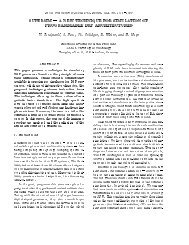
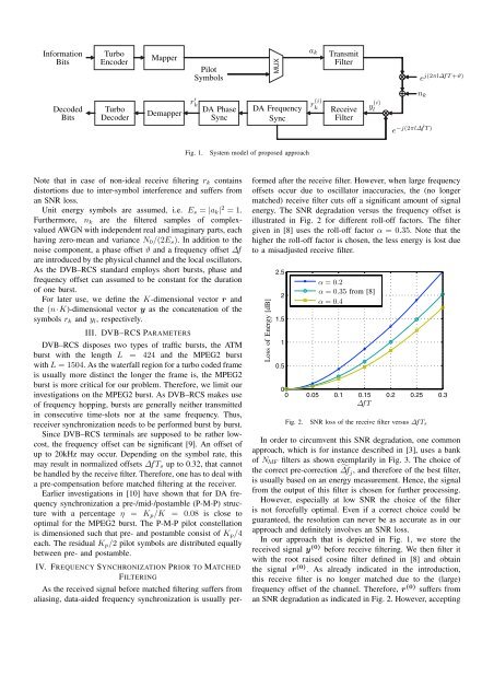
Inform<strong>at</strong>ionBitsTurboEncoderMapperPilotSymbolsMUXa kTransmitFiltere j(2πl∆fT+ϑ)DecodedBitsTurboDecoderDemapperr ′ kDA PhaseSyncDA <strong>Frequency</strong>Syncr (i)kReceiveFiltery (i)ln ke −j(2πl∆ˆfT)Fig. 1.System model <strong>of</strong> proposed approachNote th<strong>at</strong> in case <strong>of</strong> non-ideal receive filtering r k containsdistortions due to inter-symbol interference and suffers froman SNR loss.Unit energy symbols are assumed, i.e. E s = |a k | 2 =1.Furthermore, n k are the filtered samples <strong>of</strong> complexvaluedAWGN with independent real and imaginary parts, eachhaving zero-mean and variance N 0 /(2E s ). In addition to thenoise component, a phase <strong>of</strong>fset ϑ and a frequency <strong>of</strong>fset ∆fare introduced by the physical channel and the local oscill<strong>at</strong>ors.As the DVB–RCS standard employs short bursts, phase andfrequency <strong>of</strong>fset can assumed to be constant for the dur<strong>at</strong>ion<strong>of</strong> one burst.For l<strong>at</strong>er use, we define the K-dimensional vector r andthe (n·K)-dimensional vector y as the conc<strong>at</strong>en<strong>at</strong>ion <strong>of</strong> thesymbols r k and y l , respectively.III. DVB–RCS PARAMETERSDVB–RCS disposes two types <strong>of</strong> traffic bursts, the ATMburst with the length L = 424 and the MPEG2 burstwith L = 1504. As the w<strong>at</strong>erfall region for a turbo coded frameis usually more distinct the longer the frame is, the MPEG2burst is more critical for our problem. Therefore, we limit ourinvestig<strong>at</strong>ions on the MPEG2 burst. As DVB–RCS makes use<strong>of</strong> frequency hopping, bursts are generally neither transmittedin consecutive time-slots nor <strong>at</strong> the same frequency. Thus,receiver synchroniz<strong>at</strong>ion needs to be performed burst by burst.Since DVB–RCS terminals are supposed to be r<strong>at</strong>her lowcost,the frequency <strong>of</strong>fset can be significant [9]. An <strong>of</strong>fset <strong>of</strong>up to 20kHz may occur. Depending on the symbol r<strong>at</strong>e, thismay result in normalized <strong>of</strong>fsets ∆f T s up to 0.32, th<strong>at</strong> cannotbe handled by the receive filter. Therefore, one has to deal witha pre-compens<strong>at</strong>ion before m<strong>at</strong>ched filtering <strong>at</strong> the receiver.Earlier investig<strong>at</strong>ions in [10] have shown th<strong>at</strong> for DA frequencysynchroniz<strong>at</strong>ion a pre-/mid-/postamble (P-M-P) structurewith a percentage η = K p /K = 0.08 is close tooptimal for the MPEG2 burst. The P-M-P pilot constell<strong>at</strong>ionis dimensioned such th<strong>at</strong> pre- and postamble consist <strong>of</strong> K p /4each. The residual K p /2 pilot symbols are distributed equallybetween pre- and postamble.IV. FREQUENCY SYNCHRONIZATION PRIOR TO MATCHEDFILTERINGAs the received signal before m<strong>at</strong>ched filtering suffers fromaliasing, d<strong>at</strong>a-aided frequency synchroniz<strong>at</strong>ion is usually performedafter the receive filter. However, when large frequency<strong>of</strong>fsets occur due to oscill<strong>at</strong>or inaccuracies, the (no longerm<strong>at</strong>ched) receive filter cuts <strong>of</strong>f a significant amount <strong>of</strong> signalenergy. The SNR degrad<strong>at</strong>ion versus the frequency <strong>of</strong>fset isillustr<strong>at</strong>ed in Fig. 2 for different roll-<strong>of</strong>f factors. The filtergiven in [8] uses the roll-<strong>of</strong>f factor α =0.35. Note th<strong>at</strong> thehigher the roll-<strong>of</strong>f factor is chosen, the less energy is lost dueto a misadjusted receive filter.Loss <strong>of</strong> Energy [dB]2.521.510.5α =0.2α =0.35 from [8]α =0.400 0.05 0.1 0.15 0.2 0.25 0.3∆f TFig. 2.SNR loss <strong>of</strong> the receive filter versus ∆f T sIn order to circumvent this SNR degrad<strong>at</strong>ion, one commonapproach, which is for instance described in [3], uses a bank<strong>of</strong> N MF filters as shown exemplarily in Fig. 3. The choice <strong>of</strong>the correct pre-correction ˜∆f j , and therefore <strong>of</strong> the best filter,is usually based on an energy measurement. Hence, the signalfrom the output <strong>of</strong> this filter is chosen for further processing.However, especially <strong>at</strong> low SNR the choice <strong>of</strong> the filteris not forcefully optimal. Even if a correct choice could beguaranteed, the resolution can never be as accur<strong>at</strong>e as in ourapproach and definitely involves an SNR loss.In our approach th<strong>at</strong> is depicted in Fig. 1, we store thereceived signal y (0) before receive filtering. We then filter itwith the root raised cosine filter defined in [8] and obtainthe signal r (0) . As already indic<strong>at</strong>ed in the introduction,this receive filter is no longer m<strong>at</strong>ched due to the (large)frequency <strong>of</strong>fset <strong>of</strong> the channel. Therefore, r (0) suffers froman SNR degrad<strong>at</strong>ion as indic<strong>at</strong>ed in Fig. 2. However, accepting