Automatic ADL-based Operand Isolation for Embedded Processors
Automatic ADL-based Operand Isolation for Embedded Processors
Automatic ADL-based Operand Isolation for Embedded Processors

Create successful ePaper yourself
Turn your PDF publications into a flip-book with our unique Google optimized e-Paper software.
<strong>Automatic</strong> <strong>ADL</strong>-<strong>based</strong> <strong>Operand</strong> <strong>Isolation</strong> <strong>for</strong> <strong>Embedded</strong> <strong>Processors</strong><br />
A. Chattopadhyay, B. Geukes, D. Kammler, E. M. Witte, O. Schliebusch, H. Ishebabi,<br />
R. Leupers, G. Ascheid, H. Meyr<br />
Integrated Signal Processing Systems<br />
RWTH Aachen University 52056 Aachen, Germany<br />
anupam@iss.rwth-aachen.de<br />
Abstract<br />
Cutting-edge applications of future embedded systems demand<br />
highest processor per<strong>for</strong>mance with low power consumption to get<br />
acceptable battery-life times. There<strong>for</strong>e, low power optimization<br />
techniques are strongly applied during the development of modern<br />
Application Specific Instruction Set <strong>Processors</strong> (ASIPs). Electronic<br />
System Level design tools <strong>based</strong> on Architecture Description Languages<br />
(<strong>ADL</strong>) offer a significant reduction in design time and ef<strong>for</strong>t<br />
by automatically generating the software tool-suite as well as<br />
the Register Transfer Level (RTL) description of the processor. In<br />
this paper, the automation of power optimization in <strong>ADL</strong>-<strong>based</strong> RTL<br />
generation is addressed.<br />
<strong>Operand</strong> isolation is a well-known power optimization technique<br />
applicable at all stages of processor development. With increasing<br />
design complexitiy several ef<strong>for</strong>ts have been undertaken to automate<br />
operand isolation. In pipelined datapaths, where isolating signals<br />
are often implicitly available, the traditional RTL-<strong>based</strong> approach<br />
introduces unnecessary overhead. We propose an approach which<br />
extracts high-level structural in<strong>for</strong>mation from the <strong>ADL</strong> representation<br />
and systematically uses the available control signals. Our<br />
experiments with state-of-the-art embedded processors show a significant<br />
power reduction (improvement in power efficiency).<br />
1. Introduction<br />
Nowadays, ASIPs are ubiquitous due to the unique combination<br />
of per<strong>for</strong>mance and flexibility offered by them. <strong>ADL</strong>s [8] [2] are<br />
employed to model the ASIP in a higher level of abstraction than<br />
RTL, thereby reducing the design ef<strong>for</strong>t significantly. The architectural<br />
in<strong>for</strong>mation available in this high-level abstraction has been<br />
successfully used to optimize the processor [13] in terms of area<br />
or delay. However, effective power reduction techniques using the<br />
<strong>ADL</strong>-<strong>based</strong> description are yet to be explored. On the other hand,<br />
demand <strong>for</strong> power-efficiency, especially <strong>for</strong> mobile hand-held embedded<br />
systems, is growing strongly.<br />
Power-specific optimizations can be applied at all levels of abstraction<br />
during a processor design. In the gate-level design, low<br />
power can be achieved by introducing specially designed cell libraries,<br />
at the RTL by introducing selective blocking of operands<br />
or at the system level by shutting off sections of the design. In principle,<br />
the power optimization techniques can be classified into two<br />
major categories. In one group of power optimization techniques,<br />
the dynamic power of a design is controlled by reducing the clocking<br />
activity of the sequential elements. Exemplarily, Clock gating<br />
[11] is a power-reduction technique <strong>based</strong> on the above principle,<br />
which disables the clock entering into a register whenever an unnecessary<br />
storage takes place. In the other group, the combinational<br />
components of a design are controlled in order to minimize power<br />
consumption. <strong>Operand</strong> <strong>Isolation</strong> is one such technique. Employing<br />
operand isolation, redundant combinational blocks of a design<br />
are identified. Here, redundant means in temporal perspective i.e.<br />
a combinational operation is per<strong>for</strong>med at a particular time, when<br />
its result is not getting used in the downstream circuit. By operand<br />
isolation, these temporarily redundant operations are identified and<br />
the operands of these operations are held at a particular value to<br />
reduce the switching activity of the combinational circuit. This,<br />
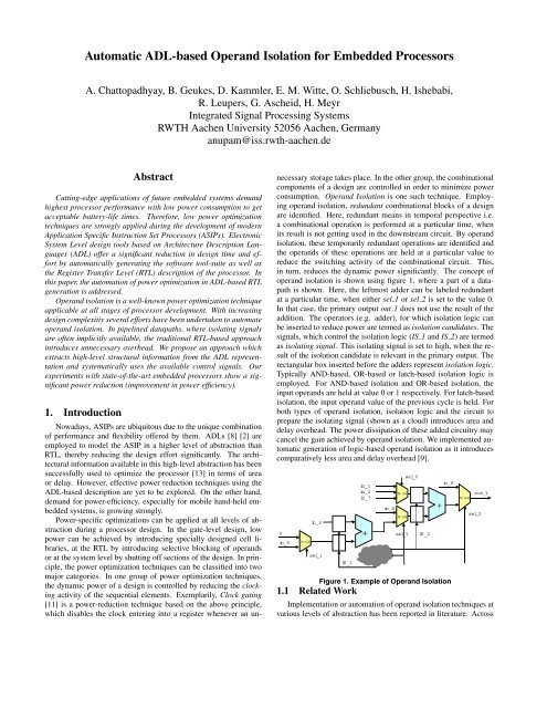
in turn, reduces the dynamic power significantly. The concept of<br />
operand isolation is shown using figure 1, where a part of a datapath<br />
is shown. Here, the leftmost adder can be labeled redundant<br />
at a particular time, when either sel 1 or sel 2 is set to the value 0.<br />
In that case, the primary output out 1 does not use the result of the<br />
addition. The operators (e.g. adder), <strong>for</strong> which isolation logic can<br />
be inserted to reduce power are termed as isolation candidates. The<br />
signals, which control the isolation logic (IS 1 and IS 2) are termed<br />
as isolating signal. This isolating signal is set to high, when the result<br />
of the isolation candidate is relevant in the primary output. The<br />
rectangular box inserted be<strong>for</strong>e the adders represent isolation logic.<br />
Typically AND-<strong>based</strong>, OR-<strong>based</strong> or latch-<strong>based</strong> isolation logic is<br />
employed. For AND-<strong>based</strong> isolation and OR-<strong>based</strong> isolation, the<br />
input operands are held at value 0 or 1 respectively. For latch-<strong>based</strong><br />
isolation, the input operand value of the previous cycle is held. For<br />
both types of operand isolation, isolation logic and the circuit to<br />
prepare the isolating signal (shown as a cloud) introduces area and<br />
delay overhead. The power dissipation of these added circuitry may<br />
cancel the gain achieved by operand isolation. We implemented automatic<br />
generation of logic-<strong>based</strong> operand isolation as it introduces<br />
comparatively less area and delay overhead [9].<br />
0<br />
in_5<br />
mux<br />
in_3<br />
sel_1<br />
IS_1<br />
in_1<br />
in_2<br />
in_7<br />
+<br />
mux<br />
in_8<br />
mux<br />
sel_1<br />
sel_0<br />
IS_2<br />
+<br />
in_9<br />
mux<br />
out_1<br />
sel_2<br />
Figure 1. Example of <strong>Operand</strong> <strong>Isolation</strong><br />
1.1 Related Work<br />
Implementation or automation of operand isolation techniques at<br />
various levels of abstraction has been reported in literature. Across
abstraction levels, the issues faced in operand isolation are quite similar<br />
in nature. First, one has to select the candidates <strong>for</strong> operand<br />
isolation. Second, the isolating signal has to be created or re-used<br />
from existing circuitry. Finally, the isolation logic has to be inserted<br />
in a suitable position of the circuit. The existing operand isolation<br />
approaches at different abstraction levels can be reviewed in the perspective<br />
of the three abovementioned steps.<br />
During the implementation of IBM PowerPC 4xx microcontrollers,<br />
operand isolation has been implemented manually [4].<br />
There, nothing specific is mentioned about the candidate selection.<br />
Typically the isolation candidates are shown to reside be<strong>for</strong>e a result<br />
bus multiplexer and the control signal of the multiplexer is re-used as<br />
the isolating signal (figure 4 of [4]). The isolating logic is inserted<br />
immediately be<strong>for</strong>e the isolation candidate. Tiwari et al [17] per<strong>for</strong>med<br />
operand isolation automatically at gate-level. The approach<br />
exploits the gate-level granularity by allowing the isolation to be<br />
per<strong>for</strong>med over any arbitrary logic circuit. The existing control signals<br />
are directly used as isolating signal and the isolation candidate<br />
is selected on the basis of potential power savings. The isolation<br />
logic is inserted at a point of circuit, where the isolating signal arrives<br />
pretty earlier than the actual transition. This way of derivation<br />
of the isolating signal limits the scope of identification of possible<br />
isolation candidates. In a recent work by Banerjee et al [10], novel<br />
gate-level circuits are introduced to per<strong>for</strong>m operand isolation. This<br />
approach requires special cells to per<strong>for</strong>m operand isolation and it<br />
can be complemented with high-level operand isolation schemes.<br />
The approach adopted by Münch et al [9] allows automated RTL<strong>based</strong><br />
operand isolation. In this approach, the isolation candidates<br />
are determined on the basis of a detailed power model. The isolating<br />
signal is created out of a circuit <strong>based</strong> on the output Observability<br />
Don’t Care (ODC) conditions of the isolation candidates. The<br />
concept of ODC can be explained using figure 1. In case of the<br />
rightmost adder of the figure 1, the result of the addition is not observable<br />
at out 1 when sel 2 is 0. There<strong>for</strong>e, <strong>for</strong> the input operands<br />
of the adder, the ODC is simply sel 2. InMünch’s approach, the isolating<br />
signal <strong>for</strong> each input operand of an operator is generated from<br />
the operator’s output ODC. For a large datapath block, the primary<br />
inputs and outputs are defined by partitioning the complete circuit<br />
across sequential logic boundaries.<br />
<strong>Operand</strong> <strong>Isolation</strong> techniques have been incorporated during<br />
high-level synthesis, too. In the approach mentioned at [6], operand<br />
isolation is per<strong>for</strong>med independent of other high-level synthesis<br />
tasks and a blocking latch is inserted be<strong>for</strong>e the functional units.<br />
Details of isolating signal generation or isolation candidate selection<br />
are not presented. In the context of <strong>ADL</strong>-<strong>based</strong> high-level synthesis,<br />
the RTL generator GO [16], <strong>based</strong> on the <strong>ADL</strong> nML [1], is known<br />
to contain power-specific optimizations like disabling of functional<br />
units. Any detailed analyses of these optimizations are not publicly<br />
available.<br />
1.2 Motivation<br />
With the above discussion about available operand isolation approaches,<br />
the motivation of this work is now presented. A key issue<br />
in operand isolation is the derivation of the isolating signal itself.<br />
Consider figure 2 <strong>for</strong> example.<br />
Here the steering signals (in steer 1 and in steer 2) are primary<br />
inputs of the datapath block. The steering signals along with the<br />
result of a local addition produce the multiplexer controlling signal<br />
sel 2 through a selection logic. As mentioned by Münch et al [9],<br />
the derivation of the relevant steering signals from the complex RTL<br />
structure is often impossibly difficult. The approach taken in [9] is<br />
to use the multiplexer control signals (e.g. sel 1) and to derive a<br />
logic circuit generating the isolating signal. Obviously, the insertion<br />
of logic circuit introduces area and delay overhead. In case of this<br />
0<br />
in_5<br />
in_steer_1<br />
mux<br />
Selection<br />
logic<br />
in_3<br />
sel_1<br />
in_steer_2<br />
in_1<br />
in_2<br />
+<br />
in_6<br />
mux<br />
mux<br />
sel_0<br />
sel_1<br />
+<br />
in_7<br />
mux<br />
out_1<br />
sel_2<br />
Selection<br />
logic<br />
in_steer_1<br />
in_steer_2<br />
Figure 2. Motivation <strong>for</strong> <strong>ADL</strong>-<strong>based</strong> <strong>Operand</strong> <strong>Isolation</strong><br />
overhead being significant the operand isolation is not per<strong>for</strong>med<br />
at all. Thus the trade-off between power, area and delay is heavily<br />
biased. Either the isolation is done at finest granularity or not<br />
done at all. In this paper, this flexibility is introduced by deriving<br />
the steering signals from high level architectural in<strong>for</strong>mation. For<br />
low-overhead coarse-grained operand isolation, the steering signal<br />
is directly used as an isolating signal. Alternatively, with the knowledge<br />
of the dataflow in the datapath blocks, ODC-<strong>based</strong> operand<br />
isolation can be implemented. In summary, the major contribution<br />
of this paper is to present:<br />
• An automatic <strong>ADL</strong>-<strong>based</strong> operand isolation framework.<br />
• A flexible operand isolation approach <strong>for</strong> pipelined processors.<br />
In addition to these, we propose a minor extension to the ODC<strong>based</strong><br />
operand isolation algorithm. Consider previous figure 1. Following<br />
the ODC-<strong>based</strong> approach outlined at [9], the isolation logic<br />
will be placed immediately be<strong>for</strong>e the isolation candidates. However,<br />
the cases where the input is already blocked <strong>for</strong> similar conditions<br />
do not need another isolation. As in figure 1, IS 1 is derived<br />
correctly from sel 1 and sel 2 (as in ODC-<strong>based</strong> approach), whereas<br />
sel 1 is already used to isolate in 5. These situations often occur<br />
<strong>for</strong> datapath involving bit-masking operations. Clearly, the isolation<br />
logic is redundant considering logic-<strong>based</strong> isolation. We identified<br />
this redundancy manually in the generated RTL description and<br />
eliminated the isolation overhead. A low overhead in isolation, in<br />
turn, results in further power reduction.<br />
The rest of the paper is organized as follows: section 2 discusses the<br />
relevant features of <strong>ADL</strong> LISA, which is used <strong>for</strong> this work. Section<br />
3 describes the framework <strong>for</strong> low power optimization. In section 4,<br />
the automatic generation of operand isolation from the <strong>ADL</strong> is described<br />
in detail. Section 5 elaborates and analyzes our case study.<br />
We conclude with the summary and outlook.<br />
2. <strong>ADL</strong> Structure Overview<br />
In this section, a brief overview of the <strong>ADL</strong> LISA [8] is provided.<br />
Furthermore, the relevant language elements and their corresponding<br />
mapping to a processor are discussed.<br />
2.1 LISA Operation Graph<br />
In LISA, an operation is the central element to describe the timing<br />
and the behavior of a processor instruction. The instruction may<br />
be split among several LISA operations. The resources (registers,<br />
memories, pins etc.) are declared globally in the resource section,<br />
which can be accessed from any LISA operation.<br />
The LISA description is <strong>based</strong> on the principle that a specific<br />
common behavior or common instruction encoding is described in<br />
a single operation whereas the specialized behavior or encoding is
'HFRGHVWDJH<br />
Decode<br />
Top-levelDesign<br />
Pipeline<br />
move_reg_steer<br />
mul_steer<br />
([HFXWHVWDJH<br />
ADD<br />
Arithm etic<br />
SUB<br />
FE DC EX W B<br />
D ecoder<br />
D ecoder<br />
Decoder<br />
func_1<br />
func_2<br />
func_3<br />
func_fetch<br />
:ULWHEDFNVWDJH<br />
Writeback<br />
Figure 3. LISA Operation DAG<br />
implemented in its child operations. Specialized operations may be<br />
referred to by more than one parent operation. The complete structure<br />
is a Directed Acyclic Graph (DAG) D = 〈V,E〉. V represents<br />
the set of LISA operations, E the graph edges as set of child-parent<br />
relations. These relations represent activations, which refer to the<br />
execution of another LISA operation. Figure 3 gives an example of<br />
a LISA operation DAG. As shown, the operations can be distributed<br />
over several pipeline stages. A chain of operations, <strong>for</strong>ming a complete<br />
branch of the LISA operation DAG represents an instruction in<br />
the modelled processor. A LISA Operation contains different subsections<br />
to capture the entire processor behavior. The ones relevant<br />
<strong>for</strong> RTL synthesis are discussed below.<br />
Instruction Coding Description: The instruction encoding of a<br />
LISA operation is described as a sequence of coding fields. Each<br />
coding field is either a terminal bit sequence with “0”, “1”, “don’t<br />
care”(X) bits or a nonterminal bit sequence referring to the coding<br />
field of another child LISA operation.<br />
Activations: A LISA operation can activate other operations in<br />
the same or a later pipeline stage. In either case, the child operation<br />
may be activated directly or via a group. A group collects several<br />
LISA operations, with the elements being mutually exclusive. The<br />
elements are distinguished by a unique binary coding, <strong>for</strong>ming a<br />
coding tree. The activation and instruction coding tree jointly <strong>for</strong>m<br />
the decoder in the target processor. The activation chain also provides<br />
valuable in<strong>for</strong>mation regarding the dataflow in the complete<br />
processor. The activation edge is trans<strong>for</strong>med as a major steering<br />
signal in the processor datapath. For each LISA operation, a corresponding<br />
steering signal is existent. The instruction coding tree<br />
generates minor steering signals within the scope of one LISA Operation.<br />
Behavior Description: The behavior description of a LISA operation<br />
corresponds to the datapath of the processor. Inside the behavior<br />
description plain C code can be used. Resources such as registers,<br />
memories, signals and pins as well as coding elements can be<br />
accessed in the same way as ordinary variables. The behavior section<br />
of every LISA operation is trans<strong>for</strong>med into a functional block<br />
in the RTL datapath.<br />
3. Power Optimization Framework<br />
Be<strong>for</strong>e elaborating on the power-<strong>based</strong> optimization framework,<br />
a typical pipelined processor structure is explained. In the remaining<br />
part of this section, we introduce the data flow graph, which is used<br />
<strong>for</strong> operand isolation.<br />
3.1 Processor Structure<br />
The figure 4 shows a typical simplescalar pipelined processor<br />
structure. The detailed connections are avoided <strong>for</strong> simplicity. The<br />
pipeline is divided into 4 stages. In this processor, the register file is<br />
residing outside the pipeline. In this implementation, the decoder is<br />
distributed over the complete pipeline. For each datapath block, the<br />
local decoder issues a major steering signal. Corresponding to the<br />
<strong>ADL</strong> elements discussed in the previous section, the activation and<br />
Pipeline C ontro ler<br />
MemoryFile<br />
write_op1<br />
operand1<br />
move_reg<br />
mul<br />
read<br />
RegisterFile<br />
operand1<br />
write_reg<br />
Figure 4. Pipelined Processor with Distributed Decoding<br />
the instruction coding jointly contributes to this decoder <strong>for</strong>mation.<br />
Clearly, <strong>ADL</strong>-<strong>based</strong> RTL synthesis allows an easy access to highlevel<br />
structural in<strong>for</strong>mation in order to identify the steering signals<br />
from a complex logic structure. For detailed understanding of RTL<br />
processor synthesis from <strong>ADL</strong>s, please refer to [13] and/or [12].<br />
Note that, it is possible to derive and use these steering signals<br />
<strong>for</strong> other pipeline organizations, too. For a pipeline with centralized<br />
decoder, the steering signals need to be propagated to the relevant<br />
datapath. This concept of using steering signals <strong>for</strong> pipelined datapaths<br />
has been succesfully used <strong>for</strong> clock gating in [7]. However,<br />
no automatic approach is available. Understandably, it is difficult to<br />
derive these signals from complex RTL structure.<br />
As observed in [9], the ODC-<strong>based</strong> operand isolation algorithms<br />
become extremely complex if the complete design is considered <strong>for</strong><br />
ODC calculation. A much simpler and effective approach is to partition<br />
the datapath with the sequential cells in the boundary and then<br />
apply operand isolation locally. In the context of pipelined processors,<br />
this partition occurs naturally within one stage. The operand<br />
isolation algorithms are applied within these partitions i.e. within<br />
the scope of one LISA operation.<br />
3.2 Behavioral Data Flow Graph<br />
Inside a single LISA operation, the behavior section guides the<br />
data flow. The behavior section of a LISA operation is converted into<br />
a pure, directed acyclic Data Flow Graph (DFG). The graph vertices<br />
of G DFG = 〈V op,E ic〉 are the basic operators <strong>for</strong> data manipulation<br />
e.g. additions while edges represent the flow of unchanged data in<br />
<strong>for</strong>m of interconnections of inputs and outputs.<br />
Operators: The following list summarizes the basic classes of<br />
operators represented by graph vertices. This special choice of vertices<br />
allows us to represent the data flow in<strong>for</strong>mation in a level between<br />
RTL and logic-level representation. In that way, our representation<br />
is close to Bergamaschi’s Behavioral Network Graph [5].<br />
• Commutative n-ary Operator, n ≥ 2<br />
• Noncommutative n-ary Operator, n ≥ 1<br />
• Read Access to Registers and Memories<br />
• Write Access to Registers and Memories<br />
• Read and Write Access to Array of Variable<br />
• Multiplexer<br />
Interconnections: Interconnections represent the data flow on<br />
symbol-level opposed to bit-level representations used in gate-level<br />
synthesis. The in<strong>for</strong>mation about the data type transferred is given<br />
by an annotation to the interconnection. Bit range subscriptions are<br />
included into the interconnection in<strong>for</strong>mation, too.<br />
The creation of the DFG from the plain C-code of a LISA operation’s<br />
behavior section is shown in figure 5. As depicted there,<br />
read
,6$'DWD)ORZ<br />
OPERATION decode {<br />
ACTIVATION {ld}<br />
}<br />
OPERATION ld {<br />
BEHAVIOR {<br />
int a = 5;<br />
if (res_b == 1) {<br />
R[0] = a;<br />
} else {<br />
R[0] = res_c;<br />
}<br />
}}<br />
ld_steer<br />
ew _R<br />
')*UHSUHVHQWDWLRQ<br />
res_b<br />
0<br />
addr_R<br />
5<br />
data_R<br />
res_c<br />
1 0<br />
Figure 5. Example of Data Flow Graph Creation<br />
the DFG is constructed after per<strong>for</strong>ming basic compiler-like optimizations.<br />
In this case, the constant value of local variable a is<br />
propagated. For the read access to non-array registers e.g. res c,<br />
we need not pass any address value. For the write access to a onedimensional<br />
resource R, the write enable and the address value is set<br />
in the scope of the same vertex. The value <strong>for</strong> write enable is set to<br />
ld steer, which indicates that this operation is to be executed or not.<br />
4. <strong>Automatic</strong> <strong>Operand</strong> <strong>Isolation</strong><br />
In this section, different operand isolation techniques are explained.<br />
The isolation constraints used during automatic operand<br />
isolation are mentioned. Finally, the algorithms <strong>for</strong> instantiating<br />
operand isolations are outlined and the overall flow is presented.<br />
4.1 <strong>Operand</strong> <strong>Isolation</strong> Techniques<br />
In figure 6, there is one major steering input (indicative of the<br />
complete datapath block execution) and one minor steering input<br />
(in steer local), which is used within the context of this datapath<br />
block. Both the steering inputs are directly available as primary inputs.<br />
The steering inputs are fed into combinational logic (shown<br />
as cloud) to prepare the multiplexer controlling signals sel 1 and the<br />
enable signal <strong>for</strong> a target register.<br />
0<br />
in_3<br />
in_steer<br />
in_steer_local<br />
0<br />
in_2<br />
mux<br />
sel_1<br />
sel_2<br />
mux<br />
in_1<br />
+<br />
sel_1<br />
mux<br />
enable<br />
mux<br />
Figure 6. Datapath without <strong>Operand</strong> <strong>Isolation</strong><br />
Register<br />
clock<br />
Coarse-grained <strong>Operand</strong> <strong>Isolation</strong>: To per<strong>for</strong>m coarse-grained<br />
operand isolation, we rely completely on the major steering signal<br />
<strong>for</strong> the datapath block. A coarse-grained isolation over the complete<br />
datapath block can be done as shown in figure 7. Obviously, blocking<br />
the primary inputs leading to a simple logic gate will not be beneficial.<br />
There<strong>for</strong>e, one needs to identify the operators and bit-widths<br />
within the scope of a datapath partition, <strong>for</strong> which the isolation is to<br />
be done. In order to allow this selective isolation, several high-level<br />
constraints can be introduced, which are discussed afterwards.<br />
isolating signal<br />
isolation logic<br />
0<br />
in_3<br />
in_steer_local<br />
0<br />
mux<br />
in_steer<br />
in_2<br />
sel_1<br />
sel_2<br />
mux<br />
in_1<br />
+<br />
sel_1<br />
mux<br />
enable<br />
mux<br />
Register<br />
clock<br />
Figure 7. Datapath with Coarse-grained <strong>Operand</strong> <strong>Isolation</strong><br />
ODC-<strong>based</strong> <strong>Operand</strong> <strong>Isolation</strong>: For ODC-<strong>based</strong> operand isolation,<br />
the Observability Don’t Cares of the primary outputs need to<br />
be considered. In this case, there is only one primary output (input<br />
of register). Traversing back from the enable signal of the primary<br />
output allows to create an isolating signal <strong>for</strong> the input operands of<br />
given logic blocks (as shown in figure 8). The isolating signals <strong>for</strong><br />
all the input operands are derived to be the same. In this case, <strong>for</strong> the<br />
adder inputs, the isolating signal is obtained by per<strong>for</strong>ming logical<br />
and operation between sel 1 and enable.<br />
0<br />
0<br />
in_2<br />
in_3<br />
in_steer<br />
in_steer_local<br />
mux<br />
mux<br />
sel_2<br />
sel_1<br />
in_1<br />
+<br />
sel_1<br />
mux<br />
enable<br />
mux<br />
Register<br />
clock<br />
Figure 8. Datapath with ODC-<strong>based</strong> <strong>Operand</strong> <strong>Isolation</strong><br />
Fine-grained <strong>Operand</strong> <strong>Isolation</strong>: For this technique, the ODC<strong>based</strong><br />
isolation procedure is extended by considering the bitmasking<br />
at the input operands of the isolation candidates. As can<br />
be observed in figure 9, one input operand <strong>for</strong> the adder is held constant<br />
by a controlling signal (sel 1) also used in a later multiplexer.<br />
There<strong>for</strong>e, it is sufficient to use enable as isolating signal. However,<br />
the same is not true <strong>for</strong> the input operand in 2 where sel 2 is the controlling<br />
signal. In this case, the area overhead will increase if sel 2 is<br />
included in the isolating signal circuit. Hence, fine-grained operand<br />
isolation is useful only in the cases where the input operand is held<br />
constant under a condition, already included in the ODC condition.<br />
0<br />
0<br />
in_2<br />
in_3<br />
sel_1<br />
in_steer<br />
in_steer_local<br />
mux<br />
mux<br />
sel_2<br />
+<br />
in_1<br />
sel_1<br />
mux<br />
enable<br />
mux<br />
Register<br />
clock<br />
Figure 9. Datapath with Fine-grained <strong>Operand</strong> <strong>Isolation</strong><br />
4.2 <strong>Isolation</strong> Constraints<br />
In some automated operand isolation approaches, a detailed<br />
power model has been considered <strong>for</strong> inserting operand isolation<br />
among isolation candidates [9]. The approach presented in this<br />
paper is integrated in a high-level synthesis framework, where the<br />
proper estimation of per<strong>for</strong>mance itself is a huge research area. We<br />
adopted an alternative approach by allowing several high-level constraints<br />
be<strong>for</strong>e inserting operand isolation. These constraints, unlike<br />
the model-<strong>based</strong> approach, grant more user interaction and there<strong>for</strong>e<br />
stronger control over the trade-offs. A brief summary of the<br />
constraints is mentioned here.<br />
<strong>Isolation</strong> Prevention: A complete data flow block can be spared<br />
from operand isolation by inserting pragma in the <strong>ADL</strong> description.<br />
This is useful <strong>for</strong> dataflow blocks with high execution frequency.<br />
Operator Selection: Selected operators can be pointed <strong>for</strong><br />
operand isolation candidacy. For example, one can select only<br />
adders and multipliers to be isolated.<br />
Bit-width Selection: A minimum bit-width (of operator) can be<br />
specified <strong>for</strong> being selected as an isolation candidate.
4.3 Algorithms <strong>for</strong> <strong>Automatic</strong> <strong>Operand</strong> <strong>Isolation</strong><br />
Here, the <strong>ADL</strong>-<strong>based</strong> coarse-grained and ODC-<strong>based</strong> operand<br />
isolation algorithms are outlined. Subsequently, the computation<br />
complexity <strong>for</strong> the algorithms are shown.<br />
01 // In a pipeline stage, DP j denotes a datapath block<br />
02 // DP j is completely represented by a dataflow graph<br />
03 // node k denotes a vertex of the dataflow graph<br />
04 // pi k denotes a primary input corresponding to node k<br />
05<br />
06 InstantiateCoarseGrained<strong>Operand</strong><strong>Isolation</strong>(DP j ) {<br />
07 // each datapath block can be stopped from isolation by a pragma<br />
08 if (DP j is covered by pragma) return;<br />
09 <strong>for</strong> each node k ɛDP j {<br />
10 if (node k satisfies isolation constraints) {<br />
11 S(pi k ) =setof primary inputs(node k )<br />
12 <strong>for</strong> each pi km ɛS(pi k ) {<br />
13 if (pi km is not already isolated) {<br />
14 isolating signal = steering signal(DP j)<br />
15 insert isolation logic(pi km , isolating signal )<br />
16 }}}}}<br />
The coarse-grained operand isolation algorithm during <strong>ADL</strong>driven<br />
high level synthesis is outlined in the above pseudo-code. For<br />
each datapath block, the nodes which satisfy given isolation constraints<br />
are treated. For every such node, primary inputs are tracked<br />
back and the isolation logic is coupled with the primary inputs. The<br />
isolating signal is given by the major steering signal of the datapath<br />
block, which is directly available via high-level structural in<strong>for</strong>mation.<br />
The runtime complexity of the above algorithm is determined<br />
by the loop over primary inputs (line 12). For a dataflow graph with<br />
n nodes, the worst case complexity is O(n 2 ).<br />
The following pseudo-code contains the essence of the ODC<strong>based</strong><br />
operand isolation algorithm. The ODC is propagated from<br />
the datapath block’s primary outputs to the isolation candidate’s input<br />
operands. The isolating signal is derived from the ODC itself.<br />
The runtime complexity of the above algorithm is determined by<br />
the computation of the ODC <strong>for</strong> each input operand of the isolation<br />
node. ODC propagation per node is done in linear complexity. Considering<br />
the number of input operands per operator to be p,theworst<br />
case complexity is O(p · n 2 ).<br />
01 // In a pipeline stage, DP j denotes a datapath block<br />
02 // DP j is completely represented by a dataflow graph<br />
03 // node k denotes a vertex of the dataflow graph<br />
04 // po k denotes a primary output corresponding to node k<br />
05<br />
06 InstantiateFineGrained<strong>Operand</strong><strong>Isolation</strong>(DP j ) {<br />
07 // each datapath block can be stopped from isolation by a pragma<br />
08 if (DP j is covered by pragma) return;<br />
09 <strong>for</strong> each node k ɛDP j {<br />
10 if (node k satisfies isolation constraints) {<br />
11 S(po k ) =setof primary outputs(node k )<br />
12 // calculating Observability Don’t Care<br />
13 ODC out = Propagate ODC(S(po k ), node k )<br />
14 S(i k ) =setof input operands(node k )<br />
15 <strong>for</strong> each i km ɛS(i k ) {<br />
16 isolating signal = ODC out<br />
17 insert isolation logic(i km , isolating signal )<br />
18 }}}}<br />
4.4 Overall Flow<br />
The overall flow of the automatic <strong>ADL</strong>-<strong>based</strong> operand isolation<br />
is shown in the figure 10. A global analysis of a processor’s <strong>ADL</strong><br />
description is done at first. The datapath blocks of the <strong>ADL</strong> in each<br />
pipeline stage is then converted to corresponding DFG representation.<br />
By using the architectural in<strong>for</strong>mation and the isolation constraints,<br />
a designer-selected algorithm is employed to instantiate the<br />
operand isolation. The DFG-representation is then mapped to register<br />
transfer level HDL description via HDL backend. It must be<br />
noted that to map the overall processor structure and the control path<br />
to HDL, various other steps are involved, which are not shown in<br />
this flow. The isolation constraints and the automatic operand isolation<br />
algorithms are integrated into a more elaborate framework <strong>for</strong><br />
<strong>ADL</strong>-drived RTL synthesis.<br />
GlobalStructural<br />
Analysis<br />
RTL Synthesis<br />
<strong>ADL</strong> Description<br />
DFG creation<br />
IRUHDFKGDWDSDWK EORFN<br />
Autom atic O perand <strong>Isolation</strong><br />
Coarse-grained<br />
HDL Backend<br />
ODC-<strong>based</strong><br />
HDL Description<br />
<strong>Isolation</strong><br />
C onstraints<br />
Fine-grained<br />
<strong>Isolation</strong><br />
Figure 10. <strong>ADL</strong>-<strong>based</strong> <strong>Operand</strong> <strong>Isolation</strong> Flow<br />
The selection of the isolation algorithm plays an important role<br />
to minimize the power. Currently, the isolation algorithm can be selected<br />
<strong>for</strong> the overall architecture, whereas it may be more beneficial<br />
to have a different isolation algorithms <strong>for</strong> different datapath blocks.<br />
This extension will be targeted and studied in our future work. Another<br />
important issue is the derivation of the isolation constraints. In<br />
particular, to derive the execution frequencies of datapath blocks, the<br />
designer has to run simulations. With the framework of <strong>ADL</strong>, fast<br />
cycle-accurate instruction-set simulation [3] can be per<strong>for</strong>med. The<br />
instruction-set simulator is automatically generated from the <strong>ADL</strong><br />
description.<br />
5. Case Study<br />
The power optimizations discussed in this paper are tested with<br />
two different ASIPs. The ICORE [15] architecture is dedicated <strong>for</strong><br />
Terrestrial Digital Video Broadcast (DVB-T) decoding. It is <strong>based</strong><br />
on a pipelined Harvard architecture implementing a set of general<br />
purpose arithmetic instructions as well as specialized trigonometric<br />
operations. We took two applications per<strong>for</strong>ming trigonometric<br />
calculations namely, cordic01 and cordic02 running on this architecture.<br />
The second architecture is an ASIP dedicated <strong>for</strong> Fast Fourier<br />
Trans<strong>for</strong>mation (FFT) algorithms. A 32-point FFT application is<br />
used as the test application. Both the ICORE and the FFT architecture<br />
have been developed using LISA. A brief summary of the<br />
architectures is shown in table 1.<br />
Table 1. Summary of the Benchmark Architectures<br />
ICORE FFT<br />
Basis Architecture 32-bit RISC 24-bit RISC<br />
Pipeline Stages 4 6<br />
Lines of LISA Code 2200 1500<br />
Lines of Verilog Code 25200 16600<br />
The LISA models were synthesized to obtain the RTL with and<br />
without various low power optimizations. The automatically generated<br />
RTL description was verified through RTL and gate-level simulation<br />
using Synopsys VCS and then synthesized with Synopsys
Design Compiler, using a 0.13µm technology library. Finally, Synopsys<br />
power measurement flow [14] was employed to measure the<br />
power on gate-level. During the case study, the isolation constraints<br />
have been used to guide the power optimization of the entire processor.<br />
The datapath blocks, which are executed with a high frequency,<br />
have not been considered <strong>for</strong> isolation. The operators with<br />
low bitwidth and less complexity, have been ommitted, too.<br />
<strong>Operand</strong> isolation, by its nature, affects the datapath partitions<br />
strongly. However, in both the architectures, the RegisterFile accounts<br />
<strong>for</strong> a high percentage of the power (65% <strong>for</strong> FFT and 37% <strong>for</strong><br />
ICORE). To determine the clear effect of the operand isolation algorithms,<br />
the power improvements <strong>for</strong> the pipelined datapath is studied.<br />
The best power results obtained <strong>for</strong> both architectures are presented<br />
in table 2. The corresponding changes in area are given, too.<br />
Interestingly, the best power improvements <strong>for</strong> ICORE are available<br />
with ODC-<strong>based</strong> and fine-grained operand isolation, whereas<br />
<strong>for</strong> FFT processor it is the coarse-grained operand isolation. The<br />
reason behind this is the fine-grained operand isolation <strong>for</strong> the FFT<br />
introduced area overhead and thereof power increment, which offsets<br />
the gain. Moreover, <strong>for</strong> FFT, there are some datapath partitions,<br />
which got isolated but are active almost entirely during the application.<br />
Those partitions are identified manually and removed by<br />
inserting pragmas in the <strong>ADL</strong> description.<br />
Table 2. Effect of <strong>Operand</strong> <strong>Isolation</strong> over Pipeline<br />
No <strong>Operand</strong> <strong>Isolation</strong> With <strong>Operand</strong> <strong>Isolation</strong><br />
Benchmark Area Power Area<br />
Power [mW]<br />
[Gates] [mW] [Gates]<br />
cordic01<br />
9.32 34599(+18.71%) 5.41(-41.95%)<br />
29145<br />
cordic02 8.35 34671(+18.96%) 5.79(-30.67%)<br />
fft32 12026 2.66 13198(+9.75%) 2.39(-10.07%)<br />
In the following, a study of the effects of operand isolation in the<br />
overall architecture <strong>for</strong> ICORE is presented. Table 3 summarizes the<br />
power values obtained by applying different isolation algorithms <strong>for</strong><br />
ICORE. The relative improvement of power with respect to the case<br />
of no operand isolation is shown in percentage. As expected, the<br />
coarse-grained isolation algorithm produces least benefit whereas,<br />
in general, the fine-grained operand isolation improves power most.<br />
It must be noted here, that these values reflect the overall architecture<br />
measurement and the power improvement is significantly higher <strong>for</strong><br />
individual datapath partitions.<br />
Table 3. Overall Power (mW) results <strong>for</strong> ICORE<br />
cordic01<br />
cordic02<br />
AND-<strong>based</strong> OR-<strong>based</strong> AND-<strong>based</strong> OR-<strong>based</strong><br />
Original 14.74 13.24<br />
Coarse-grained 11.21(-23.95%) 12.62(-14.38%) 10.80(-18.43%) 12.53(-5.36%)<br />
ODC-<strong>based</strong> 11.14(-24.42%) 12.16(-17.50%) 10.37(-21.68%) 12.41(-8.31%)<br />
Fine-grained 10.97(-25.58%) 12.08(-18.05%) 10.73(-18.96%) 12.04(-9.06%)<br />
Table 4 summarizes the results of area and delay obtained under<br />
different isolation algorithms. The delay due to isolation logic<br />
insertion is never significant. The main underlying reason <strong>for</strong> this<br />
is the datapath blocks in case of ICORE do not have complicated<br />
conditional chains. However, the isolation logic increased the area<br />
significantly <strong>for</strong> all isolation algorithms. Interestingly, the coarsegrained<br />
isolation algorithm resulted in bigger area than fine-grained<br />
or ODC-<strong>based</strong> isolation algorithm. Note that, <strong>for</strong> coarse-grained<br />
operand isolation, the isolation logic appears at the primary inputs.<br />
For ODC-<strong>based</strong> or fine-grained operand isolation, the isolation logic<br />
and isolating signal are generated inside the datapath block, thereby<br />
giving some scope of logic optimization. A closer look revealed that<br />
<strong>for</strong> coarse-grained isolation, such optimizations did not occur. As a<br />
result, the area increase is less compared to coarse-grained operand<br />
isolation.<br />
These results shows that depending on the architecture, the flexibility<br />
to shift between different operand isolation techniques plays a<br />
major role to reap the optimum benefit. Using the high-level archi-<br />
Table 4. Overall Area-Delay results <strong>for</strong> ICORE<br />
Area (Gates)<br />
Delay (ns)<br />
AND-<strong>based</strong> OR-<strong>based</strong> AND-<strong>based</strong> OR-<strong>based</strong><br />
Original 60441 3.90<br />
Coarse-grained 66994 (+10.84%) 66751(+10.44%) 3.96(+1.54%) 3.88(-0.51%)<br />
ODC-<strong>based</strong> 66260 (+9.63%) 64981 (+7.51%) 3.90 (0.00%) 3.89 (-0.26%)<br />
Fine-grained 66147 (+9.44%) 64762 (+7.15%) 3.80 (-2.56%) 3.94 (+1.03%)<br />
tectural in<strong>for</strong>mation, it is possible to achieve a strong reduction in<br />
power and to shift between the coarse-grained power optimization<br />
method (as found in system-level designs) or a fine-grained power<br />
optimization method (as done in RTL abstraction).<br />
6. Summary and Future Work<br />
Growing complexity of cutting-edge embedded processors have<br />
promoted the usage of high processor abstraction level, thus making<br />
the use of system level tooling inevitable. At the same time,<br />
dwindling power budgets <strong>for</strong> modern embedded processors have increased<br />
the significance of power optimization techniques. <strong>Operand</strong><br />
<strong>Isolation</strong>, an effective power reduction technique is explored in this<br />
work from the perspective of <strong>ADL</strong>-<strong>based</strong> processor synthesis.<br />
In our future work, we will focus on the combination of clock<br />
gating and operand isolation and study the power improvements<br />
thereof. We will also extend our framework to include high-level<br />
power models.<br />
7. REFERENCES<br />
[1] A. Fauth et al. Describing Instruction Set <strong>Processors</strong> Using nML. In<br />
Proc. of the European Design and Test Conference (ED&TC), 1995.<br />
[2] A. Halambi, P. Grun, V. Ganesh, A. Khare, N. Dutt and A. Nicolau.<br />
EXPRESSION: A Language <strong>for</strong> Architecture Exploration through<br />
Compiler/Simulator Retargetability. In Proc. of the Conference on<br />
Design, Automation & Test in Europe (DATE), Mar. 1999.<br />
[3] A. Nohl et al. A universal technique <strong>for</strong> fast and flexible<br />
instruction-set architecture simulation. In DAC ’02: Proceedings of<br />
the 39th conference on Design automation, 2002.<br />
[4] Anthony Correale, Jr. Overview of the power minimization techniques<br />
employed in the IBM PowerPC 4xx embedded controllers. In ISLPED<br />
’95: Proceedings of the 1995 international symposium on Low power<br />
design, pages 75–80, New York, NY, USA, 1995. ACM Press.<br />
[5] R. A. Bergamaschi. Behavioral Network Graph: Unifying the<br />
Domains of High-Level and Logic Synthesis. In DAC, 1999.<br />
[6] C. Chen and K. Küçükçakar. An Architectural Power Optimization<br />
Case Study using High-level Synthesis. In ICCD, 1997.<br />
[7] H. Li, S. Bhunia, Y. Chen, T.N. Vijaykumar and K. Roy.<br />
Deterministic Clock Gating <strong>for</strong> Microprocessor Power Reduction. In<br />
Proceedings of the Ninth International Symposium on<br />
High-Per<strong>for</strong>mance Computer Architecture (HPCA).<br />
[8] A. Hoffmann, H. Meyr, and R. Leupers. Architecture Exploration <strong>for</strong><br />
<strong>Embedded</strong> <strong>Processors</strong> with LISA. Kluwer Academic Publishers, 2002.<br />
[9] M. Münch, B. Wurth, R. Mehra, J. Sproch and N. Wehn. Automating<br />
RT-level operand isolation to minimize power consumption in<br />
datapaths. In DATE ’00: Proceedings of the conference on Design,<br />
automation and test in Europe, 2000.<br />
[10] N. Banerjee, A. Raychowdhury, S. Bhunia, H. Mahmoodi and<br />
Kaushik Roy. Novel Low-Overhead <strong>Operand</strong> <strong>Isolation</strong> Techniques <strong>for</strong><br />
Low-Power Datapath Synthesis . In IEEE International Conference<br />
on Computer Design (ICCD), San Jose, Cali<strong>for</strong>nia, USA, October<br />
2005.<br />
[11] P. Babighian, L. Benini and E. Macii. A Scalable ODC-Based<br />
Algorithm <strong>for</strong> RTL Insertion of Gated Clocks. In Proceedings of the<br />
conference on Design, automation and test in Europe, 2004.<br />
[12] P. Mishra, A. Kejariwal and N. Dutt. Synthesis-driven Exploration of<br />
Pipelined <strong>Embedded</strong> <strong>Processors</strong>. In Int. Conf. on VLSI Design, 2004.<br />
[13] Schliebusch, O., Chattopadhyay, A., Witte, E.M., Kammler, D.,<br />
Ascheid, G., Leupers, R. and H. Meyr. Optimization Techniques <strong>for</strong><br />
<strong>ADL</strong>-driven RTL Processor Synthesis. Montreal, Canada, June 2005.<br />
[14] Synopsys. PrimePower<br />
http://www.synopsys.com/products/power/primepower ds.pdf.<br />
[15] T. Gloekler, S. Bitterlich and H. Meyr. ICORE: A Low-Power<br />
Application Specific Instruction Set Processor <strong>for</strong> DVB-T Acquisition<br />
and Tracking. In Proc. of the ASIC/SOC conference, Sep. 2000.<br />
[16] Target Compiler Technologies. http://www.retarget.com.<br />
[17] V. Tiwari, S. Malik and P. Ashar. Guarded Evaluation: Pushing Power<br />
Management to Logic Synthesis/Design. In International Symposium<br />
on Low Power Design, pages 221–226, 1995.