Automatic ADL-based Operand Isolation for Embedded Processors
Automatic ADL-based Operand Isolation for Embedded Processors
Automatic ADL-based Operand Isolation for Embedded Processors

You also want an ePaper? Increase the reach of your titles
YUMPU automatically turns print PDFs into web optimized ePapers that Google loves.
abstraction levels, the issues faced in operand isolation are quite similar<br />
in nature. First, one has to select the candidates <strong>for</strong> operand<br />
isolation. Second, the isolating signal has to be created or re-used<br />
from existing circuitry. Finally, the isolation logic has to be inserted<br />
in a suitable position of the circuit. The existing operand isolation<br />
approaches at different abstraction levels can be reviewed in the perspective<br />
of the three abovementioned steps.<br />
During the implementation of IBM PowerPC 4xx microcontrollers,<br />
operand isolation has been implemented manually [4].<br />
There, nothing specific is mentioned about the candidate selection.<br />
Typically the isolation candidates are shown to reside be<strong>for</strong>e a result<br />
bus multiplexer and the control signal of the multiplexer is re-used as<br />
the isolating signal (figure 4 of [4]). The isolating logic is inserted<br />
immediately be<strong>for</strong>e the isolation candidate. Tiwari et al [17] per<strong>for</strong>med<br />
operand isolation automatically at gate-level. The approach<br />
exploits the gate-level granularity by allowing the isolation to be<br />
per<strong>for</strong>med over any arbitrary logic circuit. The existing control signals<br />
are directly used as isolating signal and the isolation candidate<br />
is selected on the basis of potential power savings. The isolation<br />
logic is inserted at a point of circuit, where the isolating signal arrives<br />
pretty earlier than the actual transition. This way of derivation<br />
of the isolating signal limits the scope of identification of possible<br />
isolation candidates. In a recent work by Banerjee et al [10], novel<br />
gate-level circuits are introduced to per<strong>for</strong>m operand isolation. This<br />
approach requires special cells to per<strong>for</strong>m operand isolation and it<br />
can be complemented with high-level operand isolation schemes.<br />
The approach adopted by Münch et al [9] allows automated RTL<strong>based</strong><br />
operand isolation. In this approach, the isolation candidates<br />
are determined on the basis of a detailed power model. The isolating<br />
signal is created out of a circuit <strong>based</strong> on the output Observability<br />
Don’t Care (ODC) conditions of the isolation candidates. The<br />
concept of ODC can be explained using figure 1. In case of the<br />
rightmost adder of the figure 1, the result of the addition is not observable<br />
at out 1 when sel 2 is 0. There<strong>for</strong>e, <strong>for</strong> the input operands<br />
of the adder, the ODC is simply sel 2. InMünch’s approach, the isolating<br />
signal <strong>for</strong> each input operand of an operator is generated from<br />
the operator’s output ODC. For a large datapath block, the primary<br />
inputs and outputs are defined by partitioning the complete circuit<br />
across sequential logic boundaries.<br />
<strong>Operand</strong> <strong>Isolation</strong> techniques have been incorporated during<br />
high-level synthesis, too. In the approach mentioned at [6], operand<br />
isolation is per<strong>for</strong>med independent of other high-level synthesis<br />
tasks and a blocking latch is inserted be<strong>for</strong>e the functional units.<br />
Details of isolating signal generation or isolation candidate selection<br />
are not presented. In the context of <strong>ADL</strong>-<strong>based</strong> high-level synthesis,<br />
the RTL generator GO [16], <strong>based</strong> on the <strong>ADL</strong> nML [1], is known<br />
to contain power-specific optimizations like disabling of functional<br />
units. Any detailed analyses of these optimizations are not publicly<br />
available.<br />
1.2 Motivation<br />
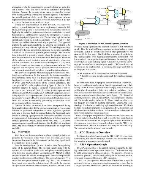
With the above discussion about available operand isolation approaches,<br />
the motivation of this work is now presented. A key issue<br />
in operand isolation is the derivation of the isolating signal itself.<br />
Consider figure 2 <strong>for</strong> example.<br />
Here the steering signals (in steer 1 and in steer 2) are primary<br />
inputs of the datapath block. The steering signals along with the<br />
result of a local addition produce the multiplexer controlling signal<br />
sel 2 through a selection logic. As mentioned by Münch et al [9],<br />
the derivation of the relevant steering signals from the complex RTL<br />
structure is often impossibly difficult. The approach taken in [9] is<br />
to use the multiplexer control signals (e.g. sel 1) and to derive a<br />
logic circuit generating the isolating signal. Obviously, the insertion<br />
of logic circuit introduces area and delay overhead. In case of this<br />
0<br />
in_5<br />
in_steer_1<br />
mux<br />
Selection<br />
logic<br />
in_3<br />
sel_1<br />
in_steer_2<br />
in_1<br />
in_2<br />
+<br />
in_6<br />
mux<br />
mux<br />
sel_0<br />
sel_1<br />
+<br />
in_7<br />
mux<br />
out_1<br />
sel_2<br />
Selection<br />
logic<br />
in_steer_1<br />
in_steer_2<br />
Figure 2. Motivation <strong>for</strong> <strong>ADL</strong>-<strong>based</strong> <strong>Operand</strong> <strong>Isolation</strong><br />
overhead being significant the operand isolation is not per<strong>for</strong>med<br />
at all. Thus the trade-off between power, area and delay is heavily<br />
biased. Either the isolation is done at finest granularity or not<br />
done at all. In this paper, this flexibility is introduced by deriving<br />
the steering signals from high level architectural in<strong>for</strong>mation. For<br />
low-overhead coarse-grained operand isolation, the steering signal<br />
is directly used as an isolating signal. Alternatively, with the knowledge<br />
of the dataflow in the datapath blocks, ODC-<strong>based</strong> operand<br />
isolation can be implemented. In summary, the major contribution<br />
of this paper is to present:<br />
• An automatic <strong>ADL</strong>-<strong>based</strong> operand isolation framework.<br />
• A flexible operand isolation approach <strong>for</strong> pipelined processors.<br />
In addition to these, we propose a minor extension to the ODC<strong>based</strong><br />
operand isolation algorithm. Consider previous figure 1. Following<br />
the ODC-<strong>based</strong> approach outlined at [9], the isolation logic<br />
will be placed immediately be<strong>for</strong>e the isolation candidates. However,<br />
the cases where the input is already blocked <strong>for</strong> similar conditions<br />
do not need another isolation. As in figure 1, IS 1 is derived<br />
correctly from sel 1 and sel 2 (as in ODC-<strong>based</strong> approach), whereas<br />
sel 1 is already used to isolate in 5. These situations often occur<br />
<strong>for</strong> datapath involving bit-masking operations. Clearly, the isolation<br />
logic is redundant considering logic-<strong>based</strong> isolation. We identified<br />
this redundancy manually in the generated RTL description and<br />
eliminated the isolation overhead. A low overhead in isolation, in<br />
turn, results in further power reduction.<br />
The rest of the paper is organized as follows: section 2 discusses the<br />
relevant features of <strong>ADL</strong> LISA, which is used <strong>for</strong> this work. Section<br />
3 describes the framework <strong>for</strong> low power optimization. In section 4,<br />
the automatic generation of operand isolation from the <strong>ADL</strong> is described<br />
in detail. Section 5 elaborates and analyzes our case study.<br />
We conclude with the summary and outlook.<br />
2. <strong>ADL</strong> Structure Overview<br />
In this section, a brief overview of the <strong>ADL</strong> LISA [8] is provided.<br />
Furthermore, the relevant language elements and their corresponding<br />
mapping to a processor are discussed.<br />
2.1 LISA Operation Graph<br />
In LISA, an operation is the central element to describe the timing<br />
and the behavior of a processor instruction. The instruction may<br />
be split among several LISA operations. The resources (registers,<br />
memories, pins etc.) are declared globally in the resource section,<br />
which can be accessed from any LISA operation.<br />
The LISA description is <strong>based</strong> on the principle that a specific<br />
common behavior or common instruction encoding is described in<br />
a single operation whereas the specialized behavior or encoding is