Automatic ADL-based Operand Isolation for Embedded Processors
Automatic ADL-based Operand Isolation for Embedded Processors
Automatic ADL-based Operand Isolation for Embedded Processors

Create successful ePaper yourself
Turn your PDF publications into a flip-book with our unique Google optimized e-Paper software.
'HFRGHVWDJH<br />
Decode<br />
Top-levelDesign<br />
Pipeline<br />
move_reg_steer<br />
mul_steer<br />
([HFXWHVWDJH<br />
ADD<br />
Arithm etic<br />
SUB<br />
FE DC EX W B<br />
D ecoder<br />
D ecoder<br />
Decoder<br />
func_1<br />
func_2<br />
func_3<br />
func_fetch<br />
:ULWHEDFNVWDJH<br />
Writeback<br />
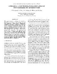
Figure 3. LISA Operation DAG<br />
implemented in its child operations. Specialized operations may be<br />
referred to by more than one parent operation. The complete structure<br />
is a Directed Acyclic Graph (DAG) D = 〈V,E〉. V represents<br />
the set of LISA operations, E the graph edges as set of child-parent<br />
relations. These relations represent activations, which refer to the<br />
execution of another LISA operation. Figure 3 gives an example of<br />
a LISA operation DAG. As shown, the operations can be distributed<br />
over several pipeline stages. A chain of operations, <strong>for</strong>ming a complete<br />
branch of the LISA operation DAG represents an instruction in<br />
the modelled processor. A LISA Operation contains different subsections<br />
to capture the entire processor behavior. The ones relevant<br />
<strong>for</strong> RTL synthesis are discussed below.<br />
Instruction Coding Description: The instruction encoding of a<br />
LISA operation is described as a sequence of coding fields. Each<br />
coding field is either a terminal bit sequence with “0”, “1”, “don’t<br />
care”(X) bits or a nonterminal bit sequence referring to the coding<br />
field of another child LISA operation.<br />
Activations: A LISA operation can activate other operations in<br />
the same or a later pipeline stage. In either case, the child operation<br />
may be activated directly or via a group. A group collects several<br />
LISA operations, with the elements being mutually exclusive. The<br />
elements are distinguished by a unique binary coding, <strong>for</strong>ming a<br />
coding tree. The activation and instruction coding tree jointly <strong>for</strong>m<br />
the decoder in the target processor. The activation chain also provides<br />
valuable in<strong>for</strong>mation regarding the dataflow in the complete<br />
processor. The activation edge is trans<strong>for</strong>med as a major steering<br />
signal in the processor datapath. For each LISA operation, a corresponding<br />
steering signal is existent. The instruction coding tree<br />
generates minor steering signals within the scope of one LISA Operation.<br />
Behavior Description: The behavior description of a LISA operation<br />
corresponds to the datapath of the processor. Inside the behavior<br />
description plain C code can be used. Resources such as registers,<br />
memories, signals and pins as well as coding elements can be<br />
accessed in the same way as ordinary variables. The behavior section<br />
of every LISA operation is trans<strong>for</strong>med into a functional block<br />
in the RTL datapath.<br />
3. Power Optimization Framework<br />
Be<strong>for</strong>e elaborating on the power-<strong>based</strong> optimization framework,<br />
a typical pipelined processor structure is explained. In the remaining<br />
part of this section, we introduce the data flow graph, which is used<br />
<strong>for</strong> operand isolation.<br />
3.1 Processor Structure<br />
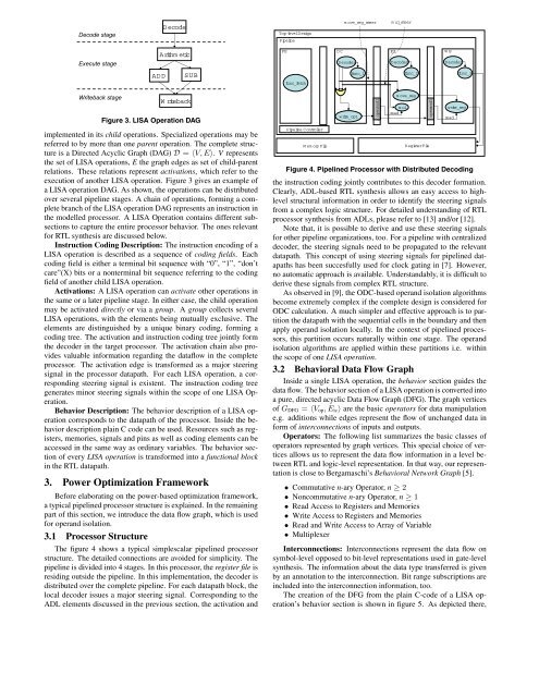
The figure 4 shows a typical simplescalar pipelined processor<br />
structure. The detailed connections are avoided <strong>for</strong> simplicity. The<br />
pipeline is divided into 4 stages. In this processor, the register file is<br />
residing outside the pipeline. In this implementation, the decoder is<br />
distributed over the complete pipeline. For each datapath block, the<br />
local decoder issues a major steering signal. Corresponding to the<br />
<strong>ADL</strong> elements discussed in the previous section, the activation and<br />
Pipeline C ontro ler<br />
MemoryFile<br />
write_op1<br />
operand1<br />
move_reg<br />
mul<br />
read<br />
RegisterFile<br />
operand1<br />
write_reg<br />
Figure 4. Pipelined Processor with Distributed Decoding<br />
the instruction coding jointly contributes to this decoder <strong>for</strong>mation.<br />
Clearly, <strong>ADL</strong>-<strong>based</strong> RTL synthesis allows an easy access to highlevel<br />
structural in<strong>for</strong>mation in order to identify the steering signals<br />
from a complex logic structure. For detailed understanding of RTL<br />
processor synthesis from <strong>ADL</strong>s, please refer to [13] and/or [12].<br />
Note that, it is possible to derive and use these steering signals<br />
<strong>for</strong> other pipeline organizations, too. For a pipeline with centralized<br />
decoder, the steering signals need to be propagated to the relevant<br />
datapath. This concept of using steering signals <strong>for</strong> pipelined datapaths<br />
has been succesfully used <strong>for</strong> clock gating in [7]. However,<br />
no automatic approach is available. Understandably, it is difficult to<br />
derive these signals from complex RTL structure.<br />
As observed in [9], the ODC-<strong>based</strong> operand isolation algorithms<br />
become extremely complex if the complete design is considered <strong>for</strong><br />
ODC calculation. A much simpler and effective approach is to partition<br />
the datapath with the sequential cells in the boundary and then<br />
apply operand isolation locally. In the context of pipelined processors,<br />
this partition occurs naturally within one stage. The operand<br />
isolation algorithms are applied within these partitions i.e. within<br />
the scope of one LISA operation.<br />
3.2 Behavioral Data Flow Graph<br />
Inside a single LISA operation, the behavior section guides the<br />
data flow. The behavior section of a LISA operation is converted into<br />
a pure, directed acyclic Data Flow Graph (DFG). The graph vertices<br />
of G DFG = 〈V op,E ic〉 are the basic operators <strong>for</strong> data manipulation<br />
e.g. additions while edges represent the flow of unchanged data in<br />
<strong>for</strong>m of interconnections of inputs and outputs.<br />
Operators: The following list summarizes the basic classes of<br />
operators represented by graph vertices. This special choice of vertices<br />
allows us to represent the data flow in<strong>for</strong>mation in a level between<br />
RTL and logic-level representation. In that way, our representation<br />
is close to Bergamaschi’s Behavioral Network Graph [5].<br />
• Commutative n-ary Operator, n ≥ 2<br />
• Noncommutative n-ary Operator, n ≥ 1<br />
• Read Access to Registers and Memories<br />
• Write Access to Registers and Memories<br />
• Read and Write Access to Array of Variable<br />
• Multiplexer<br />
Interconnections: Interconnections represent the data flow on<br />
symbol-level opposed to bit-level representations used in gate-level<br />
synthesis. The in<strong>for</strong>mation about the data type transferred is given<br />
by an annotation to the interconnection. Bit range subscriptions are<br />
included into the interconnection in<strong>for</strong>mation, too.<br />
The creation of the DFG from the plain C-code of a LISA operation’s<br />
behavior section is shown in figure 5. As depicted there,<br />
read