Hardware \in the Loop" Simulation with COSSAP: Closing the ... - ICE
Hardware \in the Loop" Simulation with COSSAP: Closing the ... - ICE
Hardware \in the Loop" Simulation with COSSAP: Closing the ... - ICE
You also want an ePaper? Increase the reach of your titles
YUMPU automatically turns print PDFs into web optimized ePapers that Google loves.
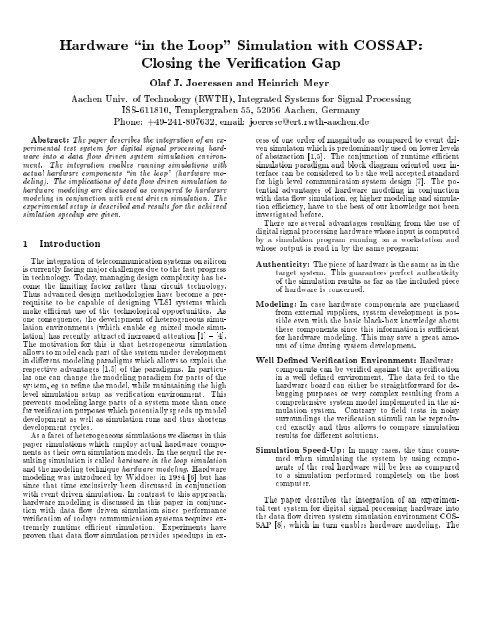
<strong>Hardware</strong> <strong>\in</strong> <strong>the</strong> Loop" <strong>Simulation</strong> <strong>with</strong> <strong>COSSAP</strong>:<br />
<strong>Closing</strong> <strong>the</strong> Verication Gap<br />
Olaf J. Joeressen and Heinrich Meyr<br />
Aachen Univ. of Technology (RWTH), Integrated Systems for Signal Processing<br />
ISS-611810, Templergraben 55, 52056 Aachen, Germany<br />
Phone: +49-241-807632, email: joeresse@ert.rwth-aachen.de<br />
Abstract: The paper describes <strong>the</strong> integration of an experimental<br />
test system for digital signal processing hardware<br />
into a data ow driven system simulation environment.<br />
The integration enables running simulations <strong>with</strong><br />
actual hardware components <strong>\in</strong> <strong>the</strong> loop" (hardware modeling).<br />
The implications of data ow driven simulation to<br />
hardware modeling are discussed ascompared tohardware<br />
modeling in conjunction <strong>with</strong> event driven simulation. The<br />
experimental setup is described and results for <strong>the</strong> achieved<br />
simlation speedup are given.<br />
1 Introduction<br />
The integration of telecommunication systems on silicon<br />
is currently facing major challenges due to <strong>the</strong> fast progress<br />
in technology. Today, managing design complexityhasbecome<br />
<strong>the</strong> limiting factor ra<strong>the</strong>r than circuit technology.<br />
Thus advanced design methodologies have become a prerequisite<br />
to be capable of designing VLSI systems which<br />
make ecient use of <strong>the</strong> technological opportunities. As<br />
one consequence, <strong>the</strong> development of heterogeneous simulation<br />
environments (which enable eg mixed mode simulation)<br />
has recently attracted increased attention [1] { [4].<br />
The motivation for this is that heterogeneous simulation<br />
allows to model each part of <strong>the</strong> system under development<br />
in dierent modeling paradigms whichallows to exploit <strong>the</strong><br />
respective advantages [1,5] of <strong>the</strong> paradigms. In particular<br />
one can change <strong>the</strong> modeling paradigm for parts of <strong>the</strong><br />
system, eg to rene <strong>the</strong> model, while maintaining <strong>the</strong> high<br />
level simulation setup as verication environment. This<br />
prevents modeling large parts of a system more than once<br />
for verication purposes which potentially speeds up model<br />
development aswell as simulation runs and thus shortens<br />
development cycles.<br />
As a facet of heterogeneous simulations we discuss in this<br />
paper simulations which employ actual hardware components<br />
as <strong>the</strong>ir own simulation models. In <strong>the</strong> sequel <strong>the</strong> resulting<br />
simulation is called hardware in <strong>the</strong> loop simulation<br />
and <strong>the</strong> modeling technique hardware modeling. <strong>Hardware</strong><br />
modeling was introduced by Widdoes in 1984 [6] buthas<br />
since that time exclusively been discussed in conjunction<br />
<strong>with</strong> event driven simulation. In contrast to this approach,<br />
hardware modeling is discussed in this paper in conjunction<br />
<strong>with</strong> data ow driven simulation since performance<br />
verication of todays communication systems requires extremely<br />
runtime ecient simulation. Experiments have<br />
proven that data ow simulation provides speedups in excess<br />
of one order of magnitude as compared to event driven<br />
simulaton which is predominantly used on lower levels<br />
of abstraction [1,5]. The conjunction of runtime ecient<br />
simulation paradigm and block diagram oriented user interface<br />
can be considered to be <strong>the</strong> well accepted standard<br />
for high level communication system design [7]. The potential<br />
advantages of hardware modeling in conjunction<br />
<strong>with</strong> data ow simulation, eg higher modeling and simulation<br />
eciency, have to<strong>the</strong>bestofourknowledge not been<br />
investigated before.<br />
There are several advantages resulting from <strong>the</strong> use of<br />
digital signal processing hardware whose input is computed<br />
by asimulation program running on a workstation and<br />
whose output is read in by <strong>the</strong> same program:<br />
Au<strong>the</strong>nticity: The piece of hardware is <strong>the</strong> same as in <strong>the</strong><br />
target system. This guarantees perfect au<strong>the</strong>nticity<br />
of <strong>the</strong> simulation results as far as <strong>the</strong> included piece<br />
of hardware is concerned.<br />
Modeling: In case hardware components are purchased<br />
from external suppliers, system development ispossible<br />
even <strong>with</strong> <strong>the</strong> basic black-box knowledge about<br />
<strong>the</strong>se components since this information is sucient<br />
for hardware modeling. This may save a great amount<br />
of time during system development.<br />
WellDenedVerication Environment: <strong>Hardware</strong><br />
components can be veried against <strong>the</strong> specication<br />
inawell dened environment. The data fed to <strong>the</strong><br />
hardware board can ei<strong>the</strong>r be straightforward for debugging<br />
purposes or very complex resulting from a<br />
comprehensive system model implemented in <strong>the</strong> simulation<br />
system. Contrary to eld tests in noisy<br />
surroundings <strong>the</strong> verication stimuli can be reproduced<br />
exactly and thus allows to compare simulation<br />
results for dierent solutions.<br />
<strong>Simulation</strong> Speed-Up: In many cases, <strong>the</strong> time consumed<br />
when simulating <strong>the</strong> system by using components<br />
of <strong>the</strong> real hardware will be less as compared<br />
to a simulation performed completely on <strong>the</strong> host<br />
computer.<br />
The paper describes <strong>the</strong> integration of an experimental<br />
test system for digital signal processing hardware into<br />
<strong>the</strong> data ow driven system simulation environment COS-<br />
SAP [8], which in turn enables hardware modeling. The
implications and restrictions of data ow driven simulations<br />
in conjunction <strong>with</strong> hardware modeling are discussed.<br />
The advantages are claried as compared to hardware<br />
modeling in conjunction <strong>with</strong> event driven simulaton,<br />
which is already supported by commercially available<br />
products [9,10].<br />
S<br />
Clock<br />
Event<br />
Time<br />
2 <strong>Hardware</strong> Modeling and Data Flow <strong>Simulation</strong><br />
We will briey introduce <strong>the</strong> concept of a signal in a<br />
data ow driven simulation in this section to prepare <strong>the</strong><br />
ground for a clear discussion of advantages and limitations<br />
of hardware modeling in <strong>the</strong> context of a data ow driven<br />
simulation.<br />
2.1 Signal Paradigms<br />
<strong>Hardware</strong> modeling requires <strong>the</strong> generation of all physical<br />
signals that are required to run <strong>the</strong> hardware controlled<br />
by <strong>the</strong> simulation. Thus <strong>the</strong> clear understanding of <strong>the</strong><br />
meaning of a signal in <strong>the</strong> simulation (<strong>the</strong> signal paradigm)<br />
is a prerequisite for <strong>the</strong> integration of hardware in <strong>the</strong> loop.<br />
A signal paradigm denes<br />
<strong>the</strong> relation of <strong>the</strong> value of a signal to <strong>the</strong> ongoing<br />
(virtual) simulation time.<br />
at which time a simulation model is red to compute<br />
new values of its output signals (module scheduling).<br />
Dierent signal paradigms reect dierent levels of abstraction<br />
of a physical signal which exhibit a value at every<br />
point of time and is thus not generally representable in a<br />
digital computer. In digital system design two important<br />
paradigms are <strong>the</strong> event driven [11] and data ow driven<br />
signal paradigms [12,1]. Table 1 lists <strong>the</strong> basic properties<br />
of <strong>the</strong>se signal paradigms.<br />
Tab. 1: Signal Paradigms<br />
signal signal/time scheduling used<br />
paradigm relation scheme in<br />
event value & time change of an VHDL<br />
driven of change input signal etc.<br />
data ow only sequence all necessary input <strong>COSSAP</strong><br />
driven of values samples available etc.<br />
Event driven simulations are based on <strong>the</strong> idea that<br />
a signal can be described by a sequence of events which<br />
describe a signal change. The event isthus characterized<br />
by<strong>the</strong>newvalue of <strong>the</strong> related signal and <strong>the</strong> time at which<br />
<strong>the</strong> change occurs. A model needs to be red only when an<br />
input signal is changed by suchanevent. The red model<br />
<strong>the</strong>n computes <strong>the</strong> new values of its output signals. The<br />
associated events are inserted into an event table which is<br />
managed by <strong>the</strong> kernel of <strong>the</strong> simulator.<br />
Event driven simulations allow tosimulate circuit behavior<br />
precise enough for chip sign o, including eg analysis<br />
of setup and hold times. On <strong>the</strong> o<strong>the</strong>r hand <strong>the</strong> nature<br />
of <strong>the</strong> paradigm requires that all control signals like clock<br />
Time<br />
Fig. 1: Event driven signal representation<br />
and reset in synchronous designs are explicit since only<br />
<strong>the</strong> association of clock edges and signal values allow to<br />
determine what <strong>the</strong> meaningful data <strong>with</strong> respect to <strong>the</strong><br />
implemented chip function is (see Figure 1).<br />
Data ow simulations, in contrast, do not keep track<br />
of <strong>the</strong> time. Signal are represented merely by sequences<br />
of values. The sequence does not even necessarily have an<br />
interpretation on <strong>the</strong> time axis. The values may equally<br />
well describe for example signals in <strong>the</strong> frequency domain<br />
or asynchronous signals [13]. The models are executed<br />
if all required input values for executing <strong>the</strong> model are<br />
present in <strong>the</strong> input signal buers. The model <strong>the</strong>n computes<br />
output values based on its inputs and places <strong>the</strong>m<br />
in output buers. The simulator consequently does not<br />
handle time. The number of items in signal buers and<br />
<strong>the</strong> information about <strong>the</strong> required number of input values<br />
to execute a model is sucient to execute <strong>the</strong> simulation.<br />
This completely dierent signal paradigm leads to signicant<br />
simulation speedups and provides increased modeling<br />
exibility.<br />
S<br />
Fig. 2: Data ow signal representation<br />
n<br />
Sequence of values<br />
No Time !<br />
In contrast to event driven simulation control signals are<br />
not required to model systems in a data owdriven simulation<br />
since <strong>the</strong> sequence of values is sucient todrivemost<br />
algorithms in digital signal processing. However, whenever<br />
interfacing to real world signals is required an interpretation<br />
over time must be added to <strong>the</strong> data ow signals.<br />
Fur<strong>the</strong>rmore, data ow signals are always generated at a<br />
single source and thus represent unidirectional data ow.<br />
This leads to problems if bidirectional signals or busses are<br />
to be interfaced and would required to represent a bidirectional<br />
signal by three data ow signals (in, out, direction).<br />
We do not discuss interfacing to bidirectional signals in<br />
this report.<br />
2.2 Interfacing to Physical Signals<br />
Physical signals are obviously not directly interfaceable<br />
to a data ow signal since <strong>the</strong>y continuously exhibit a value
at each time instant. Consequently sampling of <strong>the</strong>se signals<br />
is required to interface to <strong>the</strong> simulation. This poses<br />
<strong>the</strong> problem of dening or determining what <strong>the</strong> meaningful<br />
sampling time instants are.<br />
In <strong>the</strong> case of an analog hardware this leads immediately<br />
to real time requirements, appropriate ltering of <strong>the</strong><br />
input data, analog to digital and digital to analog conversion.<br />
Fur<strong>the</strong>rmore buering of <strong>the</strong> digital input and<br />
output signals in FIFOs is required to maintain for example<br />
an equidistant sampling since <strong>the</strong> simulation program<br />
will usually not be able to consume and produce <strong>the</strong> data<br />
at absolute time instants.<br />
Digital hardware usually ei<strong>the</strong>r runs at a xed clock rate<br />
which in turn denes at what time meaningful signal values<br />
at <strong>the</strong> ports are present or establishes explicit handshaking<br />
schemes. Asynchronous interface schemes may require <strong>the</strong><br />
data to be set up in frames <strong>with</strong> clearly dened timing of<br />
<strong>the</strong> data items. However, this timing scheme is usually<br />
dened relative toasystemclock. Consequently, most<br />
interface schemes can be handled <strong>with</strong>out absolute signal<br />
timing at <strong>the</strong> interfaces provided that clock and control<br />
signals are under <strong>the</strong> control of <strong>the</strong> simulation program.<br />
Exceptions are all systems which have internal clock<br />
sources, completely asynchronous components or systems<br />
which contain dynamic storage which loose <strong>the</strong>ir content<br />
if <strong>the</strong> operating speed is below a certain limit. Such devices<br />
can be handled ei<strong>the</strong>r if realtime constraints are met<br />
as discussed above orby means of running an appropriate<br />
stimuli history every time a new output value is to be determined<br />
[14]. As a advantage of <strong>the</strong> latter case multiple<br />
instances of <strong>the</strong> device in a simulation can be handled if<br />
<strong>the</strong> stimuli history is stored for each instance. Clearly,supporting<br />
dynamic components and multiple instances leads<br />
to very complex interfaces <strong>with</strong> high speed memory, programmable<br />
clock sources etc. . However, an important<br />
disadvantage of <strong>the</strong> approach is that <strong>the</strong> length of <strong>the</strong> stimuli<br />
history is naturally limited which was not acceptable<br />
in our case since we wanted to run very long performance<br />
simulations.<br />
2.3 Interface Model Requirements<br />
It is of course desirable to provide a hardware model at<br />
<strong>the</strong> system level to <strong>the</strong> design engineer which resembles<br />
<strong>the</strong> hardware in a form that allows easy integration into<br />
<strong>the</strong> system simulation setup. At best, <strong>the</strong> model interface<br />
would resemble that of a standard simulation model of<br />
similar functionality.<br />
A primitive model 1 in <strong>COSSAP</strong> is a model written in a<br />
programming language likeCwhich communicates via well<br />
dened interface functions to o<strong>the</strong>r models. There are no<br />
restrictions on what a primitive model may compute. Consequently,<br />
<strong>the</strong> natural way tointegrate a facility for hardware<br />
modeling in <strong>COSSAP</strong> is via a primitive model which<br />
is tailored to steer a specic hardware interface, this model<br />
is called <strong>the</strong> interface model in <strong>the</strong> sequel. The hardware<br />
interface should be as versatile as possible and capable of<br />
steering various hardware components. We consider <strong>the</strong><br />
1 The o<strong>the</strong>r kind of models which can be specied are <strong>the</strong> so called<br />
hierarchical models which <strong>the</strong>mself maycontain o<strong>the</strong>r hierarchical<br />
models and primitive models. These modeling styles are in o<strong>the</strong>r contexts<br />
usually denoted as behavioral and structural model respectively.<br />
hardware interface for <strong>the</strong> discussion of <strong>the</strong> interface model<br />
to be a simple parallel interface <strong>with</strong> N pins. Each<br />
pin of <strong>the</strong> interface can be programmed as input or output<br />
signal.<br />
An obvious modeling possibility for <strong>the</strong> interface model<br />
is of course a model <strong>with</strong> N inputs and outputs and<br />
appropriate interface direction parameters. However, such<br />
amodulewould be very cumbersome to use since explicit<br />
mapping of data ow values to single interface bits would<br />
be required. This would require <strong>the</strong> use of additional models<br />
and would probably result in complex hierarchical models.<br />
In order to be easy and convenient to use, <strong>the</strong> interface<br />
model should comprise <strong>the</strong> following functionality :<br />
Universality: The interface model should be parameterizable<br />
to serve arbitrary hardware hooked on <strong>the</strong><br />
hardware interface.<br />
Initialization: The interface model should provide a possibility<br />
to initialize <strong>the</strong> hardware and <strong>the</strong> hardware<br />
interface, since explicit signal generation for initialization<br />
in <strong>the</strong> simulation setup can be very awkward.<br />
Signal Hiding: The interface model should be capable of<br />
applying simple clock systems, and constant signal<br />
values to <strong>the</strong> hardware <strong>with</strong>out requiring equivalent<br />
data ow signals, since <strong>the</strong>se signals are often not<br />
required for <strong>the</strong> remaining simulation.<br />
Signal Mapping: The interface model should interface<br />
directly to data ow signals, and perform a mapping<br />
of <strong>the</strong>se signals to <strong>the</strong> wires of <strong>the</strong> hardware interface.<br />
This is referred to as signal mapping in <strong>the</strong> sequel and<br />
avoids to explicitly map a bit interpretation of a data<br />
ow signal to single bits at <strong>the</strong> hardware interface by<br />
means of o<strong>the</strong>r primitive models.<br />
Generating clock signals of course implies that <strong>the</strong> hardware<br />
hooked upon <strong>the</strong> hardware interface is clocked synchronous<br />
hardware <strong>with</strong> static storage elements, but a<br />
capability to hide any type of hardware control signals<br />
would be very dicult to implement and <strong>the</strong> general specication<br />
of such control signals is as well dicult.<br />
To be able to perform a correct signal mapping, an interpretation<br />
of numeric data ow signals in terms of an equivalent<br />
bit vector representation must be specied. This<br />
may comprise simple mappings of <strong>the</strong> internal representation<br />
of <strong>the</strong> host computer to bits at <strong>the</strong> hardware interface<br />
(which maybemachine dependent), but for output<br />
signals it would be convenient to be able to specify interpretations,<br />
eg whe<strong>the</strong>r a hardware signal is to be interpreted<br />
as a sign bit.<br />
3 Asample Solution<br />
We developed a primitive model for <strong>the</strong> system simulator<br />
<strong>COSSAP</strong> and a proprietary hardware interface at our<br />
institute which allows us to model hardware mainly for<br />
systems and ASICs developed in our institute.
<strong>COSSAP</strong><br />
<strong>COSSAP</strong><br />
3.1 ISS Test{<strong>Hardware</strong><br />
As was elaborated in section 2.2, <strong>the</strong> complexity of<strong>the</strong><br />
interface hardware is determined to a large degree by <strong>the</strong><br />
hardware which is to be included into <strong>the</strong> simulation setup.<br />
The interface complexitymay range from simple programmable<br />
parallel interface to complex hardware which<br />
may be required to satisfy absolute timing requirements.<br />
E<strong>the</strong>rnet<br />
Host Computer<br />
ISS-Testsystem<br />
congured to be interpreted as positive binary numbers or<br />
signedintwo's complement representation. Figure 4 shows<br />
<strong>the</strong> principal functionality of <strong>the</strong> model.<br />
In-Ports<br />
Configuration Data: Mapping, Clock Speed, ..<br />
Inputs Constants Clocking Outputs<br />
Mapping<br />
.<br />
.<br />
.<br />
.<br />
.<br />
Mapping<br />
Pins<br />
Device<br />
Adaptor<br />
Pins<br />
.<br />
.<br />
Mapping<br />
Out-Ports<br />
Host Interface<br />
Versatile <strong>COSSAP</strong> Module + Interface +<br />
Fig. 3: ISS Test <strong>Hardware</strong><br />
Device Adaptor<br />
Device under Test<br />
Standard Test Environment<br />
The test hardware at our institute was developed for low<br />
cost testing of fully synchronous digital hardware. The test<br />
hardware consists of 160 programmable interface pins, a<br />
programmable clock generator which provides three clock<br />
signals of up to 50MHz frequency and a programmable cycle<br />
counter which allows to apply clock bursts of up to 2 24<br />
cycles to <strong>the</strong> device under test. During clock bursts nei<strong>the</strong>r<br />
changing input signals is possible nor reading output signals.<br />
Each device under test is tted <strong>with</strong> a unique device<br />
adaptor to <strong>the</strong> test hardware, clock andpower is hardwired<br />
this way which greatly reduces complexity of <strong>the</strong> test<br />
hardware. The test hardware is steered by a simple interface<br />
in <strong>the</strong> host computer. Figure 3 gives an overview<br />
of <strong>the</strong> complete setup. Fur<strong>the</strong>rmore a program which is<br />
capable of running stimuli in a proprietary format on <strong>the</strong><br />
hardware interface was developed. This capability isused<br />
for automatic testing and initialization of <strong>the</strong> hardware<br />
during <strong>the</strong> initialization phase of a simulation. There are<br />
no FIFOs attached to <strong>the</strong> pins and <strong>the</strong> hardware interface<br />
can <strong>the</strong>refore not satisfy absolute timing constraints.<br />
However, tests at full speed are possible if <strong>the</strong> attached<br />
hardware does not require input signal changes during <strong>the</strong><br />
test. This is often <strong>the</strong> case if ASICs contain circuitry for<br />
built in self test [15]. The boards and ASICs developed in<br />
our laboratory are indeed tested at full speed during <strong>the</strong><br />
initialization phase.<br />
3.2 AVersatile Interface Model<br />
Aversatile <strong>COSSAP</strong> module has been developed which<br />
is congurable for any device adaptor. The module takes<br />
a data set for module conguration [16]. <strong>Hardware</strong> initialization<br />
is performed in <strong>the</strong> aforementioned manner. The<br />
model is capable of applying constants and simple clock<br />
systems. The data ow signals which are connected to<br />
<strong>the</strong> model must be of type integer, output signals can be<br />
HiSL_cossapsoft.id<br />
ISS-<br />
Testsystem<br />
Initialization Data:<br />
Reset, Initial Test, ..<br />
Fig. 4: Structure of <strong>the</strong> <strong>COSSAP</strong> Module<br />
The data set which congures <strong>the</strong> model has four parts<br />
which establish input mapping, output mapping and interpretation,<br />
constant signal specication and clock specication.<br />
A mapping specication establishes a mapping<br />
between a data ow signal (of type integer) at port number<br />
N to one or more bits of <strong>the</strong> hardware interface. The<br />
number of module ports is not xed and <strong>the</strong> ports consequently<br />
have no names. They are identied by a unique<br />
port number which represents <strong>the</strong> sequence in which signals<br />
were connected to <strong>the</strong> model. This is <strong>the</strong> number<br />
which is referred to in <strong>the</strong> data set. The interpretation<br />
of <strong>the</strong> mapping records begins <strong>with</strong> <strong>the</strong> least signicant<br />
bit (LSB) and proceeds towards <strong>the</strong> most signicant bit<br />
(MSB) if more than one record establishes <strong>the</strong> mapping.<br />
A sample mapping and its specication records for input<br />
ports is shown in Figure 5.<br />
This approach allows arbitrary mappings in a concise<br />
form to be specied, since we do not need to map every<br />
single bit by a separate data set entry as long as <strong>the</strong>y are<br />
to be mapped on sequential pins of <strong>the</strong> hardware interface.<br />
At <strong>the</strong> output side of <strong>the</strong> model an additional entry in <strong>the</strong><br />
data set species whe<strong>the</strong>r a signed or unsigned representation<br />
is to be assumed. Clock specication is done <strong>with</strong><br />
<strong>the</strong> parameters frequency, phase, duty cycle and cycles per<br />
sample. The parameter cycles per sample allows to interface<br />
eciently to hardware which exchanges only every N<br />
clock cycles meaningful data. Since we can not guarantee<br />
absolute timing at <strong>the</strong> hardware, <strong>the</strong> clock specication is<br />
interpreted in our case more or less as a sequence of signal<br />
changes ra<strong>the</strong>r than running a clock system <strong>with</strong> <strong>the</strong><br />
specied timing between sampling <strong>the</strong> hardware signals.<br />
3.3 Performance<br />
In many cases, <strong>the</strong> time consumed when simulating <strong>the</strong><br />
system by using components of <strong>the</strong> real hardware will be<br />
less as compared to a simulation performed completely on<br />
<strong>the</strong> host computer. Overhead is introduced mainly for
Interface Model<br />
IS2 - Interface <strong>Hardware</strong><br />
LSB 0<br />
3<br />
Inport 1<br />
1<br />
2<br />
10<br />
11<br />
1<br />
2<br />
1 1<br />
Data Flow Signals<br />
LSB<br />
0<br />
1<br />
LSB 0<br />
15<br />
inmap_example.id<br />
Inport 2<br />
Inport 3<br />
3<br />
4<br />
5<br />
8<br />
18<br />
12<br />
21<br />
26<br />
Data Record Sequence<br />
Input Port-Number<br />
First Sequential Pin<br />
Last Sequential Pin<br />
3<br />
4<br />
5<br />
6<br />
1<br />
1<br />
2<br />
5<br />
10<br />
15<br />
20<br />
25<br />
26 26<br />
1 2<br />
10 3<br />
11 4<br />
Pins<br />
1 2 3 4 5 6<br />
3 3 3<br />
5 17 21<br />
8 12 26<br />
Fig. 5: Input mapping example<br />
Device<br />
transferring data between host and hardware and for mapping<br />
signals of <strong>the</strong> simulator to actual hardware pins.<br />
In <strong>the</strong> following we discuss as an example <strong>the</strong> simulation<br />
of <strong>the</strong> experimental fully digital 100MBit/s receiver DI-<br />
RECS [13], which consists of 6 ASICs. Figure 6 shows <strong>the</strong><br />
hierarchical software model of <strong>the</strong> receiver which consists<br />
of several primitive models. These models reproduce exactly<br />
<strong>the</strong> behavior of <strong>the</strong> chip set and consume over 92% of<br />
<strong>the</strong> simulation runtime in conjunction <strong>with</strong> a simple noisy<br />
channel and <strong>the</strong> appropriate signal source.<br />
Fig. 7: <strong>COSSAP</strong> <strong>Hardware</strong> Model of DIRECS<br />
complex component <strong>the</strong> rst step is eightfold serial to parallel<br />
conversion in <strong>the</strong> module S2PI. The system clock is<br />
generated in <strong>the</strong> block THW_LOOP thus no explicit clock signal<br />
is required in <strong>the</strong> model of Figure 7. A constant signal<br />
is applied <strong>with</strong> a data set entry while o<strong>the</strong>rs were fed<br />
into <strong>the</strong> hardware through <strong>the</strong> constant sources CONSTI because<br />
<strong>the</strong>ir values were frequently changed. They could be<br />
parameterized at <strong>the</strong> top level simulation setup this way.<br />
Figure 7 shows several additional outputs of <strong>the</strong> receiver<br />
board which allow observation of some internal signals.<br />
By runtime proling of our software, it was found that<br />
<strong>the</strong> bandwidth of <strong>the</strong> host interface limits <strong>the</strong> simulation<br />
throughput of our example. However, even in <strong>the</strong> small<br />
simulation setup described above, <strong>the</strong> interface software<br />
to our testing environment consumed only 20% of <strong>the</strong> simulation<br />
runtime which shows that optimization of this<br />
interface would not result in large speedups. After all, <strong>the</strong><br />
verication of <strong>the</strong> receiver was made possible down to bit<br />
error rates of 10 ;7 due to a tenfold increase in simulation<br />
eciency as compared to <strong>the</strong> software models of Figure 6.<br />
The resulting number of 250 million clock cycles (17 Gigabits<br />
of data) shows clearly why playing stimuli historys<br />
was not a viable solution for our application. A clock cycle<br />
on <strong>the</strong> hardware <strong>with</strong> 93 bits interfacing takes 400s on a<br />
SPARC Server 4/330.<br />
Fig. 6: Hierarchical <strong>COSSAP</strong> Model of DIRECS<br />
It is worth mentioning here that <strong>the</strong> model in Figures<br />
6 has dierent data rates at inputs and outputs since a<br />
digital receiver usually requires oversampling of <strong>the</strong> input<br />
signals. In <strong>the</strong> case of DIRECS, fourfold oversampling toge<strong>the</strong>r<br />
<strong>with</strong> certain properties of <strong>the</strong> employed transmission<br />
scheme lead to an eightfold rate reduction from inputs<br />
to outputs. In real hardware, parallel processing was required<br />
to achieve <strong>the</strong> extreme data rate and eight input<br />
samples are processed in parallel. The hardware model<br />
thus comprises some additional software blocks. Figure 7<br />
shows <strong>the</strong> <strong>COSSAP</strong> conguration for <strong>the</strong> hardware model.<br />
The block THW_LOOP is <strong>the</strong> versatile interface model .<br />
Since <strong>the</strong> hardware has eight parallel inputs for each<br />
4 Commercial Solutions<br />
To <strong>the</strong> best of our knowledge hardware modelers are<br />
available from Logic Modeling Inc. only [9] { [17]. They<br />
have beendevelopedtowork well in <strong>the</strong> event driven context<br />
but integration intoadataowcontext would be possible<br />
as well. While data ow simulations do not need timing<br />
information, event driven simulations do (see section<br />
2.1). In commercial hardware modelers timing is added in<br />
software by means of timing models ra<strong>the</strong>r than by measuring<br />
<strong>the</strong> response of <strong>the</strong> device which would require much<br />
more costly interface hardware. Thus <strong>the</strong> accuracy of <strong>the</strong><br />
timing model underlies <strong>the</strong> same restrictions as in standard<br />
software models. In commercial hardware modelers
chips are tted on standard device adaptors ra<strong>the</strong>r than<br />
device specic ones, which are needed in our case. This<br />
increases <strong>the</strong> interface complexity sincepower and ground<br />
pins need to be congurable, but eases <strong>the</strong> setup. However,<br />
for complete systems ra<strong>the</strong>r than single chips special<br />
device adaptors are still required. The hardware modelers<br />
can handle bidirectional as well as unidirectional device<br />
ports. They are stand alone e<strong>the</strong>rnet devices and some<br />
communication overhead is <strong>the</strong> price for obtaining a hardware<br />
modeler which is independent of <strong>the</strong> simulation workstation<br />
architecture. Current product information led to<br />
<strong>the</strong> estimate that no simulation speedup would have been<br />
possible in <strong>the</strong> simulation of DIRECS. Current pricing for<br />
hardware modelers is well above US$ 100.000 and development<br />
kits to integrate <strong>the</strong> hardware modelers into existing<br />
simulation environments are very expensive too.<br />
5 Conclusion<br />
While hardware modeling in copnjunction <strong>with</strong> eventdriven<br />
simulation is a commercial reality, our experimental<br />
setup shows that hardware modeling is possible in conjunction<br />
<strong>with</strong> data ow driven simulations. This is due to<br />
<strong>the</strong> fact that we deal <strong>with</strong> <strong>the</strong> sequence of meaningful values<br />
ra<strong>the</strong>r than timed signals. Fur<strong>the</strong>rmore, <strong>the</strong> class of<br />
hardware components which can be handled was restricted<br />
to fully synchronous components <strong>with</strong> static memory<br />
to avoid recording and playing stimuli historys. We did<br />
not support bidirectional ports. These restrictions reect<br />
our application domain which is in <strong>the</strong> loop simulation<br />
of digital signal processing ASICs for performance verication.<br />
An experimental hardware modeling solution for<br />
<strong>the</strong> simulation system <strong>COSSAP</strong> was developed in conjunction<br />
<strong>with</strong> a proprietary test environment forintegrated<br />
circuits and VLSI systems. This solution provides <strong>the</strong> full<br />
functionality for hardware modeling of <strong>the</strong> envisaged class<br />
of hardware components at high simulation speed and low<br />
cost. It turned out during runtime proling that in our implementation<br />
<strong>the</strong> small wordlength of <strong>the</strong> hostinterface is<br />
<strong>the</strong> remaining bottleneck but <strong>the</strong> interface model provides<br />
already a throughput at which simple additional software<br />
models are <strong>the</strong> speed limiting factor.<br />
Bibliography<br />
[1] P. Zepter and K. ten Hagen, \Using VHDL <strong>with</strong> stream<br />
driven simulators for digital signal processing applications,"<br />
in EURO-VHDL'91 Proceedings, (Stockholm, Sweden),<br />
pp. 196{203, September 8-11 1991.<br />
[2] J. Buck, S. Ha, E. A. Lee, and D. G. Messerschmitt, \Ptolemy:<br />
A platform for heterogenous simulation and prototyping,"<br />
in Proc. 1991 European <strong>Simulation</strong> Conf., (Copenhagen,<br />
Denmark), June 1991.<br />
[3] M. Pankert, S. Ritz, and H. Meyr, \Integration of digital<br />
signal processing hardware into a system level simulation<br />
environment," in European <strong>Simulation</strong> Multiconference,<br />
(York, United Kingdom), pp. 394{398, SCS International,<br />
1992.<br />
[4] \Simbus simulation backplane." Product Information, ViewLogic<br />
Inc., 1993.<br />
[5] G. Jennings, \A case against event driven simulation of<br />
digital system design," in The 24th Annual <strong>Simulation</strong><br />
Symposium (A. H. Rutan, ed.), (Los Alamitos, California),<br />
pp. 170{176, IEEE Computer Society Press, April 1991.<br />
[6] L. Widdoes and W. Harding, \CAE station uses real<br />
chips to simulate VLSI-based systems," Electronic Design,<br />
vol. 32, pp. 167{76, March 1984.<br />
[7] K. S. Shanmugan, \An update on software packages for simulation<br />
of communication systems (Links)," IEEE JournalonSel.Areas<br />
in Commun., vol. 6, pp. 5{12, January<br />
1988.<br />
[8] J. Kunkel, \<strong>COSSAP</strong>: A stream driven simulator," in<br />
IEEE International Workshop on Microelectronics in<br />
Communications, Interlaken, Switzerland, March 1991.<br />
[9] M. Donlin, \Accurate device models makes PCB simulation<br />
a reality," Computer Design, pp. 71{76, July 1991.<br />
Penn Well Publishing Co.<br />
[10] N. Kelly and H. Stump, \Software architecture of universal<br />
hardware modeler," in Proceedings of <strong>the</strong> European Design<br />
Automation Conference, (Glasgow, UK), pp. 573{7,<br />
IEEE/EDAC, March 1990.<br />
[11] R. M. Fujimoto, \Parallel Discrete Event <strong>Simulation</strong>,"<br />
Communications of <strong>the</strong> ACM, vol. 33, pp. 31{53, Oct.<br />
1990. 98 ref.<br />
[12] E. A. Lee and D. G. Messerschmitt, \Synchronous data<br />
ow," Proceedings of <strong>the</strong> IEEE, vol. 75, pp. 1235{1245,<br />
September 1987.<br />
[13] O. J. Joeressen, M. Oerder, R. Serra, and H. Meyr, \DI-<br />
RECS: System design of a 100Mbit/s digital receiver," IEE<br />
Proceedings-G,vol. 139, pp. 222{230, April 1992.<br />
[14] L. Widdoes and H. Stump, \<strong>Hardware</strong> modeling," VLSI<br />
Systems Design, vol. 9, pp. 30{8, July 1988.<br />
[15] R. Serra and H. Meyr, \Geschwindigkeitsoptimierter Systemselbsttest<br />
fur schnelle digitale Schaltkreise," in GME-<br />
Fachbericht 8, (Baden-Baden), pp. 253{258, vde-verlag,<br />
Berlin Oenbach, March, 4.-6. 1991.<br />
[16] <strong>COSSAP</strong> Manual, Volume 1-5, Synopsys Inc., Herzogenrath,<br />
Germany.<br />
[17] H. Stump, \<strong>Hardware</strong>modellierung { ein wesentlicher Bestandteil<br />
der Systemsimulation," Elektronik, no. 21, 1990.<br />
Franzis Verlag, Munchen, (in german).<br />
[18] D. Giles, K. Bowden, M. Haney, and G. Maston, \Maintaining<br />
simulation accuracy through physical device models,"<br />
in Proceedings of <strong>the</strong> International Test Conference 1985,<br />
(Philadelphia, PA), pp. 692{695, IEEE, Nov 1985.<br />
[19] A. Read and H. Stump, \<strong>Hardware</strong> modeling in ASIC prototype<br />
verication," in ATE and Instrumentation Conference<br />
West, (Anaheim, CA), pp. 76{81, Jan 1989.<br />
[20] H. Stump, \A designer's guide to simulation models,"<br />
Computer Design, vol. 29, pp. 91{2, Jan 1990.<br />
[21] U. Dersch and P. Rauber, \Modellierung und <strong>Simulation</strong><br />
des Mobilfunkkanals," ASCOM Technische Mitteilungen,<br />
no. 2, pp. 9{14, 1991. (in german).


