Hardware \in the Loop" Simulation with COSSAP: Closing the ... - ICE
Hardware \in the Loop" Simulation with COSSAP: Closing the ... - ICE
Hardware \in the Loop" Simulation with COSSAP: Closing the ... - ICE

You also want an ePaper? Increase the reach of your titles
YUMPU automatically turns print PDFs into web optimized ePapers that Google loves.
<strong>COSSAP</strong><br />
<strong>COSSAP</strong><br />
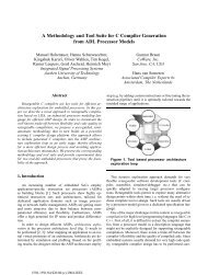
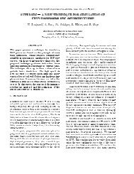
3.1 ISS Test{<strong>Hardware</strong><br />
As was elaborated in section 2.2, <strong>the</strong> complexity of<strong>the</strong><br />
interface hardware is determined to a large degree by <strong>the</strong><br />
hardware which is to be included into <strong>the</strong> simulation setup.<br />
The interface complexitymay range from simple programmable<br />
parallel interface to complex hardware which<br />
may be required to satisfy absolute timing requirements.<br />
E<strong>the</strong>rnet<br />
Host Computer<br />
ISS-Testsystem<br />
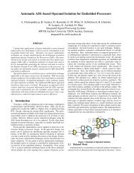
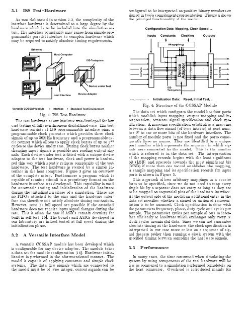
congured to be interpreted as positive binary numbers or<br />
signedintwo's complement representation. Figure 4 shows<br />
<strong>the</strong> principal functionality of <strong>the</strong> model.<br />
In-Ports<br />
Configuration Data: Mapping, Clock Speed, ..<br />
Inputs Constants Clocking Outputs<br />
Mapping<br />
.<br />
.<br />
.<br />
.<br />
.<br />
Mapping<br />
Pins<br />
Device<br />
Adaptor<br />
Pins<br />
.<br />
.<br />
Mapping<br />
Out-Ports<br />
Host Interface<br />
Versatile <strong>COSSAP</strong> Module + Interface +<br />
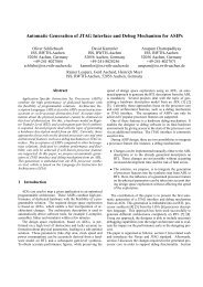
Fig. 3: ISS Test <strong>Hardware</strong><br />
Device Adaptor<br />
Device under Test<br />
Standard Test Environment<br />
The test hardware at our institute was developed for low<br />
cost testing of fully synchronous digital hardware. The test<br />
hardware consists of 160 programmable interface pins, a<br />
programmable clock generator which provides three clock<br />
signals of up to 50MHz frequency and a programmable cycle<br />
counter which allows to apply clock bursts of up to 2 24<br />
cycles to <strong>the</strong> device under test. During clock bursts nei<strong>the</strong>r<br />
changing input signals is possible nor reading output signals.<br />
Each device under test is tted <strong>with</strong> a unique device<br />
adaptor to <strong>the</strong> test hardware, clock andpower is hardwired<br />
this way which greatly reduces complexity of <strong>the</strong> test<br />
hardware. The test hardware is steered by a simple interface<br />
in <strong>the</strong> host computer. Figure 3 gives an overview<br />
of <strong>the</strong> complete setup. Fur<strong>the</strong>rmore a program which is<br />
capable of running stimuli in a proprietary format on <strong>the</strong><br />
hardware interface was developed. This capability isused<br />
for automatic testing and initialization of <strong>the</strong> hardware<br />
during <strong>the</strong> initialization phase of a simulation. There are<br />
no FIFOs attached to <strong>the</strong> pins and <strong>the</strong> hardware interface<br />
can <strong>the</strong>refore not satisfy absolute timing constraints.<br />
However, tests at full speed are possible if <strong>the</strong> attached<br />
hardware does not require input signal changes during <strong>the</strong><br />
test. This is often <strong>the</strong> case if ASICs contain circuitry for<br />
built in self test [15]. The boards and ASICs developed in<br />
our laboratory are indeed tested at full speed during <strong>the</strong><br />
initialization phase.<br />
3.2 AVersatile Interface Model<br />
Aversatile <strong>COSSAP</strong> module has been developed which<br />
is congurable for any device adaptor. The module takes<br />
a data set for module conguration [16]. <strong>Hardware</strong> initialization<br />
is performed in <strong>the</strong> aforementioned manner. The<br />
model is capable of applying constants and simple clock<br />
systems. The data ow signals which are connected to<br />
<strong>the</strong> model must be of type integer, output signals can be<br />
HiSL_cossapsoft.id<br />
ISS-<br />
Testsystem<br />
Initialization Data:<br />
Reset, Initial Test, ..<br />
Fig. 4: Structure of <strong>the</strong> <strong>COSSAP</strong> Module<br />
The data set which congures <strong>the</strong> model has four parts<br />
which establish input mapping, output mapping and interpretation,<br />
constant signal specication and clock specication.<br />
A mapping specication establishes a mapping<br />
between a data ow signal (of type integer) at port number<br />
N to one or more bits of <strong>the</strong> hardware interface. The<br />
number of module ports is not xed and <strong>the</strong> ports consequently<br />
have no names. They are identied by a unique<br />
port number which represents <strong>the</strong> sequence in which signals<br />
were connected to <strong>the</strong> model. This is <strong>the</strong> number<br />
which is referred to in <strong>the</strong> data set. The interpretation<br />
of <strong>the</strong> mapping records begins <strong>with</strong> <strong>the</strong> least signicant<br />
bit (LSB) and proceeds towards <strong>the</strong> most signicant bit<br />
(MSB) if more than one record establishes <strong>the</strong> mapping.<br />
A sample mapping and its specication records for input<br />
ports is shown in Figure 5.<br />
This approach allows arbitrary mappings in a concise<br />
form to be specied, since we do not need to map every<br />
single bit by a separate data set entry as long as <strong>the</strong>y are<br />
to be mapped on sequential pins of <strong>the</strong> hardware interface.<br />
At <strong>the</strong> output side of <strong>the</strong> model an additional entry in <strong>the</strong><br />
data set species whe<strong>the</strong>r a signed or unsigned representation<br />
is to be assumed. Clock specication is done <strong>with</strong><br />
<strong>the</strong> parameters frequency, phase, duty cycle and cycles per<br />
sample. The parameter cycles per sample allows to interface<br />
eciently to hardware which exchanges only every N<br />
clock cycles meaningful data. Since we can not guarantee<br />
absolute timing at <strong>the</strong> hardware, <strong>the</strong> clock specication is<br />
interpreted in our case more or less as a sequence of signal<br />
changes ra<strong>the</strong>r than running a clock system <strong>with</strong> <strong>the</strong><br />
specied timing between sampling <strong>the</strong> hardware signals.<br />
3.3 Performance<br />
In many cases, <strong>the</strong> time consumed when simulating <strong>the</strong><br />
system by using components of <strong>the</strong> real hardware will be<br />
less as compared to a simulation performed completely on<br />
<strong>the</strong> host computer. Overhead is introduced mainly for