Hardware \in the Loop" Simulation with COSSAP: Closing the ... - ICE
Hardware \in the Loop" Simulation with COSSAP: Closing the ... - ICE
Hardware \in the Loop" Simulation with COSSAP: Closing the ... - ICE

Create successful ePaper yourself
Turn your PDF publications into a flip-book with our unique Google optimized e-Paper software.
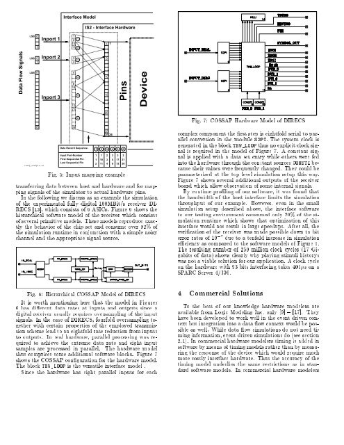
Interface Model<br />
IS2 - Interface <strong>Hardware</strong><br />
LSB 0<br />
3<br />
Inport 1<br />
1<br />
2<br />
10<br />
11<br />
1<br />
2<br />
1 1<br />
Data Flow Signals<br />
LSB<br />
0<br />
1<br />
LSB 0<br />
15<br />
inmap_example.id<br />
Inport 2<br />
Inport 3<br />
3<br />
4<br />
5<br />
8<br />
18<br />
12<br />
21<br />
26<br />
Data Record Sequence<br />
Input Port-Number<br />
First Sequential Pin<br />
Last Sequential Pin<br />
3<br />
4<br />
5<br />
6<br />
1<br />
1<br />
2<br />
5<br />
10<br />
15<br />
20<br />
25<br />
26 26<br />
1 2<br />
10 3<br />
11 4<br />
Pins<br />
1 2 3 4 5 6<br />
3 3 3<br />
5 17 21<br />
8 12 26<br />
Fig. 5: Input mapping example<br />
Device<br />
transferring data between host and hardware and for mapping<br />
signals of <strong>the</strong> simulator to actual hardware pins.<br />
In <strong>the</strong> following we discuss as an example <strong>the</strong> simulation<br />
of <strong>the</strong> experimental fully digital 100MBit/s receiver DI-<br />
RECS [13], which consists of 6 ASICs. Figure 6 shows <strong>the</strong><br />
hierarchical software model of <strong>the</strong> receiver which consists<br />
of several primitive models. These models reproduce exactly<br />
<strong>the</strong> behavior of <strong>the</strong> chip set and consume over 92% of<br />
<strong>the</strong> simulation runtime in conjunction <strong>with</strong> a simple noisy<br />
channel and <strong>the</strong> appropriate signal source.<br />
Fig. 7: <strong>COSSAP</strong> <strong>Hardware</strong> Model of DIRECS<br />
complex component <strong>the</strong> rst step is eightfold serial to parallel<br />
conversion in <strong>the</strong> module S2PI. The system clock is<br />
generated in <strong>the</strong> block THW_LOOP thus no explicit clock signal<br />
is required in <strong>the</strong> model of Figure 7. A constant signal<br />
is applied <strong>with</strong> a data set entry while o<strong>the</strong>rs were fed<br />
into <strong>the</strong> hardware through <strong>the</strong> constant sources CONSTI because<br />
<strong>the</strong>ir values were frequently changed. They could be<br />
parameterized at <strong>the</strong> top level simulation setup this way.<br />
Figure 7 shows several additional outputs of <strong>the</strong> receiver<br />
board which allow observation of some internal signals.<br />
By runtime proling of our software, it was found that<br />
<strong>the</strong> bandwidth of <strong>the</strong> host interface limits <strong>the</strong> simulation<br />
throughput of our example. However, even in <strong>the</strong> small<br />
simulation setup described above, <strong>the</strong> interface software<br />
to our testing environment consumed only 20% of <strong>the</strong> simulation<br />
runtime which shows that optimization of this<br />
interface would not result in large speedups. After all, <strong>the</strong><br />
verication of <strong>the</strong> receiver was made possible down to bit<br />
error rates of 10 ;7 due to a tenfold increase in simulation<br />
eciency as compared to <strong>the</strong> software models of Figure 6.<br />
The resulting number of 250 million clock cycles (17 Gigabits<br />
of data) shows clearly why playing stimuli historys<br />
was not a viable solution for our application. A clock cycle<br />
on <strong>the</strong> hardware <strong>with</strong> 93 bits interfacing takes 400s on a<br />
SPARC Server 4/330.<br />
Fig. 6: Hierarchical <strong>COSSAP</strong> Model of DIRECS<br />
It is worth mentioning here that <strong>the</strong> model in Figures<br />
6 has dierent data rates at inputs and outputs since a<br />
digital receiver usually requires oversampling of <strong>the</strong> input<br />
signals. In <strong>the</strong> case of DIRECS, fourfold oversampling toge<strong>the</strong>r<br />
<strong>with</strong> certain properties of <strong>the</strong> employed transmission<br />
scheme lead to an eightfold rate reduction from inputs<br />
to outputs. In real hardware, parallel processing was required<br />
to achieve <strong>the</strong> extreme data rate and eight input<br />
samples are processed in parallel. The hardware model<br />
thus comprises some additional software blocks. Figure 7<br />
shows <strong>the</strong> <strong>COSSAP</strong> conguration for <strong>the</strong> hardware model.<br />
The block THW_LOOP is <strong>the</strong> versatile interface model .<br />
Since <strong>the</strong> hardware has eight parallel inputs for each<br />
4 Commercial Solutions<br />
To <strong>the</strong> best of our knowledge hardware modelers are<br />
available from Logic Modeling Inc. only [9] { [17]. They<br />
have beendevelopedtowork well in <strong>the</strong> event driven context<br />
but integration intoadataowcontext would be possible<br />
as well. While data ow simulations do not need timing<br />
information, event driven simulations do (see section<br />
2.1). In commercial hardware modelers timing is added in<br />
software by means of timing models ra<strong>the</strong>r than by measuring<br />
<strong>the</strong> response of <strong>the</strong> device which would require much<br />
more costly interface hardware. Thus <strong>the</strong> accuracy of <strong>the</strong><br />
timing model underlies <strong>the</strong> same restrictions as in standard<br />
software models. In commercial hardware modelers