Hardware \in the Loop" Simulation with COSSAP: Closing the ... - ICE
Hardware \in the Loop" Simulation with COSSAP: Closing the ... - ICE
Hardware \in the Loop" Simulation with COSSAP: Closing the ... - ICE

Create successful ePaper yourself
Turn your PDF publications into a flip-book with our unique Google optimized e-Paper software.
implications and restrictions of data ow driven simulations<br />
in conjunction <strong>with</strong> hardware modeling are discussed.<br />
The advantages are claried as compared to hardware<br />
modeling in conjunction <strong>with</strong> event driven simulaton,<br />
which is already supported by commercially available<br />
products [9,10].<br />
S<br />
Clock<br />
Event<br />
Time<br />
2 <strong>Hardware</strong> Modeling and Data Flow <strong>Simulation</strong><br />
We will briey introduce <strong>the</strong> concept of a signal in a<br />
data ow driven simulation in this section to prepare <strong>the</strong><br />
ground for a clear discussion of advantages and limitations<br />
of hardware modeling in <strong>the</strong> context of a data ow driven<br />
simulation.<br />
2.1 Signal Paradigms<br />
<strong>Hardware</strong> modeling requires <strong>the</strong> generation of all physical<br />
signals that are required to run <strong>the</strong> hardware controlled<br />
by <strong>the</strong> simulation. Thus <strong>the</strong> clear understanding of <strong>the</strong><br />
meaning of a signal in <strong>the</strong> simulation (<strong>the</strong> signal paradigm)<br />
is a prerequisite for <strong>the</strong> integration of hardware in <strong>the</strong> loop.<br />
A signal paradigm denes<br />
<strong>the</strong> relation of <strong>the</strong> value of a signal to <strong>the</strong> ongoing<br />
(virtual) simulation time.<br />
at which time a simulation model is red to compute<br />
new values of its output signals (module scheduling).<br />
Dierent signal paradigms reect dierent levels of abstraction<br />
of a physical signal which exhibit a value at every<br />
point of time and is thus not generally representable in a<br />
digital computer. In digital system design two important<br />
paradigms are <strong>the</strong> event driven [11] and data ow driven<br />
signal paradigms [12,1]. Table 1 lists <strong>the</strong> basic properties<br />
of <strong>the</strong>se signal paradigms.<br />
Tab. 1: Signal Paradigms<br />
signal signal/time scheduling used<br />
paradigm relation scheme in<br />
event value & time change of an VHDL<br />
driven of change input signal etc.<br />
data ow only sequence all necessary input <strong>COSSAP</strong><br />
driven of values samples available etc.<br />
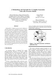
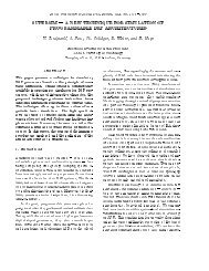
Event driven simulations are based on <strong>the</strong> idea that<br />
a signal can be described by a sequence of events which<br />
describe a signal change. The event isthus characterized<br />
by<strong>the</strong>newvalue of <strong>the</strong> related signal and <strong>the</strong> time at which<br />
<strong>the</strong> change occurs. A model needs to be red only when an<br />
input signal is changed by suchanevent. The red model<br />
<strong>the</strong>n computes <strong>the</strong> new values of its output signals. The<br />
associated events are inserted into an event table which is<br />
managed by <strong>the</strong> kernel of <strong>the</strong> simulator.<br />
Event driven simulations allow tosimulate circuit behavior<br />
precise enough for chip sign o, including eg analysis<br />
of setup and hold times. On <strong>the</strong> o<strong>the</strong>r hand <strong>the</strong> nature<br />
of <strong>the</strong> paradigm requires that all control signals like clock<br />
Time<br />
Fig. 1: Event driven signal representation<br />
and reset in synchronous designs are explicit since only<br />
<strong>the</strong> association of clock edges and signal values allow to<br />
determine what <strong>the</strong> meaningful data <strong>with</strong> respect to <strong>the</strong><br />
implemented chip function is (see Figure 1).<br />
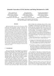
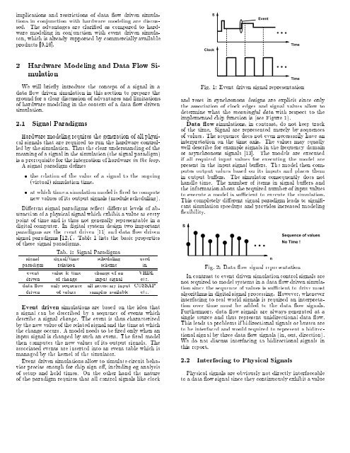
Data ow simulations, in contrast, do not keep track<br />
of <strong>the</strong> time. Signal are represented merely by sequences<br />
of values. The sequence does not even necessarily have an<br />
interpretation on <strong>the</strong> time axis. The values may equally<br />
well describe for example signals in <strong>the</strong> frequency domain<br />
or asynchronous signals [13]. The models are executed<br />
if all required input values for executing <strong>the</strong> model are<br />
present in <strong>the</strong> input signal buers. The model <strong>the</strong>n computes<br />
output values based on its inputs and places <strong>the</strong>m<br />
in output buers. The simulator consequently does not<br />
handle time. The number of items in signal buers and<br />
<strong>the</strong> information about <strong>the</strong> required number of input values<br />
to execute a model is sucient to execute <strong>the</strong> simulation.<br />
This completely dierent signal paradigm leads to signicant<br />
simulation speedups and provides increased modeling<br />
exibility.<br />
S<br />
Fig. 2: Data ow signal representation<br />
n<br />
Sequence of values<br />
No Time !<br />
In contrast to event driven simulation control signals are<br />
not required to model systems in a data owdriven simulation<br />
since <strong>the</strong> sequence of values is sucient todrivemost<br />
algorithms in digital signal processing. However, whenever<br />
interfacing to real world signals is required an interpretation<br />
over time must be added to <strong>the</strong> data ow signals.<br />
Fur<strong>the</strong>rmore, data ow signals are always generated at a<br />
single source and thus represent unidirectional data ow.<br />
This leads to problems if bidirectional signals or busses are<br />
to be interfaced and would required to represent a bidirectional<br />
signal by three data ow signals (in, out, direction).<br />
We do not discuss interfacing to bidirectional signals in<br />
this report.<br />
2.2 Interfacing to Physical Signals<br />
Physical signals are obviously not directly interfaceable<br />
to a data ow signal since <strong>the</strong>y continuously exhibit a value