a design of the novel coupled-line bandpass filter using defected ...
a design of the novel coupled-line bandpass filter using defected ...
a design of the novel coupled-line bandpass filter using defected ...

You also want an ePaper? Increase the reach of your titles
YUMPU automatically turns print PDFs into web optimized ePapers that Google loves.
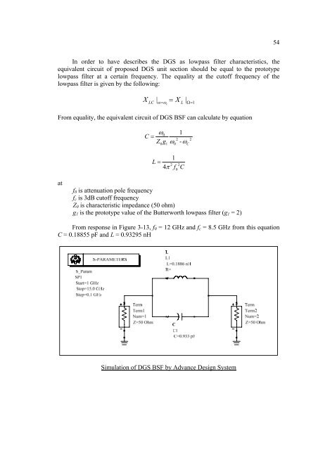
54In order to have describes <strong>the</strong> DGS as lowpass <strong>filter</strong> characteristics, <strong>the</strong>equivalent circuit <strong>of</strong> proposed DGS unit section should be equal to <strong>the</strong> prototypelowpass <strong>filter</strong> at a certain frequency. The equality at <strong>the</strong> cut<strong>of</strong>f frequency <strong>of</strong> <strong>the</strong>lowpass <strong>filter</strong> is given by <strong>the</strong> following:XLC| = X |ω= ω L Ω= 1cFrom equality, <strong>the</strong> equivalent circuit <strong>of</strong> DGS BSF can calculate by equationC =ωZg102 20 1ω0-ωC1L =4πf C2 20atf 0 is attenuation pole frequencyf c is 3dB cut<strong>of</strong>f frequencyZ 0 is characteristic impedance (50 ohm)g 1 is <strong>the</strong> prototype value <strong>of</strong> <strong>the</strong> Butterworth lowpass <strong>filter</strong> (g 1 = 2)From response in Figure 3-13, f 0 = 12 GHz and f c = 8.5 GHz from this equationC = 0.18855 pF and L = 0.93295 nHSimulation <strong>of</strong> DGS BSF by Advance Design System