Force, pressure and strain measurements for traditional heavy ...
Force, pressure and strain measurements for traditional heavy ...
Force, pressure and strain measurements for traditional heavy ...

You also want an ePaper? Increase the reach of your titles
YUMPU automatically turns print PDFs into web optimized ePapers that Google loves.
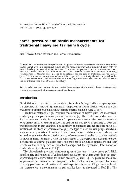
Rakenteiden Mekaniikka (Journal of Structural Mechanics)Vol. 44, No 4, 2011, pp. 309-329<strong>Force</strong>, <strong>pressure</strong> <strong>and</strong> <strong>strain</strong> <strong>measurements</strong> <strong>for</strong><strong>traditional</strong> <strong>heavy</strong> mortar launch cycleJuha Toivola, Seppo Moilanen <strong>and</strong> Henna-Riitta JussilaSummary. The measurement applications of <strong>pressure</strong>, <strong>for</strong>ces <strong>and</strong> <strong>strain</strong>s <strong>for</strong> <strong>traditional</strong> <strong>heavy</strong>mortar launch cycle are presented. Especially the processing method of measured <strong>strain</strong> data <strong>for</strong>launch loading determination is discussed. The chamber <strong>pressure</strong> estimates calculated frommeasured tube <strong>strain</strong>s are evaluated <strong>and</strong> the <strong>pressure</strong> calculation method includingcompensation of thermal stress proved to be relevant <strong>for</strong> the case of <strong>traditional</strong> mortar launchcycle. The transversal component of socket <strong>for</strong>ce proved to be insignificant compared to theaxial <strong>for</strong>ce component. The ground base type had negligible effect on measured socket <strong>for</strong>ces<strong>and</strong> on extreme base plate <strong>strain</strong>s in this study.Key words: mortars, mortar tubes, mortar base plates, <strong>strain</strong> gages, <strong>for</strong>ce measurement,<strong>pressure</strong> measurement, <strong>strain</strong> measurement, test firingsIntroductionThe definitions of <strong>pressure</strong> terms <strong>and</strong> their relationship <strong>for</strong> large caliber weapon systemsare presented in st<strong>and</strong>ard [1]. The main component of mortar launch loading is a gas<strong>pressure</strong> of burning propellant charge during internal ballistic cycle of shot.Traditional methods of gas <strong>pressure</strong> measurement of <strong>heavy</strong> guns are mechanicalcrusher gauge <strong>and</strong> piezoelectric <strong>pressure</strong> transducer [2]. The crusher method is based onthe measurement of the de<strong>for</strong>mation of copper element due to the <strong>pressure</strong> resultant<strong>for</strong>ce on the piston of crusher gauge. The crusher method gives an estimate of peak gas<strong>pressure</strong> of shot in gun chamber. The accuracy of estimated crusher <strong>pressure</strong> value is afunction of the shape of <strong>pressure</strong> curve p(t), the type of used crusher gauge <strong>and</strong> dynamicalmaterial properties of crusher element. Some tailored calibration methods have tobe used to guarantee the required accuracy of measurement results <strong>for</strong> crusher method,as shown in Refs. [3] <strong>and</strong> [4]. Also the construction of the weapon can cause differencesin the results of crusher <strong>pressure</strong>s due to the chamber volume, tube dimensions <strong>and</strong> theireffects on the burning rate of propellant charge <strong>and</strong> the dynamical de<strong>for</strong>mation ofcrusher element, as shown in Ref. [7].The piezoelectric <strong>pressure</strong> transducer gives a <strong>pressure</strong> vs. time curve p(t). Highsampling rate <strong>and</strong> reliability of calibration of transducer can guarantee the high accuracyof <strong>pressure</strong> peak determination <strong>for</strong> launch <strong>pressure</strong> [9] <strong>and</strong> [10]. The <strong>pressure</strong>s measuredby piezoelectric transducers are supposed to be exact values of <strong>pressure</strong>, but someaccuracy problems in calibration still exist especially in cases of high <strong>pressure</strong> levels<strong>and</strong> <strong>pressure</strong> wave determination in gun applications, as discussed in Ref. [8]. The309
drawback of piezoelectric transducer is that some kind of mechanical housing (drilling<strong>and</strong> tapping) <strong>for</strong> transducer should be machined into the weapon, which cause structuralweaknesses <strong>and</strong> prevent the service use of <strong>pressure</strong> test weapons. The third <strong>pressure</strong>measurement method is a combination of crusher <strong>and</strong> piezoelectric methods. The piezoelectrictransducer <strong>and</strong> its electronics are installed in cylindrical metallic body, whichcan be put into gun chamber <strong>and</strong> used like a <strong>traditional</strong> crusher gauge. Nowadays thesizes of piezoelectric crusher gauges allow their use also in mortar chambers as <strong>pressure</strong>measurement sensors [11].The measurement of gun tube <strong>strain</strong>s <strong>and</strong> <strong>strain</strong> data analysis offer a reliablecomparison method <strong>for</strong> ballistic <strong>pressure</strong> measurement. Because the gun tubes are thickwall cylinders with high manufacturing quality (small tolerances in dimensions) <strong>and</strong> thegeometrical changes of shape are usually smooth, the <strong>traditional</strong> equations of elasticityapply well <strong>for</strong> de<strong>for</strong>mation vs. <strong>pressure</strong> load applications [7], [12], [13], [14] <strong>and</strong> [15].Special application of tube <strong>strain</strong> measurement is an evaluation of rotating b<strong>and</strong> loadingon gun tubes, which is important <strong>for</strong> rifled cannon tubes. The application details of b<strong>and</strong><strong>pressure</strong> <strong>measurements</strong> <strong>and</strong> calculations are discussed in Refs. [16], [17] <strong>and</strong> [18] <strong>and</strong> intheir sub-references.During mortar launch cycle the <strong>pressure</strong> <strong>for</strong>ce presses the breech piece towards thebase plate <strong>and</strong> the ground. The value of socket <strong>for</strong>ce can be estimated as a resultant<strong>for</strong>ce of chamber <strong>pressure</strong>, but dynamic effects of structures <strong>and</strong> the stiffness of groundbase can cause disturbances on reaction <strong>for</strong>ce values. The results of test firing <strong>for</strong>ces<strong>and</strong> <strong>strain</strong> <strong>measurements</strong> can be used as a base of structural designing [19], designing<strong>and</strong> evaluation of mechanical fatigue laboratory tests <strong>and</strong> the laboratory acceptance testsof mortar base plate [20].The modern mortar ammunition can cause higher <strong>pressure</strong> <strong>and</strong> <strong>for</strong>ce loads due to theincreased weight of projectile <strong>and</strong> higher muzzle velocity than earlier versions of mortarammunition. The requirements of low weight of weapon construction <strong>and</strong> good launchstability together with the overall usability of the weapon in all types of ground basesare more or less in conflict with each other.Measurement configuration in mortar test firingThe purpose of mortar test firing discussed in this paper was to evaluate the socket<strong>for</strong>ces <strong>and</strong> <strong>strain</strong>s in base plate structure when different kinds of ammunition were fired.Some results of earlier test firings were available in the research report [6], when thebase plate was positioned in extreme soft s<strong>and</strong>y soil or a rigid concrete bed without baseplate was used. In this study the ground bases were realistic service cases: Base plate ingravel soil <strong>and</strong> in s<strong>and</strong>y soil. The s<strong>and</strong>y soil ground was created by digging a largecavity in gravel soil <strong>and</strong> then filling it with s<strong>and</strong>.Axial <strong>and</strong> hoop <strong>strain</strong>s of outside surface of tube chamber section were measured byusing biaxial 0 o /90 o <strong>strain</strong> gage rosette. The chamber <strong>pressure</strong> was calculated from themeasured <strong>strain</strong> data. Direct <strong>pressure</strong> measurement method was aimed to be used <strong>for</strong>over<strong>pressure</strong> rounds by using piezoelectric <strong>pressure</strong> transducer, but the measurementfailed.310
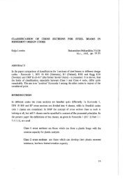
Special breech piece with dog-bone geometry was used <strong>for</strong> socket <strong>for</strong>cemeasurement, when service rounds or equivalent rounds were fired. The cylindrical partof the breech piece body was instrumented as a <strong>for</strong>ce transducer by tri-axial <strong>strain</strong> gagerosettes as shown in figure 1. Finally the base plate was also instrumented by <strong>strain</strong>gages. The positions of <strong>strain</strong> gages are shown in figure 2.Figure 1. Special breech piece <strong>for</strong> socket <strong>for</strong>ce measurement. Strain gage instrumentation [5]<strong>and</strong> real structure..Figure 2. Strain gage positions on base plate311
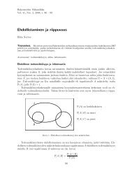
Figure 3. Socket <strong>for</strong>ces acting on instrumented breech piece, base plate is not shown. Straingage rosette <strong>for</strong> <strong>pressure</strong> measurement located on chamber section of tube, distance of 350 mmfrom tube base end.Test weapon <strong>and</strong> ammunitionsTest weapon was Finnish 120 KRH 92 mortar (Patria 120 mm long range mortar) withspecial <strong>for</strong>ce measurement breech piece. The projectiles used in tests were <strong>traditional</strong>120 mm HE mortar shell (projectile mass m p ≈13 kg) <strong>and</strong> 120 mm ballistic slug(projectile mass range m p =(15...20) kg). Different charge zones from low <strong>pressure</strong>s upto over<strong>pressure</strong> levels were used. The weapon <strong>and</strong> examples of used ammunition typesare shown in figures 4 <strong>and</strong> 5, respectively.Totally 34 rounds were fired in test including: 4 + 4 + 2 = 10 warmers <strong>and</strong> base plate stabilizing rounds 3 + 5 + 8 = 16 service rounds 3 + 5 = 8 <strong>pressure</strong> control <strong>and</strong> over<strong>pressure</strong> rounds on s<strong>and</strong>y soil.312
Figure 4. Traditional muzzle loaded 120 KRH 92 mortar on gravel soil be<strong>for</strong>e firing. The maincomponents of mortar are: Base plate, special breech piece <strong>for</strong> socket <strong>for</strong>ce <strong>measurements</strong>, tube,sight unit <strong>and</strong> bipod assembly.Figure 5. Traditional 120 mm HE shells (left) <strong>and</strong> ballistic slugs (right) with charge modules.Measurement hardwareThe hardware of <strong>measurements</strong> was: Strain gages on base plate <strong>and</strong> tube;o Kyowa KFG-5-120-C1-11L3MR, k=2.10, uniaxialo Kyowa KFG-2-120-D16-11L5M3S, k=2.06, biaxial 0 o /90 o rosetteo Kyowa KFG-5-120-D16-11L5M3S, k=2.06, biaxial 0 o /90 o rosette. Strain gages on <strong>for</strong>ce measurement breech piece;o HBM RY31 6/120, k=1.93, tri-axial 0 o /45 o /90 o rosette. Kistler piezoelectric <strong>pressure</strong> transducer K 6215 (used <strong>for</strong> over<strong>pressure</strong> rounds) PCB charge amplifier 422D13/A (used <strong>for</strong> over<strong>pressure</strong> rounds)313
IOTech Wavebook Data Acquisition Unit IOTech WBK 16 Strain Gage Signal Conditioner LapTop PC Computer Weibel W-700M Velocity Analyzer Citius C10 <strong>and</strong> C100 Centurio high speed video cameras Zwick/Z250 tensile test machine <strong>for</strong> calibrating of axial <strong>for</strong>ce of breech piece <strong>for</strong>socket <strong>for</strong>ce measurement Tamtron MCS 0-6300 kg electronic scale <strong>for</strong> calibrating of transversal socket<strong>for</strong>ces of breech piece.Sampling rate f s =40 kHz was used in <strong>measurements</strong> <strong>and</strong> totally 20 channels wereused <strong>for</strong> <strong>strain</strong> <strong>and</strong> <strong>for</strong>ce <strong>measurements</strong>: 5 channels <strong>for</strong> socket <strong>for</strong>ces <strong>measurements</strong>;o 1 full bridge <strong>for</strong> axial <strong>for</strong>ce F xo 2 full bridges <strong>for</strong> transversal <strong>for</strong>ces F y <strong>and</strong> F z (shear de<strong>for</strong>mation)o 2 half bridges <strong>for</strong> transversal <strong>for</strong>ces F y <strong>and</strong> F z (bending de<strong>for</strong>mation). 15 channels <strong>for</strong> <strong>strain</strong> measurement (¼ bridges);o 2 channels of tube <strong>strain</strong>s <strong>for</strong> <strong>pressure</strong> measuremento 13 channels <strong>for</strong> base plate <strong>strain</strong> measurement.One channel was used <strong>for</strong> direct chamber <strong>pressure</strong> measurement by piezoelectrictransducer <strong>for</strong> over<strong>pressure</strong> rounds, when st<strong>and</strong>ard <strong>pressure</strong> measurement breech piecewas used instead of special <strong>for</strong>ce measurement breech piece. The later one wasoriginally designed <strong>for</strong> <strong>measurements</strong> of the loading level of service round firing.Data analysis softwareThe measured data was stored <strong>and</strong> analysed by using Matlab software.Computation of <strong>pressure</strong> estimates from measured dataTheoretical basis of <strong>pressure</strong> computation from <strong>strain</strong>s of tube wallAxial <strong>and</strong> hoop <strong>strain</strong>s were measured at outer surface of tube where axial <strong>and</strong> hoopstresses arise from following phenomena:Axial stress: tube bending (including bending vibration) axial rigid body acceleration (including rigid body vibration of the tube) axial elastic vibration axial loading by friction between projectile <strong>and</strong> inner surface of the tube(insignificant in presented case) inner surface radial <strong>pressure</strong> loading variation in axial direction (insignificantin presented case) thermal stress due to nonlinear temperature distribution.Hoop stress: inner surface radial loading by projectile (insignificant in presented case) inner surface radial loading by gas <strong>pressure</strong> thermal stress due to nonlinear temperature distribution.314
Axial stress is denoted asa aB aA ap aT, (1)where aB is bending stress, aA axial stress arising from purely axial phenomena (axialacceleration, vibration <strong>and</strong> loading), ap axial stress caused by inner surface radialloading variation in axial direction <strong>and</strong> aT axial stress due to nonlinear temperaturedistribution. Similarly hoop stress is decomposed as p T, (2)where p is hoop stress caused by inner surface radial loadings <strong>and</strong> T hoop stress dueto nonlinear temperature distribution. Generalised Hooke's law <strong>for</strong> plane stress state is 1 aTEaa T 1 (3)ET T,where E is Young’s modulus, Poisson’s factor, temperature expansion coefficient, , a <strong>and</strong> T are hoop, axial <strong>and</strong> thermal <strong>strain</strong> respectively <strong>and</strong> T change of temperature.During internal ballistic cycle lasting <strong>for</strong> some milliseconds, temperature change atouter surface is small. For this reason thermal <strong>strain</strong> T Tis neglected in thesequel. For longer measurement time this naturally does not hold <strong>and</strong> <strong>strain</strong> gageresponse curve <strong>for</strong> thermal <strong>strain</strong> is needed if this term is kept in analysis (<strong>for</strong> ideallytemperature compensated <strong>strain</strong> gages response to thermal <strong>strain</strong> is zero) <strong>and</strong>temperature should be measured or thermal <strong>strain</strong> should be compensated by anothermeans.According to Ref. [21] <strong>for</strong> stationary case of long axially free cylinder underaxisymmetric axially uni<strong>for</strong>m thermal loading it can be shown that axial <strong>and</strong> hoopstresses at outer surface are equal. In Ref. [21] it has been shown that thermally inducedvibrations are prominent <strong>for</strong> slender beams <strong>and</strong> thin plates. Based on these classicalresults, it is assumed that thermally induced vibrations are insignificant <strong>and</strong> axial <strong>and</strong>hoop thermal stresses at outer surface are equal, i.e. aT = T = T .Outer surface hoop stress <strong>for</strong> long open-ended thick wall cylinder under internaluni<strong>for</strong>m <strong>pressure</strong> is2 p , (4)2 1where p is the internal <strong>pressure</strong>, D / d the wall ratio, D the outer diameter of thecylinder <strong>and</strong> d the inner diameter of the cylinder. Although assumptions behindequation (4) are not completely fulfilled in the case of gun tube, results <strong>and</strong>interpretations based on this approach have been found useful.In order to cancel out some unwanted phenomena from computed results, weightedsum of <strong>strain</strong> components is written as315
1 2 p 11 a 1 aA aB ap11 T. (5)2E 1EEIt can be seen that by choosing weighting factor 1cancels out thermal stress, butaxial phenomena remains. Choosing axial phenomena can be cancelled out, butthermal stress remains. Solving internal <strong>pressure</strong> <strong>for</strong> these cases results 1: 22 1E 1p aaA aB ap2 12(6) :22 1E 1p a2T.2 12(7)From equations (6) <strong>and</strong> (7) it is seen, that some error is unavoidable. Choice should bemade according to which error seems to be smaller, error caused by thermal stress orerror caused by axial phenomena.According to analysis presented above internal <strong>pressure</strong> estimates are 1: 2 1Ep1 a2 1(8) :2 1Ep2 a. 22 1(9)When left h<strong>and</strong> side <strong>pressure</strong>s in equations (6) <strong>and</strong> (7) are taken as real gas <strong>pressure</strong>,using equations (8) <strong>and</strong> (9) results2 1p1 p aAaBap2(10)2 1p2 p T,2(11)where p is a real gas <strong>pressure</strong>. Because thermal stress T is positive at the outer surface,estimate p 2 always overestimates the real <strong>pressure</strong>.In the absence of axial phenomena it is possible to estimate thermal stress T atouter surface. Using weighting factor = 1/ in equation (5) <strong>and</strong> solving <strong>for</strong> thermalstress yieldsET aaAaBap. 21(12)Thermal stress estimate isET est a,21(13)<strong>and</strong> it’s relationship to true thermal stress TT , est T aA aB ap. (14)316
Other <strong>pressure</strong> estimatesIn actual <strong>measurements</strong> <strong>pressure</strong> estimate from direct <strong>pressure</strong> measurement wasdenoted as p 3 <strong>for</strong> over<strong>pressure</strong> rounds. Because the direct <strong>pressure</strong> <strong>measurements</strong> usingpiezoelectric <strong>pressure</strong> transducer failed, the results of them are not presented.In this study fourth possibility to estimate tube <strong>pressure</strong> is to compute it from socketaxial <strong>for</strong>ce F x measurement:Fxp4 , (15)Awhere A is a pressurized area of tube cross section.When socket axial <strong>for</strong>ce is assumed to be positive <strong>for</strong> compressive <strong>for</strong>ce <strong>and</strong>acceleration a is assumed to be positive towards the rear end of the tube, the equation ofmotion <strong>for</strong> the tube assembly ispA Fx ma , (16)where p is a real gas <strong>pressure</strong> at the bottom of the tube <strong>and</strong> m is the mass of tube <strong>and</strong>breech piece. Combining equations (15) <strong>and</strong> (16) it is seen thatmap4 p . (17)AAssuming that axial stress in equation (10) is due to rigid body acceleration,aA mta At, <strong>and</strong> using numerical values <strong>for</strong> a particular case in h<strong>and</strong> it is found that2 1A mtma map1 p p 0.35 , (18)2 Atm AAwhere A t is the cross sectional area of tube wall at <strong>strain</strong> measurement point on the tube<strong>and</strong> m t is the partial mass of the tube from the <strong>strain</strong> gage position to muzzle end.At the beginning of the internal ballistic cycle acceleration is positive <strong>and</strong> bothestimates p 1 <strong>and</strong> p 4 underestimate the true <strong>pressure</strong>. Comparing equations (17) <strong>and</strong> (18)it is readily seen that error caused by axial rigid body acceleration a is clearly smaller inestimate p 1 than in estimate p 4 <strong>and</strong> thus at the beginning of the internal ballistic cycleestimate p 1 should exceed estimate p 4 .Choice <strong>for</strong> chamber <strong>pressure</strong> estimateFor over<strong>pressure</strong> rounds <strong>pressure</strong> was intended to be measured using piezoelectrictransducer, <strong>and</strong> <strong>strain</strong> gages were meant to be a backup <strong>pressure</strong> sensor if direct <strong>pressure</strong>measurement fails. Un<strong>for</strong>tunately this was what happened because of poor chargeamplifier action. There<strong>for</strong>e direct <strong>pressure</strong> measurement results <strong>for</strong> these rounds weredoubtful. For service rounds <strong>strain</strong> gages on the tube surface were intended to act onlyas <strong>pressure</strong> measurement sensor, because special <strong>for</strong>ce measurement breech piece wasused <strong>and</strong> direct <strong>pressure</strong> measurement was impossible. This situation necessitatedanalysis <strong>and</strong> comparison of different <strong>pressure</strong> estimators <strong>and</strong> a choice between them inthis study. The comparison of direct <strong>pressure</strong>s with <strong>strain</strong> <strong>pressure</strong>s is discussed shortlyin Ref. [7].Choice between <strong>pressure</strong> estimates p 1 <strong>and</strong> p 2 must be based on measured data <strong>and</strong>type of weapon. Experience from several <strong>measurements</strong> of recoiling cannon has shownthat acceleration of recoil movement <strong>and</strong> muzzle brake <strong>for</strong>ce is clearly visible in tube317
<strong>strain</strong> <strong>measurements</strong> <strong>and</strong> so axial effects need to be compensated. Also rotating b<strong>and</strong><strong>pressure</strong> creates axial stress when it passes measurement point as shown in Refs. [16],[17] <strong>and</strong> [18]. For a <strong>traditional</strong> smooth bore mortar there is no recoil mechanism, nomuzzle brake <strong>and</strong> no rotating b<strong>and</strong> passing present. Based on these considerations bothof <strong>pressure</strong> estimates (p 1 , p 2 ) can be chosen <strong>for</strong> <strong>traditional</strong> mortar firing.In figure 6 measured hoop <strong>and</strong> axial <strong>strain</strong>s are presented <strong>for</strong> a typical mortar shot.As can be seen there is no significant axial or bending vibration visible after internalballistic cycle <strong>and</strong> hence it can be assumed that elastic vibrations are absent.Considering axial effects, only rigid body acceleration <strong>and</strong> thermal stress could bepresent. Effect of thermal stress is visible in figure 6 after internal ballistic cycle, whereboth axial <strong>and</strong> hoop <strong>strain</strong> settles rapidly to approximate level of 50 m/m correspondingto thermal stress of 15 MPa at outer surface. This also proves experimentally,that after internal ballistic cycle both axial <strong>and</strong> hoop <strong>strain</strong>s <strong>and</strong> stresses are equalalthough temperature field is non-stationary.100Axial <strong>strain</strong>600Hoop <strong>strain</strong>50050400Strain (10 -6 )0Strain (10 -6 )300200-501000-1001.2 1.4 1.6 1.8 2 2.2 2.4Time (s)-1001.2 1.4 1.6 1.8 2 2.2 2.4Time (s)Figure 6. Axial <strong>and</strong> hoop <strong>strain</strong> of tube <strong>for</strong> typical mortar shot.140p 1120100p 2p 4Pressure (MPa)8060402001.66 1.662 1.664 1.666 1.668 1.67 1.672 1.674 1.676Time (s)Figure 7. Pressure estimates p 1 , p 2 <strong>and</strong> p 4 .318
Pressure estimates p 1 , p 2 <strong>and</strong> p 4 are shown in figure 7 <strong>for</strong> a typical service roundwhen the soil base has been compacted by previous rounds. There are several issuesvisible: Estimate p 2 , which is known to overestimate real <strong>pressure</strong>, always exceedsestimate p 1 . Estimate p 1 , which underestimates real <strong>pressure</strong> less than p 4 when acceleration ispositive, exceeds estimate p 4 almost to the <strong>pressure</strong> peak. When estimates p 1 <strong>and</strong>p 4 coincide, acceleration changes sign (within the measurement <strong>and</strong> analysisaccuracy). Thermal stress, which is the only error source <strong>for</strong> estimate p 2 , developes veryrapidly <strong>and</strong> has almost reached it’s final value at <strong>pressure</strong> peak. Estimate p 2 clearly overestimates <strong>pressure</strong> peak value. For this round estimate p 1 probably slightly overestimates <strong>pressure</strong> peak value. For this round estimate p 4 apparently overestimates <strong>pressure</strong> peak value, becauseacceleration has changed sign be<strong>for</strong>e peak <strong>and</strong> estimate p 4 (<strong>and</strong> p 1 ) overestimatesthe real <strong>pressure</strong> under negative acceleration (after crossing of estimates p 1 <strong>and</strong>p 4 ).Based on the observations above, estimate p 1 seems to be the best choice. Pressurepeak value is an important result parameter. Because estimate p 2 always overestimatesthe real <strong>pressure</strong>, <strong>pressure</strong> peak value <strong>and</strong> also gas impulse computation will beerroneous. For estimate p 4 it is not known in advance whether it overestimates orunderestimates <strong>pressure</strong> peak value because acceleration could change sign be<strong>for</strong>e orafter <strong>pressure</strong> peak depending on the characteristics of the soil base.Thermal stress of tubeIn figure 8 typical result <strong>for</strong> estimated thermal stress together with <strong>pressure</strong> estimates p 1<strong>and</strong> p 2 is shown. After internal ballistic cycle thermal stress rapidly settles toapproximate level of 27 MPa <strong>for</strong> this round. During internal ballistic cycle thermalstress estimate rises almost immediately up to the final level <strong>and</strong> then drops be<strong>for</strong>eclimbing up to the final level again. This is because axial acceleration effect issuperimposed into the estimate. At the beginning of internal ballistic cycle axialacceleration is positive <strong>and</strong> hence thermal stress estimate overestimates the real thermalstress (Eq. 14). However, thermal stress builds up very rapidly. At the beginning of theinternal ballistic cycle propellant gas temperature is higher due to burning <strong>and</strong> heattransfer into the tube is efficient. At later part of the cycle propellant gas exp<strong>and</strong>s <strong>and</strong>cools there<strong>for</strong>e reducing heat transfer.ResultsSocket <strong>for</strong>ces vs. <strong>pressure</strong>The socket <strong>for</strong>ces vs. time t curves together with the <strong>pressure</strong> p 1 (t) <strong>and</strong> tube <strong>strain</strong>curves <strong>for</strong> service round fired on s<strong>and</strong>y soil are presented in figure 9. The maximums of<strong>for</strong>ce components occurred at the same time as the maximum of gas <strong>pressure</strong>. Thedirections of “vertical” transversal <strong>for</strong>ce component F y are opposite between the319
140p 1Pressure, stress (MPa)120100806040p 2 T2001.66 1.665 1.67 1.675 1.68 1.685 1.69 1.695 1.7Time (s)Figure 8. Thermal stress estimate <strong>and</strong> <strong>pressure</strong> estimates p 1 <strong>and</strong> p 2 .measurement methods (shear or bending). This is supposed to be a consequence of nonsymmetriccontact between the socket ball of breech piece <strong>and</strong> socket cup of base plate.Because the maximum values of axial <strong>for</strong>ce F x are (30...100) times higher thanmaximums of transversal <strong>for</strong>ce components, the small eccentricity in the contact withthe socket can cause bending moment due to the axial <strong>for</strong>ce. Based on theseconsiderations measurement results relying on shear de<strong>for</strong>mation of dog bone rod wereassumed to be a better choice <strong>for</strong> transversal <strong>for</strong>ce estimations.The maximum value of axial socket <strong>for</strong>ce F x vs. maximum gas <strong>pressure</strong> p ispresented in figure 10 <strong>for</strong> different types of ground <strong>and</strong> gas <strong>pressure</strong> range (25...125)MPa. The rounds of earlier work were fired on the extremely soft s<strong>and</strong>y soil with baseplate <strong>and</strong> on the fixed socket cup on concrete bed without base plate. Previously thespecial <strong>pressure</strong> measurement tube had been used <strong>and</strong> gas <strong>pressure</strong> had been measuredusing a piezoelectric <strong>pressure</strong> sensor mounted on tube wall. The results presented inprevious report [6] are included in figure 10.In earlier work [6] it was shown that: The <strong>for</strong>ce results of soft s<strong>and</strong>y soil case were clearly lower than theoreticalgas <strong>pressure</strong> resultant <strong>for</strong>ce value max F x = max p A The effect of compaction of soft s<strong>and</strong>y soil base due to firing can be seen.Stabilising rounds (index A, marker ○) have lowest <strong>for</strong>ce value compared to<strong>pressure</strong>. The <strong>for</strong>ces increased towards to the theoretical line, when the nextseries (index B <strong>and</strong> C, marker ) were fired. The <strong>for</strong>ce values are evenhigher <strong>for</strong> series C (fired after B series round) at lower gas <strong>pressure</strong> than <strong>for</strong>the rounds of stabilising series A with higher gas <strong>pressure</strong> maximums The maximum axial <strong>for</strong>ces were ~30 % higher than theoretical gas <strong>pressure</strong>resultant <strong>for</strong>ce when the rounds were fired on fixed socket cup (marker ◊).320
Figure 10. Maximums of axial socket <strong>for</strong>ce vs. gas <strong>pressure</strong>, when the rounds were fired on thedifferent types of ground base.In this study the measured axial <strong>for</strong>ce values on both of gravel <strong>and</strong> s<strong>and</strong>y soil werepositioned near the theoretical gas <strong>pressure</strong> <strong>for</strong>ce value, relative differences were +- 5%.The <strong>for</strong>ce maximums of low <strong>and</strong> middle <strong>pressure</strong> p= (25...60) MPa stabilising roundswere a little bit lower <strong>and</strong> the <strong>for</strong>ces of high <strong>pressure</strong> service rounds (up to p~120 MPa)were a little higher than the theoretical maximum value of the gas <strong>pressure</strong> resultant inboth cases.Base plate <strong>strain</strong>s during launch cycleTube <strong>strain</strong>s, <strong>pressure</strong> estimates p 1 <strong>and</strong> p 2 <strong>and</strong> base plate <strong>strain</strong>s at <strong>strain</strong> measurementpoint 4 are presented <strong>for</strong> two rounds on gravel soil <strong>and</strong> s<strong>and</strong>y soil in figure 11. Thesesoil bases do not significantly affect tube internal <strong>pressure</strong>s estimated from tube <strong>strain</strong>s.Strain gage V41 shows typical base plate <strong>strain</strong> measurement result where no significantdependence on soil base is visible. An example of few exceptions of this behaviour is322
shown in results of <strong>strain</strong> gage V42 where <strong>strain</strong> history is clearly different <strong>for</strong> s<strong>and</strong>y<strong>and</strong> gravel soil base.2000Tube <strong>strain</strong>s2000Tube <strong>strain</strong>s1500 a 1500 a Strain (10 -6 )1000500Strain (10 -6 )100050000-5001.58 1.59 1.6 1.61Pressure estimates150-5001502.08 2.09 2.1Pressure estimatesp 1p 1Pressure (MPa)10050p 2Pressure (MPa)10050p 201.58 1.59 1.6 1.61Base plate <strong>strain</strong> V411000800010008002.08 2.09 2.1Base plate <strong>strain</strong> V41Strain (10 -6 )600400200Strain (10 -6 )60040020000Strain (10 -6 )-2001.58 1.59 1.6 1.61Base plate <strong>strain</strong> V42100500-50-100-150-200Strain (10 -6 )-200100500-50-100-150-2002.08 2.09 2.1Base plate <strong>strain</strong> V42-2501.58 1.59 1.6 1.61Time (s)2.08 2.09 2.1Time (s)Figure 11. Left column gravel soil, right column s<strong>and</strong>y soil, service rounds.-250323
4000Tube <strong>strain</strong>s4000Tube <strong>strain</strong>s3000 a 3000 a Strain (10 -6 )20001000Strain (10 -6 )2000100000-10002001.86 1.87 1.88 1.89Pressure estimates-10002001.75 1.755 1.76 1.765 1.77 1.775Pressure estimatesp 1p 1150p 2150p 2Pressure (MPa)10050Pressure (MPa)10050020001.86 1.87 1.88 1.89Base plate <strong>strain</strong> V41020001.75 1.755 1.76 1.765 1.77 1.775Base plate <strong>strain</strong> V4115001500Strain (10 -6 )1000500Strain (10 -6 )100050000-5001001.86 1.87 1.88 1.89Base plate <strong>strain</strong> V42-5001001.75 1.755 1.76 1.765 1.77 1.775Base plate <strong>strain</strong> V4200Strain (10 -6 )-100-200Strain (10 -6 )-100-200-300-300-4001.86 1.87 1.88 1.89Time (s)-4001.75 1.755 1.76 1.765 1.77 1.775Time (s)Figure 12. Left column low <strong>pressure</strong> round, right column over<strong>pressure</strong> round.324
In figure 12 tube <strong>strain</strong>s, <strong>pressure</strong> estimates p 1 <strong>and</strong> p 2 , base plate <strong>strain</strong>s V41 <strong>and</strong>V42 are presented <strong>for</strong> two extreme rounds, one with low <strong>pressure</strong> charge <strong>and</strong> another<strong>for</strong> over<strong>pressure</strong> charge. Both rounds were fired on s<strong>and</strong>y soil. Comparing <strong>pressure</strong>estimates <strong>and</strong> base plate <strong>strain</strong> V41 it is seen that maximum values of base plate <strong>strain</strong><strong>and</strong> tube internal <strong>pressure</strong> do not follow linear dependence. This is more pronouncedlyvisible in the results <strong>for</strong> <strong>strain</strong> gage V42 where <strong>strain</strong> response to low <strong>pressure</strong> round islow but to over<strong>pressure</strong> round both maximum <strong>strain</strong> level <strong>and</strong> overall behaviour of<strong>strain</strong> history are completely different.Figure 13. Base plate after service rounds firing on gravel soil (left) <strong>and</strong> on s<strong>and</strong>y soil (right).Table 1. Number of fired rounds in series, <strong>pressure</strong> estimate p 1 , socket <strong>for</strong>ce component F x <strong>and</strong>major limit value of base plate <strong>strain</strong>s <strong>for</strong> the rounds fired on the gravel base. The mean <strong>and</strong>st<strong>and</strong>ard deviation values are presented <strong>for</strong> the series including many rounds.No ofrds.p 1maxF xmaxV1maxV2minV3maxV41maxV42minMPa kN Base plate <strong>strain</strong>s µm/m (=10 -6 )(2) * 28.4 316 110 -252 35 150 N/A §§ 70 -295 -37 -120 139 -209 44 -127Std. 1.2 29.9 19 34 8 3 - 12 100 16 8 16 42 9 21V51maxV52minV61minV62minV71maxV72minV81 §maxV82min(2) * 66.7 725 240 -616 71 376 N/A 231 -803 -78 -321 359 -444 66 -365Std. 1.3 65.4 11 85 7 40 - 33 47 6 12 13 17 8 41(1) 89 968 310 -794 59 608 N/A 332 -985 -119 -492 542 -431 56 -456(1) - - Triggering signal missed, measured data was not available <strong>for</strong> this round. - -(1) 103.6 1211 417 -973 48 783 -96 449 -838 -173 -670 645 -414 50 -449(5) 117.6 1397 474 -1196 93 927 -137 534 -702 -205 -751 699 -389 161 -425Std. 1.2 8.5 4 23 12 26 31 12 77 6 10 8 35 135 34Remarks:§ Measured signals of meridional <strong>strain</strong> component V81 on side of base plate cone were noisy.§§Measured signals of tangential <strong>strain</strong> component V42 were unsettled <strong>for</strong> low <strong>pressure</strong> rounds,see figure 12.* Stabilizing rounds.325
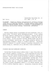
Table 2. Number of fired rounds in series, <strong>pressure</strong> estimate p 1 , socket <strong>for</strong>ce component F x <strong>and</strong>major limit value of base plate <strong>strain</strong>s on s<strong>and</strong>y base <strong>for</strong> service round <strong>and</strong> over<strong>pressure</strong> roundfiring cases. Mean <strong>and</strong> st<strong>and</strong>ard deviation values are presented <strong>for</strong> the series including manyrounds.No ofrdsp 1 F xV1 V2 V3 V41 V42 V51 V52 V61 V62 V71 V72 V81 § V82max max max min max max min max min min min max min max minMPa kN Base plate <strong>strain</strong>s µm/m (=10 -6 )(2) * 28.2 305 119 -209 50 151 N/A §§ 103 -88 -42 -199 130 -173 33 -178Std. 0.1 10.7 29 60 12 5 - 7 25 1 54 27 6 5 33(2) * 69.2 746 228 -588 142 413 -80 275 -303 -117 -436 319 -242 84 -417Std. 0.2 34.7 13 44 8 33 2 18 29 5 52 5 18 3 59(8) 118 1386 392 -1013 99 913 -220 529 -433 -242 -825 703 -374 73 -525Std. 2.1 33.8 8 30 42 69 45 35 47 7 21 69 15 27 65Pressure measurement breech piece was used after these rounds, socket <strong>for</strong>ce <strong>measurements</strong> were not available.(2) * 72.1 N/A 254 -737 106 564 -169 348 -242 -145 -513 473 -251 30 -259Std. 0.2 - 7 1 2 10 0 11 5 6 9 2 2 1 19(1) & 102 N/A 372 -989 114 839 -260 517 -307 -214 -759 689 -340 35 -401(1) & 150 N/A 524 -1427 169 1222 -347 775 -446 -320 -1048 978 -497 55 -629(1) & 171 N/A 598 -1591 173 1376 -374 880 -531 -366 -1160 1105 -563 63 -722(5) 188 N/A 622 -1689 175 1522 -404 1014 -594 -422 -1266 1232 -641 68 -871Std. 1.7 - 15 39 23 6 5 10 6 2 6 15 18 6 25Remarks:§ Measured signals of meridional <strong>strain</strong> component V81 on side of base plate cone were noisy.§§ Measured signals of tangential <strong>strain</strong> component V42 were unsettled <strong>for</strong> low <strong>pressure</strong> rounds,see figure 12.* Stabilizing rounds.& Pressure control <strong>and</strong> adjusting rounds <strong>for</strong> over<strong>pressure</strong> series.The radial <strong>strain</strong>s of inner trunk plate (V1, V3) were tension in <strong>for</strong>ward <strong>and</strong> sidedirections <strong>and</strong> radial <strong>strain</strong> V2 was compression on the rear gauge. The tangential<strong>strain</strong>s (Vx2) of trunk cone were compression in all locations due to ground <strong>pressure</strong> onthe outside surfaces of the trunk cone. The meridional <strong>strain</strong>s of the trunk cone platewere tension at the inner edge (V41, V51, V71), compression at the rear outer edge(V61) <strong>and</strong> tension at the side outer edge (V81). The signals of V81 <strong>strain</strong> were verynoisy <strong>and</strong> unsettled.Different behaviours of <strong>strain</strong> histories shown in figures 11 <strong>and</strong> 12 are supposed tobe a consequence of nonlinear interaction between the base plate <strong>and</strong> ground base. Thebase plate sunk into the soil <strong>and</strong> the cavity was deeper on soft soil (s<strong>and</strong>y) than onharder soil (gravel) as shown in figure 13. However, <strong>for</strong> the <strong>strain</strong> gages where326
maximum or minimum <strong>strain</strong> values were observed, it was found that s<strong>and</strong>y <strong>and</strong> gravelsoil bases did not have any significant influence on the <strong>strain</strong> results as presented in datatables 1 <strong>and</strong> 2.SummaryIt was shown that <strong>for</strong> mortar tube the use of conventional <strong>pressure</strong> estimate (Eq. 9) willlead to overestimation of <strong>pressure</strong>, <strong>pressure</strong> peak value <strong>and</strong> eventually round impulsevalue, if no correction methods are used. Compared to a recoiling cannon, lack of axialelastic vibration enabled the development of <strong>pressure</strong> estimate (Eq. 8). Effect of axialrigid body acceleration was analysed <strong>and</strong> its significance clearly stated. Use of <strong>pressure</strong>estimate (Eq. 8) allowed computation of results despite of direct <strong>pressure</strong> measurementfailure.Based on the measured results it was shown that transversal socket <strong>for</strong>ces areinsignificant compared to axial <strong>for</strong>ce when base plate overall strenght <strong>and</strong> fatiquestrenght are evaluated. The earlier results show a clear difference in axial socket <strong>for</strong>cebetween the firings on the extreme soft s<strong>and</strong>y soil <strong>and</strong> on the fixed concrete bed. S<strong>and</strong>y<strong>and</strong> gravel soil bases didn’t significantly affect the measured socket <strong>for</strong>ces or major<strong>strain</strong> maximum values of base plate in this study. The difference in ground stiffnessmight be small even though the base plate was burrowed deeper into s<strong>and</strong>y soil thaninto gravel soil.The measured data presented in this study can be used as a reference <strong>for</strong> evaluatinglaunch cycle simulations <strong>for</strong> strength <strong>and</strong> fatigue analyses of mortar components.AcknowledgmentsThis article is based on the research study that was carried out by the order of SwedishDefence Materiel Administration (Försvarets Materielverk, FMV). The FMV’s fundingof the study <strong>and</strong> the permission to use the measured test firing data <strong>for</strong> preparing <strong>and</strong>publishing this article are highly acknowledged.References[1] Stanag 4110. Definition of <strong>pressure</strong> terms <strong>and</strong> their interrelationship <strong>for</strong> use in thedesign <strong>and</strong> proof of cannons or mortars <strong>and</strong> ammunitions. North Atlantic TreatyOrganization, St<strong>and</strong>ardization Agreement, Stanag.[2] A. Järviniemi. Asepainemittausjärjestelmien vertailtavuus. Licenciate thesis.Tampere University of Technology, Tampere 2000. (in Finnish).[3] H. Nyberg, V.-T. Kuokkala, J. Rämö <strong>and</strong> A. Järviniemi. A dynamic calibrationmethod <strong>for</strong> crusher gauges based on material testing. Propellants, Explosives,Pyrotechnics, 32(1): 61-67, 2007.[4] H. Nyberg. Evaluation of gun propelling charge per<strong>for</strong>mance during the life cycleby statistical utilization of data collected in test <strong>and</strong> troop gun firings. DoctoralDissertation. Helsinki University of Technology. Espoo 2009.327
[5] T. Erkkilä <strong>and</strong> S. Moilanen. 120 KRH:n voimamittausperäkappaleen rakenne.PvTKfys-os tutkimustodistus 686/Hi II. Ylöjärvi 1996. Confidential <strong>and</strong> unpublishedresearch report of Finnish Defense <strong>Force</strong>s Research Centre, PhysicsSection. (In Finnish).[6] J. Merikoski <strong>and</strong> S. Moilanen. 120 KRH 93P paineputken ja peräkappaleen laukausrasitustenmittaus. PvTKfys-os tutkimustodistus 1638/Hi II. Ylöjärvi 1996.Confidential <strong>and</strong> unpublished research report of Finnish Defense <strong>Force</strong>s ResearchCentre, Physics Section. (In Finnish).[7] S. Moilanen <strong>and</strong> J. Tervokoski. Raskaan kranaatinheittimen laukauspaineen mittausmenetelmienvertailu. R. von Hertzen <strong>and</strong> T. Halme, (eds) Proceedings of the IXFinnish Mechanics Days. Lappeenranta University of Technology, Department ofMechanical Engineering, Report No.17: 201-213, Lappeenranta 2006. (In Finnish).[8] W.S. Walton. Dynamic calibration of piezoelectric chamber <strong>pressure</strong> transducers;Art, science <strong>and</strong> compromise. US Army Aberdeen Test Ctr.https://wsmrc2vger.wsmr.army.mil/rcc/manuals/22nd_Transducer/File9.pdf(5.4.2010)[9] Pressure sensors <strong>for</strong> ultra-precise <strong>pressure</strong> measurement. Kistler Instrumente AG,900-650e-04.06. http://www.kistler.com/mediaaccess/900-650e-04.06.pdf(5.4.2010)[10] Piezoelectric sensors <strong>for</strong> dynamic <strong>pressure</strong> <strong>measurements</strong>, <strong>pressure</strong> catalog. PCPPiezoelectric Inc. http://www.pcb.com/Linked_Documents/Pressure/PFScat.pdf(5.4.2010).[11] http://www.hpi-gmbh.com (17.6.2010)[12] P.D. Flynn. Strain gage instrumentation <strong>for</strong> a light gas gun. Frank<strong>for</strong>d ArsenalReport A69-2. Philadelphia, Pa. 1969.[13] P.D. Flynn. Some <strong>strain</strong>-gage applications to ballistic problems. ExperimentalMechanics; 297-304, July 1970.[14] P.D. Flynn. Applications of <strong>strain</strong> gages to ballistic problems. The shock <strong>and</strong>vibration bulletin. Part 2. Structural analysis, design techniques. The Shock <strong>and</strong>Vibration In<strong>for</strong>mation Center, Naval Research Laboratory. Bulletin 43, 2/4; 95-102.Washington, D.C. 1973.[15] P.D. Flynn. Strain-gage instrumentation <strong>for</strong> ammunition testing. ExperimentalMechanics; 192-200, May 1975.[16] T.D. Andrews. Projectile driving b<strong>and</strong> interactions with gun barrels. Gun Tubes2005 Conference. GT2005. Conference Proceedings. 10 to 13 April 2005. KebleCollege Ox<strong>for</strong>d. Paper S7/P28. RMCS Shrivenham 2005.[17] H. Keinänen, S. Moilanen, J. Toivola <strong>and</strong> J. Tervokoski. Influence of rotating b<strong>and</strong>construction on gun tube loading: Numerical approach. Gun Tubes Conference2011, GT2011. Paper S4/P17a. Hosted by Cranfield University at the DefenceAcademy of the United Kindom, College of Management <strong>and</strong> Technology.Shrivenham. 10-12 April 2011.[18] J. Toivola, S. Moilanen, J. Tervokoski <strong>and</strong> H. Keinänen. Influence of rotating b<strong>and</strong>construction on gun tube loading: Measurement <strong>and</strong> analysis. Gun Tubes Conference2011, GT2011. Paper S4/P17b. Hosted by Cranfield University at the DefenceAcademy of the United Kindom, College of Management <strong>and</strong> Technology. Shrivenham.10-12 April 2011.328
[19] J.H. Underwood, E. Troiano <strong>and</strong> D. Crayon. Fracture Mechanics Tests <strong>and</strong> DefectCriteria <strong>for</strong> the 120-mm M121 Mortar Baseplate. US Army ARDEC, BenetLaboratories Report No. ARCCB-MR-95039, Watervliet, NY 1995.[20] A.G. Littlefield <strong>and</strong> J. Sibilia. Simulated proof testing of mortar baseplates. USArmy RDECOM-ARDEC Benet Laboratories, Watervliet, NY 2008. Conferencepaper.[21] B.A. Boley <strong>and</strong> J.H. Weiner. Theory of Thermal Stress. Robert E. KriegerPublishing Company, Inc. Malabar, Florida. Reprint Edition 1985.Juha ToivolaMekalyysi OyMyllymäentie 5, FI-37960 SOTKIA, Finl<strong>and</strong>juha.toivola(at)mekalyysi.fiSeppo Moilanen <strong>and</strong> Henna-Riitta JussilaPatria L<strong>and</strong> Systems OyP.O. Box 12, FI-38201 SASTAMALA, Finl<strong>and</strong>seppo.moilanen(at)patria.fi, henna-riitta.jussila(at)patria.fi329