You also want an ePaper? Increase the reach of your titles
YUMPU automatically turns print PDFs into web optimized ePapers that Google loves.
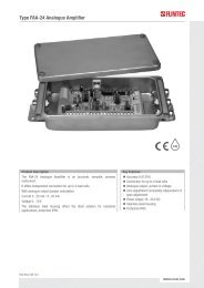
Type <strong>FAA</strong>-<strong>25</strong> Analogue AmplifierProduct DescriptionThe Analogue Amplifier Type <strong>FAA</strong>-<strong>25</strong> is an accurate and economic amplifier,easy to integrate into process control systems.By its “digital heart” the <strong>FAA</strong>-<strong>25</strong> allows a comfortable calibration and setup with a combination of LED’s and push buttons or optionally by PC.The signal output is programmable 0 – 10 V and 4 – 20 mA.Further interfaces are optionally available: 3 opto-isolated digital outputs(2 setpoints, 1 error output), 1 opto-isolated digital input (for zeroing byexternal command) and 1 serial interface RS232.The Analogue Amplifier Type <strong>FAA</strong>-<strong>25</strong> is available in 2 versions:basic version, no optionsversion including interface option (see option)Available AccessorySetup software running under MS Windows (only for version includinginterface option)Key FeaturesLoad cell excitation 5 V DCfor up to 4 load cells à 350 Ω6 Wire load cell connectionAnalogue output 4...20 mA or 0...10 V,selectableDigital filter, switchableNo potentiometer, set up and calibrationvia LED’s and push buttonsPower supply 18...30 V DCDin-rail mountingOptionInterface option:2 setpoints and 1 error output, 1 inputfor zeroing and 1 serial interface RS232for setup and eCal (electronic calibrationwithout test weights)E150-Rev4-GB-1(2)WWW.FLINTEC.COM
SpecificationsINPUT & A/D CONVERTERLinearity0.01 % or betterAnalogue input range 0 mV to 20 mVMin. input range< 1 mVA/D converter24 bit Delta-Sigma ratiometric with integral analog and digital filtersConversion rateUp to 400 measurement values per secondSCALE CALIBRATION & ANALOGUE OUTPUTCalibrationCalibration is performed by test weights using the keys on the front panel. There is no switch or potentiometer for adjustmentin the instrument. Option for electronic calibration without test weights using a PC (interface option required)Digital filter2 step adjustable digital adaptive filterWeighing functions Zeroing via opto-isolated digital input (interface option required)D/A converter16 bitAnalogue outputCurrent output 4-20 mA (at max. 500 Ω load) or voltage output 0-10 V (at min. 10 kΩ load)Set point2 programmable free setpoints (interface option required)LOAD CELLSExcitation5 V DC at 58...1 200 Ω, max. 100 mANumber of load cells Up to 4 units of 350 Ω or 12 units of 1100 ΩConnection4 or 6 wire technique. Cable length 274 m/mm² for 6 wire connection.SETUP & COMMUNICATIONFront panelMembrane keypad including 3x programming keys and 2x LED (Run and Error)PC softwareFor electronic calibration without test weights (interface option required)POWER SUPPLYDC Power supply18...30 V DC, < 200 mAENVIRONMENT AND ENCLOSUREOperation temperature Between -10 °C and +40 °C at 85% RH max, non-condensing.EnclosurePolyamide, for DIN-rail mount, protection class IP20Dimensions45 x 99 x 114 mm; weighs appr. 300 gOPTIONDigital inputs and outputs2 opto-isolated outputs for setpoints, 1 opto-isolated error output (NPN open collector, 18...30 V DC, max. 50 mA),1 opto-isolated input for zeroing and 1 serial interface RS232Dimensions (in mm)E150-Rev4-GB-2(2)Dimensions and specifications are subject to change without notice.WWW.FLINTEC.COM