FlintWeigh Technical Manual V.3.02 GB - Flintec Polska
FlintWeigh Technical Manual V.3.02 GB - Flintec Polska
FlintWeigh Technical Manual V.3.02 GB - Flintec Polska

Create successful ePaper yourself
Turn your PDF publications into a flip-book with our unique Google optimized e-Paper software.
PC-BASED WEIGHING SYSTEM<strong>FlintWeigh</strong>TECHNICAL MANUAL<strong>Flintec</strong> GmbHBemannsbruch 974909 MeckesheimGERMANYwww.flintec.com
Table of Contents:1. Safety Instructions ....................................................................................................................................32. Declaration of Conformity ........................................................................................................................43. Introduction and Block Diagrams ............................................................................................................53.1. Application Range ....................................................................................................................................53.2. Block Diagrams ........................................................................................................................................53.3. Scope of Delivery .....................................................................................................................................63.4. Available Accessoires ..............................................................................................................................64. System Components and <strong>Technical</strong> Characteristics.............................................................................74.1. Type FW-01 Scale Interface ....................................................................................................................74.2. <strong>Technical</strong> Specifications...........................................................................................................................84.3. Important Information about the Operation of Digital Load Cells.............................................................94.4. Information about the Digital Inputs / Outputs..........................................................................................94.5. Operation of Standard Load Cells..........................................................................................................104.6. Sealing Details with Sticker....................................................................................................................104.7. Descriptive Plate ....................................................................................................................................115. nWeigh Software Installation .................................................................................................................125.1. Software Version....................................................................................................................................125.2. Installation ..............................................................................................................................................125.3. nWeigh Files ..........................................................................................................................................136. Weight Display and Control Buttons.....................................................................................................147. nWeigh Configuration .............................................................................................................................157.1. Basic Setup during the Commissioning .................................................................................................157.1.1. Configure the Alibi Memory ............................................................................................................................167.2. Language and other Settings.................................................................................................................177.3. Scale with Standard Load Cells .............................................................................................................187.3.1. Define the Scale Parameters .........................................................................................................................187.4. Scale with Type RC3D Digital Load Cells..............................................................................................197.4.1. Preliminary Note.............................................................................................................................................197.4.2. Define the Scale Parameters .........................................................................................................................197.4.3. Digital Corner Correction................................................................................................................................207.5. Calibrate the Scale.................................................................................................................................217.6. Optional Linearisation of the Scale Curve..............................................................................................227.7. Optional Use of Digital Outputs..............................................................................................................237.7.1. Setpoints and Limit Monitoring .......................................................................................................................237.7.2. Traffic Light Control........................................................................................................................................248. Legal for Trade Operation.......................................................................................................................258.1. EC Type-approval and Test Certificate..................................................................................................258.2. Digital Descriptive Plate .........................................................................................................................258.3. Recording of Weight Values in the Alibi Memory...................................................................................258.4. Show Alibi Memory ................................................................................................................................268.5. Logbook..................................................................................................................................................268.6. Obligations with Legal for Trade Scales ................................................................................................278.7. Legal for Trade Data within the Scale Interface.....................................................................................279. Error Messages........................................................................................................................................2810. OLE Programming Interface...................................................................................................................2910.1. OLE Functions....................................................................................................................................2910.2. Application Example ...........................................................................................................................32<strong>FlintWeigh</strong> <strong>Technical</strong> <strong>Manual</strong>, Rev. 3.02 January 2011 Page 2 of 32
RIGHTS AND LIABILITIESAll rights reserved.No part of this publication may be reproduced, stored in a retrieval system, or transmitted in any form or by anymeans, mechanical, photocopying, recording, or otherwise, without the prior written permission of <strong>Flintec</strong>GmbHNo patent liability is assumed with respect to the use of the information contained herein. While everyprecaution has been taken in the preparation of this book, FLINTEC assumes no responsibility for errors oromissions. Neither is any liability assumed for damages resulting from the use of the information containedherein.The information herein is believed to be both accurate and reliable. FLINTEC, however, would be obliged to beinformed if any errors occur. FLINTEC cannot accept any liability for direct or indirect damages resulting fromthe use of this manual.FLINTEC reserves the right to revise this manual and alter its content without notification at any time.Neither FLINTEC nor its affiliates shall be liable to the purchaser of this product or third parties for damages,losses, costs, or expenses incurred by purchaser or third parties as a result of: accident, misuse, or abuse ofthis product or unauthorized modifications, repairs, or alterations to this product, or failure to strictly comply withFLINTEC operating and maintenance instructions.FLINTEC shall not be liable against any damages or problems arising from the use of any options or anyconsumable products other than those designated as Original FLINTEC Products.NOTICE: The contents of this manual are subject to change without notice.Copyright © 2010-2011 by <strong>Flintec</strong> GmbH, 74909 Meckesheim, Bemannsbruch 9, Germany1. Safety InstructionsCAUTION READ this manual BEFORE operating or servicing this equipment. FOLLOW theseinstructions carefully. SAVE this manual for future reference. DO NOT allow untrained personnel tooperate, clean, inspect, maintain, service, or tamper with this equipment. ALWAYS DISCONNECTthis equipment from the power source before cleaning or performing maintenance. CALL FLINTECENGINEERING for parts, information, and service.WARNING ONLY PERMIT QUALIFIED PERSONNEL TO SERVICE THIS EQUIPMENT.EXERCISE CARE WHEN MAKING CHECKS, TESTS AND ADJUSTMENTS THAT MUST BEMADE WITH POWER ON. FAILING TO OBSERVE THESE PRECAUTIONS CAN RESULT INBODILY HARM.WARNING FOR CONTINUED PROTECTION AGAINST SHOCK HAZARD CONNECT TOPROPERLY GROUNDED OUTLET ONLY. DO NOT REMOVE THE GROUND PRONG.WARNINGSERVICING.DISCONNECT ALL POWER TO THIS UNIT BEFORE REMOVING THE FUSE ORWARNING BEFORE CONNECTING/DISCONNECTING ANY INTERNAL ELECTRONICCOMPONENTS OR INTERCONNECTING WIRING BETWEEN ELECTRONIC EQUIPMENTALWAYS REMOVE POWER AND WAIT AT LEAST THIRTY (30) SECONDS BEFORE ANYCONNECTIONS OR DISCONNECTIONS ARE MADE. FAILURE TO OBSERVE THESEPRECAUTIONS COULD RESULT IN DAMAGE TO OR DESTRUCTION OF THE EQUIPMENT ORBODILY HARM.CAUTIONDEVICES.OBSERVE PRECAUTIONS FOR HANDLING ELECTROSTATIC SENSITIVE<strong>FlintWeigh</strong> <strong>Technical</strong> <strong>Manual</strong>, Rev. 3.02 January 2011 Page 3 of 32
2. Declaration of Conformity0 EG-KonformitätserklärungEC-Declaration of ConformityMonat/Jahr: month/year: 12/2010Hersteller: Manufacturer:<strong>Flintec</strong> GmbHAnschrift: Address: Bemannsbruch 9D-74909 MeckesheimDeutschland / GermanyProduktbezeichnung: Product name:<strong>FlintWeigh</strong> PC-Wägesystem / PC-based Weighing SystemDas bezeichnete Produkt stimmt mit folgenden Vorschriften der Europäischen Richtlinien überein:This product confirms with the following regulations of the Directives of the European CommunityRichtlinie 2004/108/EG des EuropäischenParlaments und des Rates vom 15. Dezember 2004zur Angleichung der Rechtsvorschriften derMitgliedstaaten über die elektromagnetischeVerträglichkeit und zur Aufhebung der Richtlinie89/336/EWGRichtlinie 2006/95/EG Niederspannungs-RichtlinieDie Absicherung aller produktspezifischenQualitätsmerkmale erfolgt auf Basis eines zertifiziertenQualitätsmanagement-Systems nach DIN ISO 9001.Diese Erklärung bescheinigt die Übereinstimmung mitden genannten Richtlinien, beinhaltet jedoch keineZusicherung von Eigenschaften.Directive 2004/108/EC of the European Parliament and of theCouncil of 15th December 2004 on the approximation of thelaws of the Member States relating to electromagneticcompatibility and repealing Directive 89/336/EECDirective 2006/95/EC Low Voltage DirectiveAll product-related features are assured by a qualitysystem in accordance with ISO 9001.This declaration certifies the conformity with the listeddirectives, but it is no promise of characteristics.Folgende Normen werden zum Nachweis der Übereinstimmung mit den Richtlinien eingehalten:As a proof of conformity with the directives following standards are fulfilled:EN 61326-1 Elektrische Mess-, Steuer-, Regel- und Laborgeräte - EMV-Anforderungen - Teil 1: AllgemeineAnforderungen (IEC 61326-1:2005)Electrical equipment for measurement, control and laboratory use - EMC requirements - Part 1: Generalrequirements (IEC 61326-1:2005)EN 60950-1 Einrichtungen der Informationstechnik - Sicherheit - Teil 1: Allgemeine Anforderungen (IEC 60950-1:2005, modifiziert);Information technology equipment - Safety - Part 1: General requirements (IEC 60950-1:2005 modified)<strong>FlintWeigh</strong> <strong>Technical</strong> <strong>Manual</strong>, Rev. 3.02 January 2011 Page 4 of 32
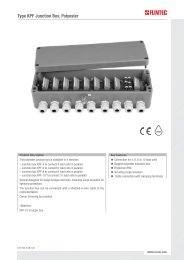
3. Introduction and Block DiagramsThe W&M approved type FW-01 Scale Interface is the key component to integrate a Weighing System into yourPC. <strong>FlintWeigh</strong> does not require any separate weight display and the scale interface assures, that the weightdata will be reliably processed in the PC.It is possible to connect up to 2 scales (up to 16x type RC3D digital load cells respective 2x type LDU digitalamplifiers) via RS485 to the scale interface, which will be connected to the PC via USB interface.When the scales are based on standard load cells you can select among several LDU types which may beplugged into socket within the KAL-4 junction box. The selection of the applied LDU will be defined by therequirements for the weighing application. The technical characteristics of the LDU types and connectiondetails about digital and standard load cells you can find in chapter 4.3.1. Application RangeFor protecting the consumers all scales which are used for commercial transactions (legal for tradeapplications) have to be calibrated in a standardized way. Typical legal for trade scales are retail scales inshops. Privately used bathroom scales or kitchen scales are examples for scales which don’t require anapproved calibration.Legal for trade applicationsThe weighing terminal has an EC type approval which covers standard load cells and scales of the accuracyclass and .All load cells have to keep the tolerances according "OIML R60, Metrological regulation for load cells, Edition2000".For selecting the proper weighing module in legal for trade applications, it is required to verify the compatibilityof modules for the weighing instrument (see file KOMPMODENG.XLS on the <strong>Flintec</strong> CD-ROM).For further information about software, alibi memory and legal for trade applications see chapter 4.Industrial applicationsAll scale connections in industrial applications fall within the responsibility of the scale operator. In suchapplications an approved alibi memory is not available.3.2. Block DiagramsDigital Load CellsType FW-01Scale InterfaceKPFD-8Alibi memory12 V DC SupplyDigital I/OFig. 3.1: Connection of RC3D digital load cells via KPFD-8 junction box<strong>FlintWeigh</strong> <strong>Technical</strong> <strong>Manual</strong>, Rev. 3.02 January 2011 Page 5 of 32
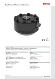
Type FW-01Scale InterfaceStandard Load CellsKAL-4Alibi memory12 V DC SupplyDigital I/OFig. 3.2: Connection of standard load cells via KAL-4 junction box with integrated LDUStandard Load CellsKAL-4Type FW-01Scale InterfaceAlibi memory12 V DC SupplyDigital I/OKAL-4Standard Load CellsFig. 3.3: Block diagram with standard load cells and 2 scales3.3. Scope of Delivery►►►►►Type FW-01 Scale InterfaceSuitable plug connectors for the load cells and the digital I/OnWeigh SoftwareThis manualA medium (CD-ROM) with the nWeigh software, the technical manual, the test certificates of the LDUs,the nWeigh EC type approval, some examples for using the OLE functions and a template for thescale’s descriptive plate in RTF format3.4. Available Accessoires►►►Type KPFD-8 junction box for type RC3D digital load cellsType LDU 68.1 / 68.2 / 69.1 / 78.1 digital amplifiers for standard load cellsType KAL-4 digital junction box<strong>FlintWeigh</strong> <strong>Technical</strong> <strong>Manual</strong>, Rev. 3.02 January 2011 Page 6 of 32
4. System Components and <strong>Technical</strong> Characteristics4.1. Type FW-01 Scale InterfaceFig.4.1 Scale interface, connector sideCalibration lockFig.4.2 Scale Interface; calibration lock (will be sealed in legal for trade applications)DigitalInput/OutputDigitalLoad cellsSupply 12 V DCUSBFig.4.3 Scale Interface; connectors- Digital load cell connector suitable for connecting RC3D load cells or one/two units of LDU xx.x inhalf-duplex mode, see LDU xx.x manual- External 12 V supply required for powering the digital load cells / LDU units<strong>FlintWeigh</strong> <strong>Technical</strong> <strong>Manual</strong>, Rev. 3.02 January 2011 Page 7 of 32
4.2. <strong>Technical</strong> SpecificationsGENERALScale interfaceIntelligent interface with non-volatile memory for system parameters andcalibration dataACCURACYAccuracy ClassIII10 000 intervals (single interval) or n x 3 000 intervals (multi range / multiEU Type approvedinterval)Approval no. D-10-09-024 from 09th August 2010DISPLAY AND KEYBOARDDisplayApproved PC-based weighing system with weight display on PC monitor(Active-X-Control)ResolutionSelectable up to 99 000 counts (in accordance with the regulations)Status annunciators Net mode, No Motion, Max. and Min, e, Scale no.KeyboardThe standard PC keyboard is usedINTERFACE TO DIGITAL LOAD CELLSCommunication & ProtocolRS485 half-duplex, baud rate 9 600…38 400; E7,1 OR 8N,1; compatible withtype RC3D load cell respective type LDU xx.x load cell digitizing unitExcitation12 V DC, max. 450 mAUp to 10 pieces directly powered type RC3D digital load cells ORNo. of load cells / load celldigitizing unitsup to 16 pieces externally powered type RC3D digital load cells ORup to 2 pieces directly powered type LDU xx.x load cell digitizing units(valid for one scale interface)Load cell connection4-wire technique,2 wires for the digitale interface and 2 wires for the sensor supplySCALE CALIBRATION AND FUNCTIONSNo. of scalesUp to 2 scales per scale interfaceWith type RC3D it’s possible to have a 2-deck weighbridge systemCalibrationCalibration performed by nWeigh softwareCorner correctionDigital corner correction (only with type RC3D load cells)Weighing functions Zero, tare, gross, motion detection, automatic zero tracking (Active-X-Control)COMMUNICATIONTo PC USB 2.0DIGITAL INPUTS / OUTPUTSOutput2x opto-isolated for setpoints (Open collector, 24 V DC, 50 mA)Input1x opto-isolated, 24 V DCPOWERPower requirements12 V DC / max. 1.5 A; power consumption depends on number of connectedload cells / load cell digitizing unitsENVIRONMENT AND ENCLOSUREOperating temperature -10…+40 °CStorage temperature -10…+70 °CHumidity40 to 90% RH (non-condensing)EMCAccording to OIML R 76 and EN 45501 requirementsEnclosureAluminium housing (IP 40), installed in the direct vincinity of the PC systemPC SYSTEMRequirementsWindows XP; 1024 x 768 or higher graphic resolution; 128 MB or more RAM,512 MB or more harddisk memory, USB 2.0 Interface<strong>FlintWeigh</strong> <strong>Technical</strong> <strong>Manual</strong>, Rev. 3.02 January 2011 Page 8 of 32
4.3. Important Information about the Operation of Digital Load CellsThe connection of the digital load cells has to be done according the description in the KPFD-8 manual (see<strong>Flintec</strong>-CD, technical documents, manuals).It is allowed to connect up to 16 digital load cells (e.g. type RC3D) to the scale interface.IMPORTANT: If you connect more than 10 digital load cells, then it is mandatory to power all load cells from anexternal power supply.External power supply for digital load cellsThe external power supply has to provide a stabilized +12 V DC / ±5% with at least 1.5 A current. The inputgoes directly to the connection cable of the digital load cells. Only the pins "RS485 A", "RS485 B" and "GND"will be connected with the scale interface.Weighing terminalExternal power supply+12V DC / 1.5 ADigital load cellsWeighingsystem controllerJunctionboxFig. 4.4: Schematic of the external power supply to the digital load cells4.4. Information about the Digital Inputs / OutputsThe digital I/O connections (one input, two outputs) can be used connecting e.g. a traffic light, a gate or aswitch-key.Digital output:Digital input:2x, open collector (max. 24 V DC, max. 50 mA)1x, opto-isolated, 3...24 V DC, max. 20 mA; min. switching current = 1,5 mAPin 6Pin 2Pin 1Pin 5Pin 7Pin 8Fig. 4.5 : Wiring example for the digital I/O<strong>FlintWeigh</strong> <strong>Technical</strong> <strong>Manual</strong>, Rev. 3.02 January 2011 Page 9 of 32
4.5. Operation of Standard Load CellsThe scale interface can be connected with up to two LDU amplifiers. Depending on the application – legal fortrade scale or industrial application – it can be selected among various weighing modules.Weighing module type LDU 68.1 LDU 69.1 LDU 78.1 LDU 68.2Accuracy classNot approvedCertificate no.DK0199-R76-10.04DK0199-R76-03.01 Rev. 2DK0199-R76-10.08 Rev. 1Intervals "n" acc. Kompmodeng: n ind 10.000 10.000 10.000Internal resolution ± 130 000 > ± 1 000 000 ± 260 000 ± 130 000Approved single range scale yes yes yes* noApproved multi range scale no yes yes* noApproved multi interval scale no yes yes* noLoad cell excitation U EXC 5 V DC 5 V AC 5 V DC 5 V DCMinimum input voltage U MIN 0 V 0 V 0 V 0 VApproved min. input per vsi ∆U min 1.0 μV 0.1 μV 0.3 μVInput sensitivity 0.05 μV/d 0.02 μV/d 0.05 μV/d 0.1 μV/dMin. load cell impedance R Lmin 87.5 Ω 250 Ω 87.5 Ω 87.5 ΩMax. load cell impedance R Lmax 1150 Ω 1200 Ω 1150 Ω 1150 ΩMin. operation temperature T min -15 °C -15 °C -15 °C -15 °CMax. operation temperature T max +55 °C +50 °C +55°C +55 °CFractional error limit P ind 0.5 0.5 0.5Load cell connection 4-/6- wire technique 4/6 4/6 4/6 4/6* the nWeigh EC type approval references an old LDU 78.1 certificate no.Tab. 4.3: <strong>Technical</strong> characteristics of LDU amplifiersThe connection of the standard load cells has to be done as described in the manual of the KAL-4 digitaljunction box (see <strong>Flintec</strong>-CD, technical documents, manuals).4.6. Sealing Details with StickerThe legal for trade operation requires a sealing of the junction boxes. The following figure shows a possiblepositioning of the sticker for KAL-4Fig. 4.6: Sealing details with sticker<strong>FlintWeigh</strong> <strong>Technical</strong> <strong>Manual</strong>, Rev. 3.02 January 2011 Page 10 of 32
4.7. Descriptive PlateThe descriptive plate has to be placed on the weighing terminal’s enclosure. It must coincide with the digitaldescriptive plate within the nWeigh software.The descriptive plate supplies following information:► Owner and number of the EC type approval► Version no. of the software incl. revision no./ check sum► Serial no. of the built-in weighing system controller► Type and serial no of the LDUs► Year of manufacture► Traceable access counter (TAC)► Metrological symbol “M”► Interval, min.load and max. load of the scaleFig. 4.7: Descriptive plate of the weighing terminalHint: You can find a template for the scale’s descriptive plate in RTF format on the <strong>Flintec</strong> CD-ROM.<strong>FlintWeigh</strong> <strong>Technical</strong> <strong>Manual</strong>, Rev. 3.02 January 2011 Page 11 of 32
5. nWeigh Software InstallationThe nWeigh software displays the continuously measured weight value of the weighing system controller withina graphical window in a legal for trade quality.nWeigh also provides an OLE interface. External programmes can access the data and information withinnWeigh by using OLE functions. All windows and control buttons are part of the OLE interface.By configuring two digital outputs and one digital input it is possible to implement a simple limit monitoring ortraffic light control.5.1. Software VersionThe software version is defined as follows:NWxyF.exe with x = Main version no.and y = Revision no.e.g.: NW11F.exe Main version no. 1, Rev. no. 15.2. InstallationIt is not required to install the nWeigh software in the conventional way. Just copy from the <strong>Flintec</strong>-CD to adirectory of your choice on a target PC of your choice:► The directory “USB Driver 2008“ (Windows 7 / Vista) respective “USB Driver 2006“ (Windows XP);these driver files are required to install the scale interface via USB connection► the files "NW11F.exe" and " nxWeigh.dll"Fig. 5.1 : Software source directory on the <strong>Flintec</strong> CDFig. 5.2 : Software target directory on the installation PCHint: Your profile as a Windows user requires writing preferences for this installation directory. In this directoryfurther configuration files will be created (see chapter 5.3).Then you connect the scale interface to an USB port of the installation PC. Hereby the installation PCautomatically detects the scale interface and the operating system will search for a suitable device driver, whichyou can find in the directory “USB Driver 2008“ (Windows 7 / Vista) resp. “USB Driver 2006“ (Windows XP).After the successful driver installation the Windows device manager should list the <strong>FlintWeigh</strong> scale interface inthe section “Connections (COM & LPT)“ listen. Please note the assigned COM port no. for further use duringthe commissioning.When started for the first time nWeigh should start with the language setting "English" (see chapter 8.2).<strong>FlintWeigh</strong> <strong>Technical</strong> <strong>Manual</strong>, Rev. 3.02 January 2011 Page 12 of 32
5.3. nWeigh FilesIn the nWeigh software directory you can find the following files (some files may be hidden or protected andtherefore not visible):NW11F.EXENW10.KEYNW10.ININW10.LIMNW10xx.CFGnWeigh main programme; can be used directly (EXE file) as weight display or for serviceand calibration purposes. In weighing mode the main programme can communicate toapplication programmes via its integrated OLE interface. If the OLE interface is in use thenWeigh software automatically starts in the weighing mode.This file will be created during the commissioning. It contains non-approved parameters andsettings like COM port, baud rate, remote display, language, filter settings, zero tracking,etc.This file will be created during the commissioning. It contains the path information to thestorage location of the alibi data.This file will be created during the commissioning. It contains the manual settings of thedigital outputs (setpoints).This file will be created during the commissioning. For diagnosis purposes it contains copiesof the calibration data, which are stored in the approved memory of the weighing systemcontroller.Following files may be located in the nWeigh software directory or somewhere else (see data memoryServer):NW10.CNTRecord counter (for multi scale systems), protected by CRC16 checksumNWmmjj.MEMAlibi memory files, divided by month (mm = month, yy = year), protected by CRC16checksum<strong>FlintWeigh</strong> <strong>Technical</strong> <strong>Manual</strong>, Rev. 3.02 January 2011 Page 13 of 32
6. Weight Display and Control ButtonsThe various functions will be described below.Fig. 7.1 : Weight display and control buttons(1) Display window "nWeigh"(2) Logo(3) Software version and checksum(4) Weight value(5) Weight unit*(6) Service functions(7) Displayed scale (no.) and select scale(8) Zeroing the selected scale(9) Taring the selected scale(10) Operation mode of the selected scale(11) “Print” (record) to alibi memory(12) Alibi memory*Unit in black letters: scale is calibratedUnit in grey letters: scale has no valid calibrationService functions: the window "nWeigh Settings” opens (6)In the weighing mode via the OLE interface only the window “Information“ will be opened.It’s not possible to set up anything.Displayed scale (no.) and select scale (7)Currently scale no. 1 is displayed.Other options are:Scale no. 2 is displayedDual scale function, sum of scale no. 1 and no. 2Zeroing the selected scale (8)Zeroing is only allowed for the empty scale. The current load must fall within the definedzeroing range ( -1% to +2% off max. load in legal for trade applications; user-defined rangein industrial applications)Taring the selected scale (9)Taring is only allowed, if the current gros weight is positive and the scale is in no-motioncondition. When clicking this button the scale will be tared (gros net). The next click onthis button will delete the tare weight (net gros).Operation mode of the selected scale (10)A tared scale will display the additional info “NET“.The next click on this button will delete the tare weight (net gros).Scale is stable (no-motion condition)Scale is within the zero setting rangeActive weighing range (1, 2 or 3)“Print” (record) to alibi memory (11)Performs a weighing and saves the corresponding data to the alibi memoryAlibi memory (12)Here you can view and print the contents of the alibi memory<strong>FlintWeigh</strong> <strong>Technical</strong> <strong>Manual</strong>, Rev. 3.02 January 2011 Page 14 of 32
7. nWeigh Configuration7.1. Basic Setup during the CommissioningWhen you commission nWeigh for the first time, following basic setup has to be done: Sensor interface and Sensor type ( standard load cells OR digital load cells) Scale system Data memory Interface to remote display and remote display type Gravitational factor, if applicableThese basic settings will be described in this chapter.Fig. 8.1 Weight display before commissioningStart the main programme ”NW11F.EXE“A click on this button will open the service functions(window "nWeigh Settings").Fig.8.2 Register „Communication“Sensor interface:Sensor type:Scale system:Select the serial interface, which has been assigned to the weighing systemcontroller (see chapter 5.3) and set up the baud rate to „9600“Defines, if standar or digital load cells will be connected(LDU = standard load cells; RC3D,= digital load cells)Defines, if there will be “1 scale“, “2 scales“ (independend from each other) or a“Dual scale”(Dual scale = sum of scale no.1 and scale no.2)Data memory: Location for the alibi memory (see chapter 8.1.1)Remote display:Gravitational factor:Define interface and type as requiredIs only used, if the calibration location and the installation location are notidentical. Otherwise this parameter remains untouched.Default setting: 9.8075656<strong>FlintWeigh</strong> <strong>Technical</strong> <strong>Manual</strong>, Rev. 3.02 January 2011 Page 15 of 32
7.1.1. Configure the Alibi MemoryIn legal for trade applications the recorded weighing results will be stored to an approved data memory, the socalled alibi memory.Fig.8.3 Configure the alibi memoryIn the standard installation the data memory will beautomatically created in the nWeigh programmedirectory.Generally the location for the data memory can beselected freely, e.g. it is allowed to choose anotherlocal directory or any network drive.For changing the memory location click on thefolder sign in the Data memory area.Fig.8.4 Alibi memory in a local directoryFig.8.5 Alibi memory on a network drive<strong>FlintWeigh</strong> <strong>Technical</strong> <strong>Manual</strong>, Rev. 3.02 January 2011 Page 16 of 32
7.2. Language and other SettingsnWeigh has some setup parameters, which can be set up before or after the commissioning. If you haveconfigured a multi scale system, then first select the wished scale (“1” or “2”) in the weight display (Fig. 7.1).Fig. 8.6 Register „Parameters“Selected scaleFilter characteristics:Language:Zero tracking:Zero after power on:Frameless:Filter characteristics for the digital signal processing: Depending on the application thesettling characteristics can be set to “fast“ (shortest settling time), „medium“ (factorysetting) or „slow“ (best averaging)Select as necessary, the selected language will be activated immediatelyEnables / disables the automatic zero tracking in normal weighing mode(automatic zeroing of the display, if the scale is stable and the current weight valuefalls within the zero setting range)Enables / disables the automatic zeroing after software start(automatic zeroing of the display, if the scale is stable and the current weight valuefalls within the zero setting rang)Enables / disables the frameless operation of the softwareIf "Frameless" is enabled, the window will be displayed without title bar and frame inthe operation via OLE communication.Record lock:(the record lock isactive, if the weight unitshows a greybackground)Input (tilt)Zero crossingChanging > 20eEnables the digital input as a recording criteria, e.g. tilt sensor(closed = recording allowed; open = recording locked)If enabled, the scale must be unloaded before a new weighingresult can be recordedIf enabled, the displayed weight has to change by at least 20 ebefore a new weighing result can be recordedPasscode:Here you can define an alphanumeric user-defined password (1 to 8 characters) forprotecting the nWeigh settings from any unauthorized access.If this field is empty, no password will be asked.Attention: Please note your password! If a password is defined you will never getaccess to the scale settings without this password.Output 1:Output 2:The functionality of the digital outputs, e.g. setpoint outputs, normally will be definedafter the scale calibration (see chapter 8.7).<strong>FlintWeigh</strong> <strong>Technical</strong> <strong>Manual</strong>, Rev. 3.02 January 2011 Page 17 of 32
7.3. Scale with Standard Load CellsImportant: The sensor type already has been set to “LDU” (see Fig. 8.2; Register “Communication“).If you have to configure a multi scale system, then select the wished scale no. ("1" or "2") within the weightdisplay (Fig. 7.1).7.3.1. Define the Scale ParametersFig. 8.7 Register ”Calibration“For sensor type “LDU“ andsingle-interval scaleSelected scaleSensor address:Scale type:Defines the address for the LDU (see table below for the factory settings) and enablesthe LDU (by activating the check box besides the input field)Note: The address in parentheses will be used for the second LDU, if two LDUs of thesame type will be used.LDU-Typ Sensor address Comment68.1 1 (2) Legal for trade69.1 3 (4) Legal for trade78.1 5 (6) Legal for trade (see chapter 4.4)68.2 7 (8) Not approvedSettingSingle-intervalMulti-rangeMulti-intervalCommentThe scale has exactly one weighing range with a constant scaleintervalThe scale has 2 or 3 weighing ranges with different scale intervals. Ifthe current gros value of the measured weight falls within the nextweighing range and larger scale interval (changeover threshold 1 and2), then the larger scale interval remains active until the scale will beunloaded and will return to the zero point.The scale has 2 or 3 weighing ranges with different scale intervals.The current gros value of the measured weight determines the activeweighing range and the active scale interval at any time.Scale interval 1/2/3: Step size of the display resolution for the scale respective the weighing rangeDecimals:Unit:No-motion range /period:Number of digits after the decimal pointWeight unit for the displayed weight: g, kg, t or lbCondition for a stable scale (no. of scale intervals, no. of measured values);Default: 2d and 10 values in legal for trade applications; in industrial applications thesecriteria may be modifiedMax. capacity: Maximum load of the scale (as a multiple of the scale interval e1)<strong>FlintWeigh</strong> <strong>Technical</strong> <strong>Manual</strong>, Rev. 3.02 January 2011 Page 18 of 32
Min. capacity: Minimum load of the scale (as a multiple of the scale interval e1)Test weight: Weight of the calibration weight (as a multiple of the scale interval e1)Changeoverthreshold 1/2:Only for multi-range / multi-interval scales:Transition points for range or interval (as a multiple of the scale interval e1)Important: For saving all scale parameter settings you have to close the window “nWeigh Settings” afterwards.Now the weight display (Fig. 7.1) should show a random value.The next step is the calibration of the scale (see chapter 8.5).7.4. Scale with Type RC3D Digital Load CellsImportant: The sensor type already has been set to “RC3D” (see Fig. 8.2; Register “Communication“).If you have to configure a multi scale system, then select the wished scale no. ("1" or "2") within the weightdisplay (Fig. 7.1).7.4.1. Preliminary NoteThe next figure shows the basic principles of addressing the load cells in a weighbridge / vehicle scale. Theshown numbering simplifies the corner correction (chapter 8.4.3).EntranceEinfahrt1 (A)3 (C)5 (E)7 (G)9 (I)Ausfahrt Exit2 (B)4 (D)6 (F)8 (H)10 (J)Fig. 8.8 Addressing load cells in a weighbridge / vehicle scale7.4.2. Define the Scale ParametersFig.8.9 Register ”Calibration“for sensor type “RC3D“ and Single-interval scaleFig.8.10 RC3D Load cellsSensor-Adresse:After activating the check box “enable” and clicking the button “RC3D“ the window“RC3D Load Cells“ will be opened (see Fig. 8.10).Here you select the load cells by their addresses (A, B, C, etc.). The serial numbers willbe read and displayed automatically.If one or more address fields should have a red background, then the communication tothis/these load cell(s) is not OK. The corresponding load cells have to be checked(address, protocoll, load etc.)<strong>FlintWeigh</strong> <strong>Technical</strong> <strong>Manual</strong>, Rev. 3.02 January 2011 Page 19 of 32
Scale type:SettingSingle-intervalMulti-rangeMulti-intervalCommentThe scale has exactly one weighing range with a constantscale intervalThe scale has 2 or 3 weighing ranges with different scaleintervals. If the current gros value of the measured weight fallswithin the next weighing range and larger scale interval(changeover threshold 1 and 2), then the larger scale intervalremains active until the scale will be unloaded and will return tothe zero point.The scale has 2 or 3 weighing ranges with different scaleintervals. The current gros value of the measured weightdetermines the active weighing range and the active scaleinterval at any time.Scale interval 1/2/3: Step size of the display resolution for the scale respective the weighing rangeDecimals:Unit:No-motion range /period:Number of digits after the decimal pointWeight unit for the displayed weight: g, kg, t or lbCondition for a stable scale (no. of scale intervals, no. of measured values);Default: 2d and 10 values in legal for trade applications; in industrial applications thesecriteria may be modifiedMax. capacity: Maximum load of the scale (as a multiple of the scale interval e1)Min. capacity: Minimum load of the scale (as a multiple of the scale interval e1)Test weight: Weight of the calibration weight (as a multiple of the scale interval e1)Changeoverthreshold 1/2:Only for multi-range / multi-interval scales:Transition points for range or interval (as a multiple of the scale interval e1)Important: For saving all scale parameter settings you have to close the window “nWeigh Settings” afterwards.Now the weight display (Fig. 7.1) should show a random value.The next step is the digital corner correction (see chapter 8.4.3).7.4.3. Digital Corner CorrectionImportant: After the digital corner correction the scale always requires a new calibration.Fig.8.11 RC3D Load cellsEach corner (load cell) will be loaded one after the other with acalibration weight (the calibration weight should be at least 10%of max. capacity; better is 30% of max.capacity).Using the slider the display value of the loaded load cell will becorrected until the displayed value equals the calibrationweight.The corner correction doesn’t depend on the sequence of theloaded load cell, but a systematic course may spare time andminimises the risk for errors (see chapter 8.4.1).Hint: It may be meaningful to perform a calibration of the scaleand save the calibration data before the corner correction. Thisoptimises the display characteristics already before the cornercorrection.The next step is always the calibration of the scale (see chapter 8.5)<strong>FlintWeigh</strong> <strong>Technical</strong> <strong>Manual</strong>, Rev. 3.02 January 2011 Page 20 of 32
7.5. Calibrate the ScaleImportant: Before you can calibrate the scale you have to define the basic setup (see chapter 8.1) and thescale parameters (see chapter 8.3 respective 8.4). If you have to configure a multi scale system, then select thewished scale no. ("1" or "2") within the weight display (Fig. 7.1).1. Open the window “nWweigh Settings“2. Open the register “Calibration”3. Unload the scale4. Click the button “Dead load“; this defines thecurrent load status of the scale as the zeropoint. The weight display should show now thevalue “0”.5. The calibration weight will be put on the centreof the scale. The true applied weight (at least10% of max. capacity) has to be entered intothe field “Test weight” (here 2500e = 5 kg).6. Click the button “Gain“; now the correct gainfor the selected scale will be calculated. Theweight display should show now the value ofthe calibration weight.7. For saving the calibration data click the button“Save calibration data”. Now a warningappears which describes the consequences inlegal for trade applications. (“Attention! Aftersaving the claibration data, the internalcalibration counter (TAC) is still countedforward. Afterwards the scale has to be reapprovedby the Calibration Authority!”)8. For confirming the saving click the button“Save”. If you want to keep an existingapproval click the button “Cancel”.9. After the calibration the window “nWeighSettings” has to be closed. This will save allsetup changes.10. The weight display will now show the weight ofthe calibration weight, if the calibration weightstill loads the scale.Hint: After the calibration you have to close the window „nWeigh Settings“ by clicking the button “X“ (upper rightwindow corner). In multi scale applications you may select and calibrate the second scale now.<strong>FlintWeigh</strong> <strong>Technical</strong> <strong>Manual</strong>, Rev. 3.02 January 2011 Page 21 of 32
7.6. Optional Linearisation of the Scale CurveThe standard scale calibration may be supplemented by a linearisation with up to 5 correction points. Herebythe correction points have to be in a stricly increasing order, which is:Min. capacity < Point 1 < Point 2 < Point 3< Point 4 < Point 5 < Max. capacity of the scaleImportant: Before any linearisation you have to define the basic setup (see chapter 8.1), the scale parameters(see chapter 8.3 respective 8.4) and you have to calibrate the scale (see chapter 8.5). If you have to configurea multi scale system, then select the wished scale no. ("1" or "2") within the weight display (Fig. 7.1).1. Open the window “nWweigh Settings“2. Open the register “Linearisation“3. Correction point 1: A calibration weight will beput on the centre of the scale. The true appliedweight as a multiple of the scale interval e hasto be entered. Then you use the slider to correctthe display value until it equals the calibrationweight4. Define correction point 2, if applicable (this isdone like correction point 1 but uses a higherweight)5. Define further correction points, if applicable6. 7. For saving the calibration data click thebutton “Save calibration data”. Now a warningappears which describes the consequences inlegal for trade applications. (“Attention! Aftersaving the claibration data, the internalcalibration counter (TAC) is still countedforward. Afterwards the scale has to be reapprovedby the Calibration Authority!”)7. For confirming the saving click the button“Save”..Hint: After the linearisation you have to close the window „nWeigh Settings“ by clicking the button “X“ (upperright window corner). In multi scale applications you may select and correct the second scale now.<strong>FlintWeigh</strong> <strong>Technical</strong> <strong>Manual</strong>, Rev. 3.02 January 2011 Page 22 of 32
7.7. Optional Use of Digital OutputsAfter opening the service functions (window "nWeigh Settings") and selecting the register “Parameters“, youcan assign a functionality to the digital outputs:Fig.8.11 Register “Parameters“for defining the digital outputsStep 1: Select the source to control the outputAllowed settings are Scale 1, Scale 2 andCombination.Step 2: Assign a functionality to the outputAllowed settings are:Setting Function“Off“ Without“Limit“ Limit monitoring (see chapter 8.7.1)“Traffic light“ Traffic light control (see chapter8.7.2)7.7.1. Setpoints and Limit MonitoringFig.8.12 Example for the limit monitoring1. Select the scale as the source2. Select the function “Limit“3. Define the weight value as a multiple of intervale; if the output shall follow the “Net value”, thenactivate the associated check box4. The output will be switched, if the “weight value< Limit“. If the output shall show an inverselogic, then activate the associated check box“Exceeded”5. By activating the check box “Input” you may usethe digital input as an additional switchingcriteria for the limit monitoring: the setpointoutput will only be activated, if the digital input isactive, too<strong>FlintWeigh</strong> <strong>Technical</strong> <strong>Manual</strong>, Rev. 3.02 January 2011 Page 23 of 32
7.7.2. Traffic Light ControlThe implementation of a traffic light control requires following setup:1. Define the function “Limit“ for digital output 12. Define the function “Traffic Light” for digital output 23. The setpoint values for both outputs have to be defined to the same value in such a way, that thesystem can reliably detect an “Empty scale”A functional setup switches the outputs as follows (vehicle scale example):Action/StatusOutput 1Output 2Entrance Exit(“Empty”)(Weighing finalised)Empty scale A1 = 1 Green Red A2 = 0Vehicle is on the scale A1 = 0 Red Red A2 = 0Weight recorded A1 = 0 Red Green A2 = 1Empty scale A1 = 1 Green Red A2 = 0<strong>FlintWeigh</strong> <strong>Technical</strong> <strong>Manual</strong>, Rev. 3.02 January 2011 Page 24 of 32
8. Legal for Trade Operation8.1. EC Type-approval and Test CertificateSee documents on the <strong>Flintec</strong> CD.8.2. Digital Descriptive PlateThe digital descriptive plate will be displayed after opening the service functions (window "nWeigh Settings")and selecting the register „Information“:Fig. 9.1 Digital descriptive plateThe digital descriptive plate must conform to the physicaldescriptive plate.(1) Version and revision of the software, checksum inlegal for trade applications in parentheses(2) Hint area in non-approved applications(3) Metrological symbol "M": green = approved, red = notapproved(4) No. of EC type-approval(5) Electronic calibration counter "TAC"(6) Logo and address of the owner of the EC typeapproval(7) Parameters of the selected scale(8) Parameters of the weighing system controller and theLDUsHere you can also enable the 10-times higher resolutiondisplay mode.8.3. Recording of Weight Values in the Alibi MemoryFig. 9.2 Successful recording of weight valuesClick the buttonwithin the weight displayThe window „Information“ will be opened:Here the record no. and the weight value to record will bedisplayed.For transfering them into the alibi memory click the “OK“ button.Fig. 9.3 Prevented recording of weight valuesIf the error message „Recording is not possible“ appears, thenthe scale was in motion or any of the enabled record locks (seeregister „Parameters“) has prevented the successful recording.<strong>FlintWeigh</strong> <strong>Technical</strong> <strong>Manual</strong>, Rev. 3.02 January 2011 Page 25 of 32
8.4. Show Alibi MemoryFig. 9.4 Show alibi memoryClick the buttonwithin the weight displayThe window „nWeigh long-time memory“ will beopened.Figure 9.5 Main window of the alibi memoryFirst select the month and year of the time period todisplayIf necessary it is also possible to display archivedalibi data: search for the path to the file(“NWxxxx.MEM”*) and afterwards click the button“Show long-time memory”.Contents of the long-time memory: COM port no.,scale no., record no., date and time, weight, scalestatus and tare weight where applicable.If you click the button “Print” the contents of thelong-time memory will be printed.*incl. path and file name e.g. C:\nWeigh\NW0510.MEM8.5. LogbookFig. 9.6 Show logbookOpen service functionsFig. 9.7 Main window of the LogbookSelect register “Logbook”Here you can view all changes which are relevantfor the legal for trade operation (e.g. calibrations,updated software version, etc.).Hint:The amount of logbook entries is limited to 200.<strong>FlintWeigh</strong> <strong>Technical</strong> <strong>Manual</strong>, Rev. 3.02 January 2011 Page 26 of 32
8.6. Obligations with Legal for Trade ScalesThe operator is responsible for the first and all regularly recurrent official calibrations.Important: The official seal may only be broken by authorized qualified staff.If one or more of the following changes has happened, the operater has to send a written note to the assignedpublic authority and a new official calibration is mandatory:► Broken seals► Replaced load cells► Replaced load carrier► Replaced wiring► Replaced LDUs► Replaced weighing system controller► Replaced descriptive plate► Calibration of the scale► Changes to the approved software settingsHint: The user is responsible for the correct performance of any official calibration.8.7. Legal for Trade Data within the Scale InterfaceIn legal for trade and industrial applications all calibration data will be stored in a flash memory in the scaleinterface. These data can only be accessed, if the authentification of the nWeigh-Software to the scale interfaceis valid. If these data will be saved during a calibration, the electronic calibration counter (TAC) willautomatically increased by one. The stored data is the following:Structure of the general scale dataSerial no.Up to 17x per controller; up to 16x type RC3D digital load cell respective LDUGravitational factor Default value: 9.8075656Calibration counterProgramme version x._Programme revision _.xCorner correction Max. 16 data records for up to 16x type RC3D digital load cellChecksum EXE CRC16 for complete programme codeChecksumCRC16 for general scale dataStructure of the individual scales (3x for Scale 1, Scale 2 and Dual scale)Scale interval3x for up to three rangesDecimalsUnitMin. capacityDefault value: 20eNo-motionCalibration weightMax. capacityMax. capacity + 9e = overloadChangeover threshold 2x per scale (up to 3 ranges per scale)Curve linearisation Up to 5 points per scaleZero point (Dead load pt.)Gain valueScale typeSingle-interval, Multi-range, Multi-intervalChecksumCRC16 for scale dataLogbookLogbook entriesUp to 200; 8 bytes incl. CRC for each<strong>FlintWeigh</strong> <strong>Technical</strong> <strong>Manual</strong>, Rev. 3.02 January 2011 Page 27 of 32
9. Error MessagesWarningsSoftwareCalibrationA new software version is used.Elements of the calibration data have been changed.Important note: If a warning appears, the calibration data have to be saved again. Thereby the internalcalibration counter will be incremented by one which is especially relevant in legal for trade applications.<strong>FlintWeigh</strong> <strong>Technical</strong> <strong>Manual</strong>, Rev. 3.02 January 2011 Page 28 of 32
10. OLE Programming InterfaceThe programming interface to an application programme is executed as an automation (OLE-) server for 32-bitWindows programmes (OLE = Object Linking and Embedding).The communication between any application programme and nWeigh will be done exclusively by the followingfunctions which are described below.10.1. OLE FunctionsFunctionPosition (x,y)Stop()Switch(w)DescriptionPosition the weight display on the desktop ("0,0" belongs to top left corner)Parameter Type Usex Integer Horizontal positiony Integer Vertical positionAttention: It is mandatory to call this function exactly once during the initialisation of theapplication software!Stops communicationAttention: It is recommended to call this function once just before closing the applicationsoftware. This will stop the communication to the weight system controller clearly!Select scale (only for multi scale systems)Parameter Type Usew Integer w = 1 (scale 1); w = 2 (scale 2)w = 3 (dual scale)Zero()SetTare()ClrTare()PreTare(v)ValueTen(t)Zeroing the selected scaleTaring the selected scaleDelete the tare weight of the selected scaleSet the tare weight for the selected scale manuallyParameter Type Usev32-bit Tare value including all decimal places but withoutInteger decimal point ( e.g. 13.25 kg v = 1325)Read the current weight valueReturn valueString, 9 digitsFormat„nnnnnnndd“ withnnnnnnn = weight value including decimal point, 7 digitsdd = weight unit, 2 digitsHint: Unused places within the weight value will be filled with spaces.Weight display with 10-times increased resolution (zoom)Parameter Type Uset Integer zoom off (t = 0) / zoom on (t= 1)<strong>FlintWeigh</strong> <strong>Technical</strong> <strong>Manual</strong>, Rev. 3.02 January 2011 Page 29 of 32
FunctionDescriptionRegist Register the current weight value – Format 1Return valueValue rangeFormat: string, 16 digits:“rrrrrr nnnnnnn dd w” withrrrrrr Record no., 6 digits 000001, 000002, 000003...nnnnnnnWeight value includingdecimal point, 7 digits0...800 000dd Weight unit, 2 digits g, kg, t, lbw Scale no., 1 digit 1 (scale 1); 2 (scale 2); 3 (dual scale)Hint: Unused places within the weight value will be filled with spaces.Attention: In legal for trade operation an entry to the alibi memory will be created and therecord counter will be incremented by one.If a recording is not possible, a 2-digit error code will be notified:E1 Scale in motion E4 No zero crossingE2 Weight value ≤ 0 E5 Open input (tilt)E3 Gros weight < minimum load E6 Overload, etc.Regist2 Register the current weight value – Format 2Return valueValue rangeFormat: string, 30 digits:“w_rrrrrr_nnnnnnn_kk_ttttttt_dd“ withw Scale no., 1 digit 1 (scale 1); 2 (scale 2); 3 (dual scale)rrrrrr Record no., 6 digits 000001, 000002, 000003...nnnnnnnWeight value includingdecimal point, 7 digits0...800 000kk Tare indication„ “ (no tare); „ T“ (normal tare);„PT“ (manual tare entry)tttttttTare value includingdecimal point, 7 digits0...800 000dd Weight unit, 2 digits g, kg, t, lbHint: Unused places within the weight value will be filled with spaces.Attention: In legal for trade operation an entry to the alibi memory will be created and therecord counter will be incremented by one.If a recording is not possible, a 2-digit error code will be notified:E1 Scale in motion E4 No zero crossingE2 Weight value ≤ 0 E5 Open input (tilt)E3 Gros weight < minimum load E6 Overload, etc.Param(w)Read scale parametersParameter Type Usew Integer w = 1 (scale 1); w = 2 (scale 2); w = 3 (dual scale)Return valueValue rangeFormat: string, 17 digits:"w_t_z1_z2_z3_k_dd" withw Scale no., 1 digit 1 (scale 1); 2 (scale 2); 3 (dual scale)t Scale type, 1 digit 1 (single-interval), 2 (multi-range), 3 (multi-interval)z1 Scale interval 1, 2 digits 01, 02, 05, 10, 20, 50z2 Scale interval 2, 2 digits 02, 05, 10, 20, 50 (at single-interval: 01)Z3 Scale interval 3, 2 digits 05, 10, 20, 50 (at single-interval: 01)k Decimal places, 1 digit 1, 2, 3, 4, 5dd Weight unit, 2 digits g, kg, t, lb<strong>FlintWeigh</strong> <strong>Technical</strong> <strong>Manual</strong>, Rev. 3.02 January 2011 Page 30 of 32
FunctionStatus(w)DescriptionRead scale statusParameter Type Usew Integer w = 1 (scale 1); w = 2 (scale 2); w = 3 (dual scale)Return valueFormat: string, 31 digits:"AB_gggggggdd_tttttttdd_nnnnnndd" withValue rangeA Status bit 12 0 (= 1) = No motion2 1 (= 2) = Active tare (net indication)2 2 (= 4) = Zero setting range2 3 (= 8) = Accurate zeroB Status bit 22 4 (= 16) = Error2 0 (= 1) = Zero crossing2 1 (= 2) = Minimum load2 2 (= 4) = Tilt switchgggggggdd Gros value and unit 0...800 000 / g, kg, t, lbtttttttdd Tare value and unit 0...800 000 / g, kg, t, lbnnnnnnndd Net value and unit 0...800 000 / g, kg, t, lbHint: Unused places within the weight value will be filled with spaces.SetOutput(o,w,f,v) Configure digital outputs and setpointsParameter Type Useo 32-bit Integer o = 1 (output 1); o = 2 (output 2)w 32-bit Integer w = 1 (scale 1); w = 2 (scale 2); w = 3 (dual scale)f32-bit IntegerFlag Operation2 001 Fixed setting2 1 02 Setpoint control00 Output not used03 Traffic control2 2 0 (= 0) Under-run1 (= 1) Exceeded2 3 0 (= 0) Gros value1 (= 8) Net value2 4 Status of fixed setting0 (= 0) Off1 (= 16) On2 5 Enabled by input0 (= 0) Off1 (= 32) Onv 32-bit Integer Setpoint including all decimal places but without decimalpoint ( e.g. 13.25 kg v = 1325)All functions are characterised in the type library “NW10.TLB”, which may be included into the programmingenvironment of the application programme.<strong>FlintWeigh</strong> <strong>Technical</strong> <strong>Manual</strong>, Rev. 3.02 January 2011 Page 31 of 32
10.2. Application ExampleExample 1 – Visual Basic:Call of OLE function "Regist" in VB-------------------------------------------------------Dim scale As Object'Create object and position the weight display'(only once in the programme during initialisation)Set scale = CreateObject("scale99.serv")Call scale.Position(0,0)'Recording'(several times during normal operation)print_str = scale.Regist'Stop communication'(only once in the programme before closing)Call scale.Stop-------------------------------------------------------Example 2 - VisualBasicScript / Windows Scripting Host:Call of OLE function "Regist2" in VBS'----------------------------------------------------' Sample programme for use of OLE connection to nWeigh'----------------------------------------------------'## Create Shell-Object ##Set ws = CreateObject("WScript.Shell")'## Create OLE-Object for "nWeigh" ##Set scale = CreateObject("Scale99.Serv")'## First neccesary command to "nWeigh"=position(x,y) ##scale.position 0,0'## Info message and waiting till "nWeigh" is ready ##ws.popup "Wait for initialisation of OLE server" ,1WScript.Sleep (10*1000)'## Show nWeigh window ***scale.Show'## Wait for scale is ready and do recording–format 2 ##Doregist2value = scale.regist2Loop Until (left(regist2value,1)"E")'## Show result of recording – format 2 ##msgbox regist2value'## Stop OLE-Server ##scale.stop'----- End of Sample programme -----www.flintec.com<strong>FlintWeigh</strong> <strong>Technical</strong> <strong>Manual</strong>, Rev. 3.02 January 2011 Page 32 of 32