KEK Manual V.1.00 - Flintec Polska
KEK Manual V.1.00 - Flintec Polska
KEK Manual V.1.00 - Flintec Polska

You also want an ePaper? Increase the reach of your titles
YUMPU automatically turns print PDFs into web optimized ePapers that Google loves.
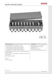
INTRODUCTION AND TECHNICAL DATAThe stainless steel junction box is designed for the parallel connection of up to 4 load cells.Type No. of load cells Housing size Inputs Output<strong>KEK</strong>-4 up to 4 105 x 210 x 40 mm 4x PG9 1x PG9The junction box type <strong>KEK</strong> can be connected to the instrumentation with a shielded 6-wire signal cable.The corner correction is done with resistors and/or potentiometer.Housing material:Protection class:Cable connection:Corner correction:Stainless steelIP65With clamping terminalsBy exchangeable resistorsMECHANICAL INSTALLATIONLook for a mounting location which is more or less dry and protected from environmental stress.ELECTRICAL CONNECTIONSFigure 1: Dimensions in [mm]The connection sequence of the load cells should correspond to the corners of the scale, i.eCorner 1 = Load cell 1, Corner 2 = Load cell 2, etc.LOAD CELL CABLE CONNECTIONFirst the cable gland (see (1) in fig.1) must be loosened. Then you have to feed the load cell cable through thecable gland unless the shrink tube is fully disappeared in the box. The wires have to run below the printedcircuit board and will be pulled back to the top at the upper end of the printed circuit board. Afterwards you canconnect the cables to the clamping terminals as indicated below:Cable coulour Description Terminal designationyellow = Cable shield Shield / Schirmred = Signal – (Output –) red / rotwhite = Signal + (Output +) white /weissblack = Excitation – (Input –) black / schwarz(if applicable, brown)* = Sense – black / schwarzgreen = Excitation + (Input +) green / grün(if applicable, blue)* = Sense + green / grün* if load cell is equiped with 6-wire conductor cableJunction Box Type <strong>KEK</strong> – Technical <strong>Manual</strong>, Rev. 1.00 August 2007 Page 3 of 4
After all conductors have been clamped to the terminals, the cable glands must be tightened. Please verifythat all cable glands are tight and the cable is fully stress relieved.OUTPUT CABLE CONNECTIONThe signal cable (connection between junction box and the following electronics) should be a 6 – wireshielded cable and has to be kept as short as possible. Depending on type and manufacturer signal cablesmay have different colours. Therefore make your own choice.Cable colour, example Description / Terminal designationouter cable screen= Shieldpink = Signal – (Output –)white = Signal + (Output +)grey = Sense –brown = Excitation – (Input –)yellow = Sense +green = Excitation + (Input +)CORNER CORRECTION AT SCALES WITH FLINTEC LOAD CELLS<strong>Flintec</strong> load cells are manufactured with rather tight tolerances, so in most cases an additional cornercorrection is not required. The best conditions are achieved if you use load cells of the same class(Designation is done with capital letters A to I on the load cell package besides the type label).Hint: Corner errors can have a mechanical background, e.g. sloped mounting surface of the load cell.Procedure:1. The 0 Ohm jumpers instead of the correction resistors must be in place (shipment status).2. Get the display value for each corner. Use the highest possible display resolution (e.g. factor 10 or higher)or, if this is not possible, measure the the digital weight increment using corresponding weights.3. The corner with the lowest display value is the starting point for the corner correction. The differences ofthe other corners are calculated with reference to this “basic corner”.4. Calculate the correction resistance as follows:Correction resistance [Ω] =Deviation in [kg]Test load in [kg]X Input resistance of the load cell [Ω] ** 1100 Ω input resistance for: BK2, SB4, SB5, SB6, SB14, SLB, ZLB, UB1, UB5, UB6, PB, RC3400 Ω input resistance for: RC1, SB2Example 1: 1100 Ω load cell0.1 kg corner error with 500 kg test loadExample 2: 400 Ω load cell10 kg corner error with 5000 kg test load0.1 kg500 kg10 kg5000 kgx 1100 Ω =x 400 Ω =0.22 Ω0.8 Ω5. Install the correction resistor into the junction box instead of the 0 Ohm jumper for the corresponding loadcell excitation.6. Check the corners again. If required repeat the procedure.Hint: 50 ppm resistors for corner correction are available as a set of 14 values from 0.22 Ω to 4.7 Ω (10 pcs.for each value; article no. 5200-030).In the junction box you can also find a dry tablet in a plastic bag. Open the bag and leave the tablet in thejunction box. This will absorb moisture up to a certain degree. Check the cover sealing and install the cover ofthe box.Junction Box Type <strong>KEK</strong> – Technical <strong>Manual</strong>, Rev. 1.00 August 2007 Page 4 of 4