Some myths about DC arc furnaces - Mintek
Some myths about DC arc furnaces - Mintek
Some myths about DC arc furnaces - Mintek

Create successful ePaper yourself
Turn your PDF publications into a flip-book with our unique Google optimized e-Paper software.
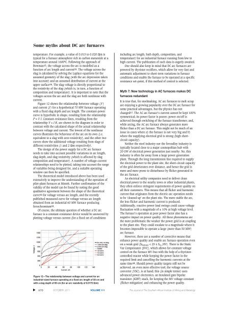
<strong>Some</strong> <strong>myths</strong> <strong>about</strong> <strong>DC</strong> <strong>arc</strong> <strong>furnaces</strong>temperature. For example, a value of 0.015 to 0.020 Ωcm istypical for a furnace atmosphere rich in carbon monoxide at atemperature around 1600ºC. Following the approach ofBowman13, the voltage across the <strong>arc</strong> is modelled as afunction of <strong>arc</strong> length and current15. The voltage across theslag is calculated by solving the Laplace equations for theassumed geometry of the slag (with the <strong>arc</strong> depression takeninto account) and an assumed distribution of current at theupper surface16. The slag voltage is directly proportional tothe resistivity of the slag (which is, in turn, a function ofcomposition and temperature). It is important to note that thevoltages across the <strong>arc</strong> and the slag are both nonlinear withcurrent.Figure 12 shows the relationship between voltage (V )and current (I ) for a hypothetical 70 MW furnace operatingwith a fixed slag depth and <strong>arc</strong> length. The constant-powercurve is hyperbolic in shape, resulting from the relationshipP = V I. Constant-resistance lines, resulting from therelationship V = I R, are shown in the diagram in order tocontrast with the calculated shape of the actual relationshipbetween voltage and current. The lowest of the nonline<strong>arc</strong>urves illustrates the behaviour of the <strong>arc</strong> on its own (i.e.equivalent to a slag with zero resistivity), and the other twocurves show the additional voltage resulting from slags ofdifferent resistivities (1 and 2 Ωcm respectively).The design of the power supply for a <strong>DC</strong> <strong>arc</strong> furnaceneeds to take into account possible variations in <strong>arc</strong> length,slag depth, and slag resistivity (which is affected by slagcomposition and temperature). A number of voltage–currentrelationships need to be plotted, taking into account the rangeof variables being designed for, and a suitable operatingwindow can then be specified.The theoretical model introduced above has been usedextensively to improve the understanding of the operation ofpilot-plant <strong>furnaces</strong> at <strong>Mintek</strong>. Further confirmation of thevalidity of the model can be found by noting the goodqualitative agreement between the shape of the theoreticalcurve16 for voltage versus <strong>arc</strong> length, and the recentlypublished measured curve for voltage versus <strong>arc</strong> lengthobtained from an industrial 60 MW furnace producingferrochromium10.Of course, the ultimate question of whether a <strong>DC</strong> <strong>arc</strong>furnace is a constant-resistance device would be answered byplotting voltage versus current (for a fixed set of conditionsFigure 12—The relationship between voltage and current for anindustrial-sized furnace operating at a fixed <strong>arc</strong> length of 50 cm andwith a slag depth of 60 cm (for an <strong>arc</strong> resistivity of 0.0175 Ωcm)including <strong>arc</strong> length, bath depth, composition, andtemperature) for an industrial furnace running from low tohigh current. The publication of such data is eagerly awaited.One should also keep in mind that <strong>DC</strong> <strong>arc</strong> <strong>furnaces</strong> arepowered by thyristor rectifiers, which allow for very fast andautomatic adjustment to short-term variations in furnaceconditions and enable the furnace to be operated at a specificresistance set-point, if this method of control is selected.Myth 7: New technology in AC <strong>furnaces</strong> makes <strong>DC</strong><strong>furnaces</strong> redundantIt is true that, for steelmaking, AC <strong>arc</strong> <strong>furnaces</strong> to melt scrapare enjoying a growing popularity over the <strong>DC</strong> <strong>arc</strong> furnace forsome practical advantages, but the physics has notchanged17. The AC <strong>arc</strong> furnace’s current cannot be kept 100%symmetrical; its power factor is poorer; power on/off isachieved through switching of the furnace transformer; and,while <strong>arc</strong>ing, the AC <strong>arc</strong> furnace always generates moreflicker than a <strong>DC</strong> <strong>arc</strong> furnace. This might not be much of anissue in cases where a) the furnace is not very big and b)where the supplying electrical grid is strong (high shortcircuitcapacity).Neither the steel industry nor the ferroalloy industry istypically located close to a major cosmopolitan hub with20 GW of electrical power generation just nearby. No, thisindustry is often far away from a large power generationplant. Through the long transmission line required to supplythe electrical power to the plant site, the short-circuit capacityof the grid deteriorates over distance, and hence the grid ismore and more prone to disturbance by flicker generated inthe <strong>arc</strong> furnace.As electrical utility companies need to deliver cleanelectrical power to the nearby town or other industrial plants,they often enforce stringent requirements of power quality onall their customers. This means that all flicker and harmoniccurrent that originates from the electric-<strong>arc</strong> operation needsto be ‘cleaned up’ on the plant site. The more stable the <strong>arc</strong>,the less flicker and harmonic current is produced.Additionally, reactive power load swings could cause voltagefluctuation with a magnitude of ± 10% at high voltage level.The furnace’s operation at poor power factor also has anegative impact on power quality. All these phenomena arethe more problematic the weaker the power grid is at couplingto the plant site. They could escalate to a magnitude where itbecomes impossible to operate a large (more than 50 MW)<strong>arc</strong> furnace.However, there are a number of corrective means thatenhance power quality and enable <strong>arc</strong> furnace operation evenon a weak grid (S furnace < 25 x S cc _HV). There is the StaticVar Compensator (SVC), which allows for constant voltagecontrol on the furnace MV-bus with the help of a thyristorcontrolledreactor while keeping the power factor in therequired limit and cancelling the harmonic currents at thesame time18. Should power quality targets still not beachieved, an even more effective tool, the voltage sourceconverter (VSC), is at hand; this (in simple terms) usesadvanced power electronics, an Insulated gate bipolartransistor (IGBT) stack, for keeping the MV voltage constant(flicker mitigation) and enhancing the power quality.▲670 OCTOBER 2011 VOLUME 111 The Journal of The Southern African Institute of Mining and Metallurgy