Furnace refractory erosion - Mintek
Furnace refractory erosion - Mintek
Furnace refractory erosion - Mintek

Create successful ePaper yourself
Turn your PDF publications into a flip-book with our unique Google optimized e-Paper software.
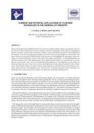
Paper presented at 58th Electric <strong>Furnace</strong> Conference, Orlando, Florida, November 13th, 2000.In 58th Electric <strong>Furnace</strong> Conference Proceedings: 361–78. Warrendale, PA.: Iron & Steel Society. 2000.An Anatomy of <strong>Furnace</strong> Refractory Erosion:Evidence from a Pilot-Scale FacilityPaul den HoedMINTEKPrivate Bag X30152125 RandburgSouth AfricaTelephone +27-11-709-4735Telefax +27-11-709-4564denhoed@mintek.co.zaKeywords: DC-arc, furnace, reverberatory, blast, copper, lead, slag, nickel laterite, chrome, magnesia,alumina, spinel, silicon carbide, graphite, <strong>refractory</strong>, corrosion, <strong>erosion</strong>, phase chemistryINTRODUCTIONPlasma-arc technology—and DC transferred-arc technology, in particular—has its adherents. 1, 2 MINTEK is oneof them. Since the late 1970s, it has sought to apply this technology to the recovery of valuable metals fromcertain ores and from furnace slags and dusts. Commercial furnaces are now in place for the production offerrochromium from chromite and for the smelting of ilmenite. Beginning with small-scale DC-arc furnaces, ithas demonstrated the application in four other areas: 2–7• The recovery of copper, nickel and cobalt from converter slags• The recovery of nickel from nickel laterite• The fuming of lead and zinc from lead blast-furnace slag (LBFS)• The removal of zinc and lead from electric-arc furnace (EAF) dusts collected during steelmakingThen, several years ago, the scale of work leapt with the commissioning of a 5.6 MVA (1–3 MW) facility. Thefurnaces, although larger (about 2.5 m in diameter), follow earlier designs—a cylindrical shell of water-cooledpanels; a conical roof, through which the graphite cathode passes; and the facility to feed charge close to thearc. In most applications, an alumina castable protects the roof and an MgO rammable the hearth. Therefractories of the sidewall, being the focus in this matter, vary according to the demands and concerns of eachcampaign. The right choice of <strong>refractory</strong> has always been integral to the success of a campaign. These days,the assessment of their performance provides invaluable pointers in choosing refractories for large-scale,industrial furnaces—it is for the purpose of designing these furnaces, after all, that campaigns on a pilot scaleare conducted.The campaigns themselves have been good vehicles for testing refractories under particular conditions.One can cite two reasons:1. Conditions in the small, pilot-scale furnace are sometimes more severe than those likely to be encounteredin a industrial-scale furnace. The dimensions are such that, more than once, high temperatures have2000 ELECTRIC FURNACE CONFERENCE PROCEEDINGS 361
prevented a freeze-lining from forming; and in at least one configuration, flaring from the arc impinged ona section of sidewall in the freeboard.2. Severity notwithstanding, of all the tests one can devise, a campaign in a pilot-scale furnace best simulatesthe conditions that will prevail in an industrial furnace. Heat transfer profiles are similar, and bothcorrosive and erosive forces are at play:• The hot-face is at the <strong>refractory</strong>-slag interface and temperature drops across the <strong>refractory</strong>. This standsin contrast to the cup test, in which a crucible of the <strong>refractory</strong>, or a cavity drilled into a brick of thematerial, is filled with slag and heated in a furnace. This configuration forces temperature, whenconditions have stabilized, to be uniform throughout the slag and <strong>refractory</strong>.• Continuous feeding and tapping keep the composition of slag in the bath constant. This maintains thechemical potentials driving corrosion. In the cup test, by contrast, the ratio of slag to <strong>refractory</strong> is low,with the effect that chemical potentials equalize when slag reacts with the <strong>refractory</strong>. The spindle test,in which a rotating rod of <strong>refractory</strong> is immersed in a bath of molten slag, would circumvent this flawof the cup test if the bath were large in comparison with the immersed <strong>refractory</strong>.• Turbulence in the slag bath creates an erosive environment, one that a <strong>refractory</strong> must withstand.These advantages, however, cannot offset the fact that tests in a pilot-scale furnace fail to give full and precisecontrol over conditions at the slag-<strong>refractory</strong> interface. In a post-mortem examination, one is consequentlyunable to distinguish between, let alone measure, the interactive processes between slag and <strong>refractory</strong>—thevery processes researchers consider to constitute corrosion and <strong>erosion</strong>. (This is a concern being addressed by agroup at CSIRO Minerals, Australia. It has developed a gravimetric technique for providing “directinformation” on the dynamic processes of wetting, penetration, dissolution and <strong>erosion</strong> of refractories by moltenslags. 8 ) We can, nonetheless, rank the performances of different refractories from similar campaigns; and,drawing on phase-chemical theory, we can interpret the clues offered by post-mortem examinations to identifythe causes of <strong>erosion</strong> in a particular <strong>refractory</strong>. The details may not all be there, but an account of the broadermechanisms is.A number of different refractories were used in several recent campaigns run in the 5.6 MVA, DC-arcfurnace at MINTEK. This paper describes aspects of their corrosion and <strong>erosion</strong>. It offers explanations for whathappened to them, and it draws some lessons regarding the choice of refractories in certain applications.MATERIALS AND CONDITIONSThe campaigns involved the smelting of siliceous materials at conditions designed to minimize the reduction ofiron from the slag in order to concentrate certain valuable metals. These metals can be recovered from anynumber of sources; this paper considers three:• Nickel laterites• Lead blast-furnace slags (LBFS)• Copper reverberatory-furnace slags (CRFS)The smelting of these materials produced slags of different composition (Table I). Comparing just these slags,one might highlight their relative qualities:• A slag rich in magnesia and silica• A slag rich in calcia and iron oxide• A slag rich in calcia and silica. The alkali levels in this slag were also unusually highThe refractories were both shaped and unshaped (tables II and III). 9 Except for the silicon carbide bricks,they were all of the oxide variety. Two of the refractories—one a magnesia brick, the other a spinel castable—contained graphite. (They were chosen for their high thermal conductivity; although graphite does inhibit slagpenetration, which increases resistance to spalling. 10 ) Only sub-sets of the refractories were used in eachcampaign (Table IV). Several of them—the magnesia, magnesia-chrome, spinel, and silicon carbiderefractories—were used in three or more campaigns.2000 ELECTRIC FURNACE CONFERENCE PROCEEDINGS 362
Table I. Average Compositions of Slags Tapped from the <strong>Furnace</strong> in 7 Campaigns(mass per cent)Ex Nickel Laterite Ex Lead Blast-<strong>Furnace</strong> Slag Ex Copper Reverberatory-<strong>Furnace</strong> Slag1 2 1 2 1 2 3CaO 0.3 0.3 20 23 20 19 13MgO 32 35 2.5 5 4 3.5 4FeO 16 13 39 36 17 17 20Al 2 O 3 2 5 5 4 9.5 9 9Cr 2 O 3 1.2 1.3 0.3 0.1 0.2 0.1 0.1SiO 2 47 45 25 22 46 46 49ZnO . . . . . . . . . . 4 4 . . . . . . . . . . . . . . .K 2 O + Na 2 O . . . . . . . . . . . . . . . . . . . . 4 4 4Principal Phases in the Cooled Slag(Mg,Fe) 2 SiO 4 (olivine) Ca 2 (Mg,Fe,Al)(Si,Al) 2 O 7 * Ca(Mg,Fe)(Si,Al) 2 O 6 (pyroxene I)(Mg,Fe)SiO 3 (pyroxene) (Fe,Mg)O (magnesiowüstite) CaFe 0.7 (Si,Al) 2.3 O 6 (pyroxene II)Ca(Fe,Mg)SiO 4 (kirschteinite)* Akermanite, which formed in slag 2 with cooling. It was the dominant phase.KAlSi 2 O 6 (leucite)Table II. Compositions of Shaped Refractories: Chemical †(mass per cent)MagnesiaMagnesia-CarbonMagnesia-ChromeFusedSpinelSiC-Si 3 N 4SiC-SiO 2MgO 96 87 59 28 . . . . . . . . . .Al 2 O 3 0.3 9 7.5 72 0.3 0.7Cr 2 O 3 . . . . . . . . . . 20 . . . . . . . . . . . . . . .Fe 2 O 3 0.3 0.5 10 0.1 0.3 0.7SiO 2 0.8 2.3 1.6 0.1 0.5 8.5Principal Phases (Approximate)MgO (periclase) 96 74 48 . . . . . . . . . . . . . . .Mg(Cr,Fe,Al) 2 O 4 (chromite) . . . . . . . . . . 49 . . . . . . . . . . . . . . .MgAl 2 O 4 (spinel) . . . . . 11 . . . . . 97 . . . . . . . . . .SiC . . . . . . . . . . . . . . . . . . . . 75 90Si 3 N 4 . . . . . . . . . . . . . . . . . . . . 23 . . . . .SiO 2 (cristobalite) . . . . . . . . . . . . . . . . . . . . . . . . . 9C (graphite) . . . . . 15 . . . . . . . . . . . . . . . . . . . .Physical Properties †Bulk Density (g.cm –3 ) 2.87 2.80 3.23 2.94 2.65 2.55Apparent Porosity (%) 18 10 16 17 17 18Thermal Cond. (W.m –1 .K –1 )* 4.1 (1000°C) 4.1 (1000°C) 2.6 (1000°C) 3.0 (1200°C) 16.3 (1480°C) 15.7 (1480°C)† From the manufacturers’ data sheets.* Thermal conductivity of the <strong>refractory</strong> at the temperature reported in brackets.Along with compositional differences in their slags, the campaigns differed in other respects. They didnot all run for the same duration. Nine days was the norm, but two of the campaigns ran for much longer2000 ELECTRIC FURNACE CONFERENCE PROCEEDINGS 363
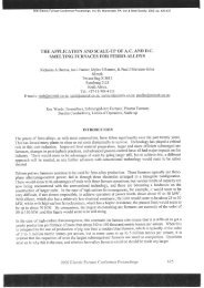
periods (Table IV). Temperatures were also different (Figure 1). On the assumption that the temperature oftapped slag reflects the temperature within the furnace, we can see that the second campaign in the smelting oflead blast-furnace slag maintained relatively low temperatures (~1400°C); the second campaign in the smeltingof nickel laterite, the hottest temperatures (~1700°C). The difference relates to the higher liquidus of the MgO-11, 12FeO-SiO 2 slag from nickel laterites compared with that of the CaO-FeO-SiO 2 slag from LBFS.Table III. Compositions of Unshaped Refractories: Chemical(mass per cent)Magnesia-ChromeAlumina-Chrome Alumina SpinelSpinel-CarbonCaO 3 0.2 1.5 1.8 1.6MgO 49 0.3 5 22 20Al 2 O 3 14 84 93 76 76Cr 2 O 3 18 10 . . . . . . . . . . . . . . .Fe 2 O 3 9 0.5 — 0.2 0.1SiO 2 6 4 0.1 0.2 0.1Principal Phases (Approximate)MgO (periclase) 30 . . . . . . . . . . . . . . . . . . . .(Mg,Fe)(Cr,Fe,Al) 2 O 4 (chromite) 55 . . . . . . . . . . . . . . . . . . . .MgAl 2 O 4 (spinel) . . . . . . . . . . 18 87 85Al 2 O 3 (corundum) . . . . . ü 75 10 10(Al,Cr) 2 O 3 (sesquioxide) . . . . . ü . . . . . . . . . . . . . . .CaMgSiO 4 (monticellite) 9 . . . . . . . . . . . . . . . . . . . .Mg 2 SiO 4 (olivine) 6 . . . . . . . . . . . . . . . . . . . .CA x (calcium aluminates) . . . . . . . . . . ü ü üC (graphite) . . . . . . . . . . . . . . . . . . . . 2.5Physical PropertiesBulk Density (g.cm –3 ) 3.0 3.1 2.9 2.8 2.8Past successes with certain refractories and a willingness to try new ones played a part in the choices ofrefractories made for the different campaigns. Physical factors were also considered. Any choice, however,should not fail to take cognizance of an important phase-chemical principle, that of the compatibility betweenslag and <strong>refractory</strong>. With thought given to it, the following precautions could be sounded:• The slags, which are rich in FeO, will tend to oxidize a silicon carbide <strong>refractory</strong> and accelerate its <strong>erosion</strong>.Only a freeze lining will prevent this reaction. The choice of silicon carbide in three of the campaigns(Table IV) was prompted by a need for high thermal conductivities in order to establish a freeze lining.• The slags will tend to oxidize the graphite in carbon-composite refractories, which will affect the wetting ofthe <strong>refractory</strong> and, therefore, slag penetration. Only a freeze lining will prevent this from happening.• The slags, which contain little Al 2 O 3 , will tend to dissolve alumina refractories. Avoid these refractoriesunless a freeze lining is guaranteed.• LBFS, which has relatively little silica, will dissolve silicate phases in those refractories that contain them.Choose refractories with little or no SiO 2 .The same phase-chemical principle, on the other hand, enables one to recommend that magnesia refractories beused in the smelting of nickel laterite, because the slag is rich in MgO.2000 ELECTRIC FURNACE CONFERENCE PROCEEDINGS 364
1.81.5a2Frequency1.20.90.60.310.01250 1350 1450 1550 1650 1750Temperature (°C)1.81.5b2Frequency1.20.90.610.30.01250 1350 1450 1550 1650 1750Temperature (°C)1.81.5cFrequency1.20.90.6230.310.01250 1350 1450 1550 1650 1750Temperature (°C)Figure 1. Temperatures of Tapped Slags(normalized variations in temperature).a. Smelting of nickel laterite.b. Smelting of lead blast-furnace slag.c. Smelting of Cu reverberatory-furnace slag.The numbers refer to campaigns (see Table I).2000 ELECTRIC FURNACE CONFERENCE PROCEEDINGS 365
Table IV. Combinations of Slags and Refractories: Shaped RefractoriesEx Nickel Laterite Ex Lead Blast-<strong>Furnace</strong> Slag Ex Copper Reverberatory-<strong>Furnace</strong> Slag1 2 1 2 1 2 3Magnesia ü . . . . . . . . . . . . . . . . ü üMagnesia-carbon . . . . . . . . . . . . . . . . ü . . . . . . . .Magnesia-chrome ü ü ü ü . . . . ü . . . .Spinel . . . . . . . . . . . . ü ü ü üSiC Nitride bonded . . . . . . . . . . . . ü . . . . ü üSiC Silicate bonded . . . . . . . . . . . . ü . . . . ü üUnshaped RefractoriesMagnesia-chrome . . . . ü . . . . . . . . . . . . . . . . . . . .Alumina-chrome . . . . . . . . ü . . . . . . . . . . . . . . . .Alumina . . . . . . . . . . . . . . . . ü . . . . . . . .Spinel . . . . . . . . . . . . . . . . ü . . . . . . . .Spinel-carbon . . . . . . . . . . . . . . . . ü . . . . . . . .Campaign Duration (days) 9 10 9 18 9 25 9REACTIONS, RESISTANCE AND FAILURESIn all seven campaigns, corrosion was the cause of failure in many of the refractories lining the sidewall of thefurnace. It manifested itself in two ways:1. As a dissolution reaction at the hot-face. The driving force in this process is the lower activity of the<strong>refractory</strong>-oxide component—i.e., MgO, Al 2 O 3 or Cr 2 O 3 —in the slag. (A similar imbalance drives FeOinto the <strong>refractory</strong>.) In a closed system, the dissolution process would continue until the slag reachedsaturation. In practice, however, because the slag composition is held constant, the point of saturation isnever reached and dissolution continues until the entire <strong>refractory</strong> is consumed.2. As a loss of refractoriness behind the hot-face. Here, slag penetrates the <strong>refractory</strong>. The introduction ofCaO, FeO and SiO 2 lowers the solidus temperature of the <strong>refractory</strong> to well below the prevailingtemperature. The consequence is a turning of part of the <strong>refractory</strong> to liquid. This weakens the <strong>refractory</strong>,making it susceptible to any turbulence in the slag or metal bath. As these currents impinge on the lining,so the <strong>refractory</strong> succumbs to <strong>erosion</strong>.Several local factors would determine which of these mechanisms prevailed at any point in the furnace or in any<strong>refractory</strong>. Structural characteristics (i.e., the porosity and grain-size distribution of a <strong>refractory</strong>) and interfacialproperties (i.e., the surface tension between a given slag and <strong>refractory</strong>, which influences wetting) determine theextent to which a slag will penetrate a <strong>refractory</strong>. On the other hand, high temperatures in the furnace and sharpgradients in the <strong>refractory</strong> lining would tend to favour reactions at the hot-face over those behind it. Withoutour having measured the physical properties directly, we can only infer their likely effects from a post-mortemexamination of the refractories in the light of generally understood principles, or remain silent.MgAl 2 O 4 (Spinel) in Contact with CRFSWe can represent this combination by compositions within the system CaO-MgO-Al 2 O 3 -SiO 2 . (The systemaccounts for the principal species in the slag at and behind the hot-face. We can ignore FeO on the grounds thatFe 2+ will diffuse into the grains of spinel, which accommodates it in solid solution. This, indeed, is whathappened.) Phase relations at liquidus temperatures in the system have been published for planes of constant11, 12Al 2 O 3 . The composition of CRFS can be represented on the diagram cutting the 10% Al 2 O 3 plane of thesystem (10% approximates the alumina content of the slag—Table I). It lies over the pyroxene primary-phasefield. At 1550–1600°C, therefore, the slag is not in equilibrium with MgAl 2 O 4 (spinel); being unsaturated with2000 ELECTRIC FURNACE CONFERENCE PROCEEDINGS 366
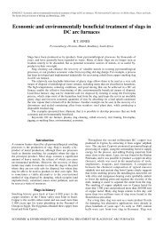
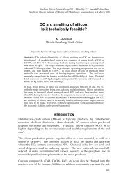
MgO and Al 2 O 3 , it will dissolve the <strong>refractory</strong> until it is in equilibrium with MgAl 2 O 4 . The dissolution processcan be tracked through the system across planes of increasing Al 2 O 3 : at 15% Al 2 O 3 , the spinel primary-phasefield has appeared and begun expanding; at 25% Al 2 O 3 , the slag composition has begun to move over the spinelfield; between 30 and 35% Al 2 O 3 , it moves across the 1550–1600°C isotherms. Only when the pointrepresenting the slag composition falls within the spinel primary-phase field and converges with the isothermrepresenting the bath temperature does further dissolution of spinel from the <strong>refractory</strong> cease. The point ofsaturation is reached when the Al 2 O 3 fraction in the slag has risen to between 30 and 35%; in the process, theslag will have consumed 45–65% of its mass in MgAl 2 O 4 (spinel). Without a freeze lining, therefore, one canexpect CRFS to do considerable damage to spinel refractories.That the bricks of fused spinel sustained severe <strong>erosion</strong> is a clear indication that a freeze lining was notmaintained at the base of the furnace (Figure 2a). Further up the sidewall, cooling panels held downtemperatures in the lining sufficiently for corrosion and <strong>erosion</strong> to have been minimal (Figure 2b). Themicroscopic evidence points to a dissolution of MgAl 2 O 4 (spinel) at the hot-face as the mechanism of <strong>erosion</strong>:• As Figure 3 strikingly shows, the slag-<strong>refractory</strong> interface ‘slices through’ MgAl 2 O 4 (spinel) grains at theeroded face of the fused-spinel brick; the interface is sharp and smooth over the full surface of the hot-face.No loose grains of spinel lay in the layer of slag adhering to the hot-face, a sign that the <strong>refractory</strong> had notfirst been weakened by corrosion and then washed by currents into the bath.• Slag penetrates the matrix in both brick and castable. Within the pores, its composition is enriched inAl 2 O 3 . Analyses of the slag phase trace a sharp increase in the level of Al 2 O 3 from a point at the hot-face(~10%) to one just behind it (>25%). There was no evidence that the reaction of slag with MgAl 2 O 4(spinel) in the pores of the <strong>refractory</strong> contributed to <strong>erosion</strong>.a0 10 cmb0 10 cmFigure 2. Corrosion/Erosion of SpinelRefractories in Contact with CRFS.a. Brick of fused spinel from base of furnace.b. Castable against cooling panel.2000 ELECTRIC FURNACE CONFERENCE PROCEEDINGS 367
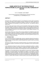
slaghotfaceMgAl 2O 40 300 µmFigure 3. Refractory-Slag Interactions at theHotface of a Spinel Brick.Micrograph of the backscattered-electron image.Magnesia-Chrome in Contact with LBFSIn theory, one can represent this combination by compositions in the system CaO-MgO-FeO-Cr 2 O 3 -SiO 2 . Inpractice, however, given the constraints of presenting phase diagrams in two dimensions and omissions in thecorpus of published diagrams, such a representation is no easy task. The composition of the slag maps11, 12conveniently onto the phase diagram for the system CaO-iron oxide-SiO 2 in contact with metallic iron.Introducing MgO (periclase) and Mg(Cr,Fe,Al) 2 O 4 (chromite)—phases making up the <strong>refractory</strong>—complicatesmatters immeasurably. A simpler tack is desirable. The marked difference in compositions of the slag and<strong>refractory</strong> suggests that the two might be incompatible. Whereas the <strong>refractory</strong> contains about 60% MgO(Table II), the slag contains no more than 5% MgO (Table I). The considerable disparity in these numbersmake it very likely indeed that LBFS, in contact with a magnesia-chrome <strong>refractory</strong>, is unsaturated with MgO.(Despite similar differences in Cr 2 O 3 , the chrome solubility in such FeO-rich slag—by implication, fairlyoxidizing—would be low.) The evidence of microscopy and energy dispersive spectrometry (EDS) supportsthis conclusion:• The hot-face defines a sharp boundary between the <strong>refractory</strong> and the slag of the bath (Figure 4). Wewould interpret this feature as <strong>erosion</strong> by dissolution.• Not only is the cooled slag adjacent to the hot-face enriched in Mg 2+ , but, where it has been left relativelyundisturbed, a spinel rich in magnesia and chrome has crystallized from the molten slag. This phase and itschrome-magnesia-rich composition indicate that the slag in this area, shielded from turbulence in the slagbath, had reached saturation, the outcome of a dissolution process.Not surprisingly, without a freeze-lining to protect them, the magnesia-chrome bricks that contained the slagbath were severely eroded in the shorter campaign and entirely consumed within 18 days (Table IV). Erosionwas just as severe in magnesia-chrome refractories lining the lower sections of the freeboard.2000 ELECTRIC FURNACE CONFERENCE PROCEEDINGS 368
MgO(Mg,Fe 2+ )(Cr,Al,Fe 3+ ) 2O 4hotfaceslag0 1.5 mmFe 2O 3Figure 4. Refractory-Slag Interactions at theHotface of a Magnesia-Chrome Brick.Micrograph of the backscattered-electron image.Magnesia, Mag-Chrome and Ni Laterite SlagsConsidering the high level of MgO in the slag (Table I), one would be prudent in lining the furnace with amagnesia <strong>refractory</strong>. The evidence seems to bear out the validity of this line of reasoning. Not that <strong>erosion</strong> didnot occur; rather, bricks of magnesia in the samples we collected sustained less <strong>erosion</strong> over the hot-face incontact with the slag bath than those of magnesia-chrome (cf. figures 5 and 6. The localized <strong>erosion</strong> coincidentwith the metal-slag interface—grooves marked X—is a manifestation of the Marangoni effect 13, 14 ). We canexplain the difference with reference to the appropriate phase diagrams. The combination of a magnesia<strong>refractory</strong> in contact with a slag produced in the smelting of nickel laterite can be represented by the systemMgO-SiO 2 . As in a previously discussed combination, we can ignore FeO on the grounds that Fe 2+ diffusesinto MgO (periclase), which accommodates it in solid solution. We found phases of the slag in close proximityto grains of MgO to contain far less FeO than the bulk slag; the grains themselves had become (Mg,Fe)O(magnesiowüstite). Looking at the phase diagram for the system MgO-SiO 2 , one can see that pointsrepresenting the slag—compositions between 55 and 60% SiO 2 at temperatures between 1600 and 1700°C—lie11, 12within the liquid field close to the Mg 2 SiO 4 (olivine) liquidus. As Mg 2 SiO 4 (olivine) co-exists with MgO(periclase) at these temperatures, we can conclude that the slag is just short of being saturated with MgO. Thedriving force in dissolution—corresponding to the displacement between the compositions of the slag andliquidus on the phase diagram—would be relatively small.For a magnesia-chrome <strong>refractory</strong>, by contrast, this driving force is much greater. Here, though, theexercise is complicated by more components in the system to be considered. There is as yet no complete phasediagram for system MgO-FeO-Cr 2 O 3 -Al 2 O 3 -SiO 2 in equilibrium with metallic iron. The phase diagrams tofour sub-systems, however, give some indication of what one can expect to find in the larger system. The four11, 12are—• MgO-Cr 2 O 3 -SiO 2 in equilibrium with air• MgO-Cr 2 O 3 -SiO 2 in equilibrium with metallic chromium• MgO-Al 2 O 3 -SiO 2• FeO-Al 2 O 3 -SiO 2 in equilibrium with metallic iron2000 ELECTRIC FURNACE CONFERENCE PROCEEDINGS 369
metal bathslag bathX0 10 cmFigure 5. Erosion of a Magnesia Brick in theSmelting of Nickel Laterite.X marks the eroded groove formed at the slagmetalinterface.metal bathslag bathX0 10 cmFigure 6. Erosion of a Magnesia-Chrome Brickin the Smelting of Nickel Laterite.X marks the eroded groove formed at the slagmetalinterface.At 1700°C, the liquid field covers a very small area of the system MgO-Cr 2 O 3 -SiO 2 in equilibrium with air. Itexpands across the phase diagram when the system is in equilibrium with metallic chromium. 12 Becausemetallic iron imposes a less reducing potential than does metallic chromium, we can expect the liquid field tocover an area of intermediate extent when the system MgO-Cr 2 O 3 -SiO 2 is in equilibrium with metallic iron.Phase relations in the second and third phase diagrams would suggest that, with the introduction of Al 2 O 3 andFeO into the system, the liquid field expands in other directions. The slag composition falls within this field; italso lies within the confines of the olivine primary-phase field, possibly close to the olivine liquidus. The slagcomposition is at some remove from the spinel liquidus, however. One can follow the implication of thisgeometry with the introduction of a magnesia-chrome <strong>refractory</strong> into the picture. The <strong>refractory</strong> is a compositeof MgO (periclase) and Mg(Cr,Fe,Al) 2 O 4 (chromite; see Table II). In contact with MgO (periclase), the slagshould be slightly unsaturated with MgO; in contact with Mg(Cr,Fe,Al) 2 O 4 (chromite), it should be unsaturatedwith Cr 2 O 3 and Al 2 O 3 by a considerable margin. Cr 2 O 3 and Al 2 O 3 will dissolve into the slag. This wouldexplain the <strong>erosion</strong> of magnesia-chrome refractories during the campaign.Quite how active the dissolution process is, is suggested by the sharp divide between slag and <strong>refractory</strong>at the hot-face (Figure 7). The presence of pores immediately behind the hot-face suggests that the penetration2000 ELECTRIC FURNACE CONFERENCE PROCEEDINGS 370
of slag into the <strong>refractory</strong> is minimal, if not marginal. The mechanism of <strong>erosion</strong>, therefore, was by thedissolution of <strong>refractory</strong> at the hot-face, and not by any corrosion and disintegration of the <strong>refractory</strong> behind it(although this does seem to have been the mechanism of <strong>erosion</strong> at the slag-metal interface).0 600 µmglass• ol 1sp 1•slag<strong>refractory</strong>mw 1• • ol2mw 2•• sp 2poreFigure 7. A Chromite Aggregate at the Hot-Faceof a Magnesia-Chrome Brick (NickelLaterite Smelting).Micrograph of the backscattered-electron image.LEGENDol 1 Mg 1.9 Fe 0.1 Si 1.0 O 4ol 2 Mg 1.9 Fe 0.1 Si 1.0 O 4sp 1 Mg 0.9 Fe 0.1 (Cr 1.1 Al 0.9 )O 4mw 1 Mg 0.86 Fe 0.10 Cr 0.02 Osp 2 Mg 0.9 Fe 0.1 (Cr 1.0 Al 0.9 Fe 0.1 )O 4mw 2 Mg 0.87 Fe 0.09 Cr 0.02 OWhile the magnesia-chrome brick displayed a consistent pattern of <strong>erosion</strong>, slag-<strong>refractory</strong> interactions inthe magnesia-chrome castable varied. This variation reveals something of the effect that different conditionshad on the <strong>erosion</strong> process, because, unlike the bricks, the castable spanned much of the height of the sidewall,and local conditions varied up the wall. We identified three contexts:• Against the cooling panel in contact with the slag pool. Slag had penetrated the <strong>refractory</strong> and brought onthe disintegration of the hot-face, which consequently lacked definition.• Against the cooling panel in the freeboard. There is some penetration of slag into the <strong>refractory</strong>, but the<strong>refractory</strong> retains a sharp edge with the slag.• Above the cooling panel in the freeboard. The slag adhering to the hot-face is layered, and the hot-face,following its disintegration by slag, lacks definition.In all three instances, slag had penetrated the <strong>refractory</strong>. We would surmise that the porosity of the castable andthe Ca, Mg silicates in its matrix facilitated this penetration. But, given that all internal factors would have beenequal in each instance, the process of <strong>erosion</strong> had to have been controlled by one or more external factors. Weknow that at least one condition varied up the sidewall, namely, the thermal history of the hot-face at eachlocation. The factors at play here are the impositions of temperature from the bath or the freeboard and theforced cooling imposed on the <strong>refractory</strong> by the cooling panel. The likely combination of their effects seems tobe consistent with our observations. The second context combined the forced cooling of the panel with thecooler, more stable environment of the freeboard. Along with forcing down the temperature of the hot-face, the2000 ELECTRIC FURNACE CONFERENCE PROCEEDINGS 371
combination would have imposed a steadier temperature on the hot-face. The effect would have minimizedslag penetration and the attendant disintegration of <strong>refractory</strong> behind the hot-face; the hot-face itself would havereceded (through dissolution) until its temperature matched the liquidus of the slag. In the first and thirdcontexts, the hot-face of the castable would either have been subjected to greater fluctuations in temperatures, ornot have had the benefit of forced cooling. The slag in the pores would have set up a zone of disintegration thatmarks the hot-face as indistinct.Alumina, Alumina-Chrome and LBFS or CRFSThe two combinations are an alumina castable in contact with CRFS and an alumina-chrome rammable incontact with LBFS (tables II and III). The castable contained over 98% Al 2 O 3 + MgO; the rammable,~4% SiO 2 . Both refractories lined the sidewall against the slag bath and the freeboard, and both shieldedcooling panels.The project investigators installed these refractories with different purposes in mind. Their intention wasfor nothing of the alumina-chrome rammable to remain, which is what happened, save for small fragmentsisolated in a corner of the lining. The alumina <strong>refractory</strong> was meant to survive, which it did: ~3 cm of the liningremained against the panels. Sections through samples of the alumina castable revealed the slag to havepenetrated ~1 cm of the <strong>refractory</strong>. On the other hand, a section through the alumina-chrome fragment revealedlittle penetration—indeed, the slag encountered the <strong>refractory</strong> at a fairly sharp interface; the hot-face was welldefinedacross matrix and aggregates.How do these results square with phase-chemical theory? Both refractories, being essentially alumina,would have been incompatible with either slag, which contain less than 10% Al 2 O 3 . The unsaturated slagwould have dissolved Al 2 O 3 from the refractories. The alumina-chrome <strong>refractory</strong> would have been furtherdisadvantaged by Cr 2 O 3 and SiO 2 . That the alumina castable survived as it did, even that a fragment ofalumina-chrome <strong>refractory</strong> survived, attests to the efficacy of the cooling panels, if not the properties of therefractories. The fragment of alumina-chrome <strong>refractory</strong> was particularly revealing. Over much of thesidewall, its chemical composition, along with the control of energy flux through the wall, allowed slag to erodethe <strong>refractory</strong>; yet in the fragment, there was little penetration of the matrix by slag and no sign of anyweakening of <strong>refractory</strong> behind the hot-face. Erosion occurred by the dissolution of <strong>refractory</strong> at the hot-face.Because the fragment survived, we would surmise that the lining in that vicinity probably benefited from bettercooling and less turbulence.Silicon Carbide and LBFS or CRFSNitride-bonded silicon carbide (SiC-Si 3 N 4 ) lined the sidewall in contact with the slag bath of three campaigns.Investigators reasoned that the high thermal conductivity of the <strong>refractory</strong> (see Table II) would make it easier toestablish a freeze lining, and so preserve the <strong>refractory</strong>. The unexpected happened, however. Whereas thelining survived largely intact after 25 days of smelting CRFS at ~1550°C, it disappeared after 18 days ofsmelting LBFS at ~1400°C. Clearly, for a time at least, a freeze lining did not exist. It was only afterinvestigators pointed out measures taken to prepare the lining for the LBFS campaign that we could make senseof this result. We now believe the destruction of the SiC lining in that campaign to have been initiated during a36 hour period prior to commencement. Because the bricks did not fit tightly together, the gaps between themwere filled with a SiC mortar, which required curing. Burners were lit. They would have oxidized SiC to SiO 2 ,which would subsequently have dissolved readily in slag. The lining would have eroded fairly quickly.Had this not happened, however, the <strong>refractory</strong> would still have faced another destructive process—albeita far milder one. The evidence appeared in a sample from the CRFS campaign. Close examination of<strong>refractory</strong> near the hot-face identified three features not present in the virgin <strong>refractory</strong>:• Specs of carbon in the matrix of the <strong>refractory</strong>.• A layer of silica (SiO 2 ) on the surfaces of many particles of SiC (Figure 8). This would suggest thatconditions in the furnace were sufficiently oxidizing for SiO 2 to form from SiC.2000 ELECTRIC FURNACE CONFERENCE PROCEEDINGS 372
• An alloy phase containing high levels of silicon (Figure 9—an analysis of the alloy at one point recorded15% Si).SiCporeSiO 2 -3% CSi 3 O 0.2 N 3.10 100 µmFigure 8. Near the Hot-Face of SiC-Si 3 N 4Refractory: Formation of SiO 2 .Micrograph of the backscattered-electron image.To explain these features, we refer to the oxygen potentials of several buffers (Figure 10). Each of the shadeddiscs represents a set of desirable operating conditions for a campaign. Here, desirable refers to the minimalreduction of iron from the slag so that the liquid alloy will concentrate the valuable metals. The equilibriumcurves for these metals lie above the shaded discs, which in turn lie close to the Fe 0 -FeO buffer. Theseoperating conditions will oxidize SiC to SiO 2 : the reaction is driven by an oxygen potential of ~8 log pO 2 units,the difference in oxygen fugacities of the shaded discs and the SiC-SiO 2 buffer. Within the lining, the presenceof SiO 2 and SiC will establish a local oxygen fugacity according to the SiC-SiO 2 buffer curve. In practice, byvirtue of its proximity to the Si-SiO 2 buffer—less than 2 log pO 2 units separate the two buffer curves—this pO 2is sufficiently reducing for the formation of a dilute, Si-bearing alloy. Thus, conditions near the hot-face of aSiC <strong>refractory</strong> stabilize SiO 2 and silicon. SiO 2 , being soluble in slag, will facilitate the <strong>erosion</strong> of the lining.Silicon, on the other hand, should report to the liquid alloy. This, indeed, is what happened.2000 ELECTRIC FURNACE CONFERENCE PROCEEDINGS 373
Si 3 N 3.4Fine intergrowth ofphases that include—• Fe, Si, Co alloy• Cu, Fe sulfideSiC0 500 µmFigure 9. Near the Hot-Face of SiC-Si 3 N 4Refractory: Si-Enriched Metal.Micrograph of the backscattered-electron image.Graphite in RefractoriesOxygen fugacities in CRFS also played a role in the performances of the two refractories that contained carbon.The two were installed for their thermal conductivities, the spinel-carbon castable in the sidewall in contact withthe slag bath. After the campaign, it was found to be covered by a plate of metal; the plate took the unevenform of liquid iron running down the sidewall. The <strong>refractory</strong> behind the hot-face was marked by the absenceof graphite flakes; slag had penetrated the pores. There can be little doubt that graphite in the <strong>refractory</strong>reduced some of the considerable FeO in the slag. Liquid metal precipitated against the hot-face, while the lossof carbon opened up pores to the infiltration of slag. The formation of metal could have had a beneficialconsequence, however: as the metal formed against the hot-face, it could have shielded the <strong>refractory</strong> from thecorrosive effects of the slag bath. On the whole, the <strong>erosion</strong> of this <strong>refractory</strong> was not noticeably worse than itsnon-carbon counterpart.2000 ELECTRIC FURNACE CONFERENCE PROCEEDINGS 374
-5BA-10SiO 2SiC-15FeOFe 0log p O 2CO 2CO + C-20SiO 2Si metal-25-30900 1100 1300 1500 1700Temperature (°C)Figure 10. Oxygen Potential Diagram: RelativeStabilities of Different Buffers.(Constructed from thermochemical data. 15 ) Thetwo shaded discs mark desirable operatingconditions—A For the smelting of LBFS.B For the smelting of CRFS.At these conditions, the reduction of Fe 2+ tometallic iron should be minimal.The magnesia-carbon bricks were never meant to come into contact with either molten slag or liquidmetal; they were shielded by an inner course of refractories. But the latter suffered excessive <strong>erosion</strong>, whichexposed some surface of the magnesia-carbon bricks to the bath. Erosion was severe.Spinel Refractories in the FreeboardIn several of the campaigns, investigators favoured spinel refractories in the sidewall of the freeboard. Brickswere preferred to castables; only in one of the earlier campaigns did a furnace run with a castable lining. Itspalled severely. In casting about for an explanation, we ruled out stress caused by a possible volume change infiring. The change in <strong>refractory</strong> volume was negligible.Firing—or rather the lack of it—seemed have been the critical factor in spalling. The manufacturer of thespinel castable stipulated a programme of drying followed by firing. All that the castable in the furnace got wasa partial curing at 400°C (higher temperatures would have damaged the cooling panels behind the <strong>refractory</strong>lining). Laboratory tests on pressed pellets of the castable demonstrated that firing at 1400°C (as stipulated)gave the <strong>refractory</strong> a strength that was wholly lacking in the material cured at 400°C. The lining, therefore, wasinadequately prepared for the rigour of a smelting campaign.That said, however, a brick of fused-spinel from the freeboard of the second LBFS campaign showedspalling (Figure 11). Although slag temperatures in the bath were much cooler (cf. figures 1b and 1c), the2000 ELECTRIC FURNACE CONFERENCE PROCEEDINGS 375
electrode configuration raised the level of arc flaring in the freeboard. But if flaring were the sole cause, thenthe magnesia-chrome refractories in the freeboard should also have shown signs of spalling, which they did not.Spinel refractories, it seems, are particularly susceptible to spalling when attacked by slags, castables more sothan fused-spinel. Conditions such as arc flaring may exacerbate matters.0 10 cmFigure 11. Spalling at the Hotface of a Fused-Spinel Brick from the Freeboard.Cr-bearing Refractories and CRFSFor the second campaign in the smelting of CRFS, magnesia-chrome bricks were installed in the sidewall of thefurnace. Those lining the freeboard fared well. Samples were collected and sectioned for examination. Soonafter they were cut, however, a bright yellow salt began appearing on their surfaces (but not on the hot-face orthe compact zone immediately behind it). Powder X-ray diffractometry identified a mixture of K 3 NaCr 2 O 8 andK 2 CrO 4 (tarapacaite). Both are salts of chromium(VI). Their appearance followed the use of water duringcutting: it dissolved and mobilized the Cr(VI) salts, which then crystallized on the surface.The formation of Cr(VI) salts recalls the alkali roasting of chromite ores. In that process, chromite isroasted with sodium carbonate in air at 1100–1150°C to convert trivalent chromium to its hexavalent form. 16 Asimilar reaction took place in the magnesia-chrome refractories of the freeboard. The key agents werepotassium and sodium: the fumes from the bath contained almost 15% K 2 O (cf. Table I). These alkalis, alongwith enough oxygen in the freeboard of the furnace, would have initiated the following reaction:76+1FeCr 2 O2= 2K2CrO 4 + Fe 2O223+2 O4+ K 2O+{in chromite} {in vapour}It is significant that Cr(VI) salts formed only in the magnesia-chrome refractories of the freeboard; the sectionedmagnesia-chrome bricks from the slag-metal line were devoid of yellow crystals. Beneath the surface of theslag pool, conditions would have been too reducing for the formation of alkali chromates(VI).The threat Cr(VI) poses to health compelled investigators to ban chrome-based refractories from furthercampaigns to smelt CRFS. In the smelting of nickel laterites and LBFS, however, none of the chrome-bearingrefractories showed any discernable Cr(VI).CONCLUSIONS AND LESSONSThe 5.6 MVA, DC-arc furnace at MINTEK has proved itself an invaluable facility for testing refractories incontact with slags under the harshest of smelting conditions. Unlike the practice in industry, where furnaces run32000 ELECTRIC FURNACE CONFERENCE PROCEEDINGS 376
with a freeze lining, there were times when the pilot-scale tests described in this paper did not run with one. Wewere able, therefore, to see how well refractories survived in direct contact with molten slag over a number ofdays. Our examinations of the phases in and morphologies of reaction zones, interpreted in the light ofappropriate phase-chemical theory, provided a means for explaining what happened. Our observations lead usto conclude that—• The dissolution of <strong>refractory</strong> at the hot-face is the principal mechanism by which oxide refractoriessubmerged in a slag bath are eroded. This holds for the smelting of nickel laterite, lead blast-furnace slagand copper reverberatory-furnace slag. The mechanism appears to outweigh any loss of refractorinessbehind the hot-face. There are even indications that differences in structural or physical properties matterlittle.• Dissolution is driven by the low chemical potentials of one or more of the <strong>refractory</strong> oxides in the slags;being unsaturated with MgO, Al 2 O 3 , or Cr 2 O 3 , the slags dissolve these oxides from the refractories.• In fused-spinel bricks in contact with CRFS and magnesia-chrome bricks in contact with either LBFS orslag from nickel laterite, <strong>erosion</strong> is severe. Magnesia bricks appear to offer better resistance to slags fromthe smelting of nickel laterites—which are rich in MgO—than do magnesia-chrome bricks.• Even if a proper freeze lining is not established, cooling panels in the sidewall can be effective in haltingthe <strong>erosion</strong> of <strong>refractory</strong> linings.• Siliceous slags rich in FeO are potentially destructive towards SiC refractories. They oxidize SiC to SiO 2 ,which either dissolves in slag, thereby facilitating the <strong>erosion</strong> of the <strong>refractory</strong>, or establishes anequilibrium with silicon, which reports to the metal as a contaminant. The formation of SiO 2 may alsochange the thermal conductivity of the <strong>refractory</strong> enough to destabilize a freeze lining.• Slags rich in FeO are potentially destructive towards carbon/graphite in refractories. Carbon reduces FeOand certain other oxides to metal. Without graphite protecting them, these refractories are more susceptibleto the corrosive effects of slag.• Unshaped refractories must be properly cured. If this cannot be done, find an alternative.• Spinel refractories lining the freeboard tend to spall. Castables may do so more readily than bricks of fusedspinel.• CRFS produces Cr(VI) in chrome-bearing refractories lining the freeboard. Keep such refractories awayfrom any furnace smelting slags with even a few per cent K 2 O or Na 2 O.ACKNOWLEDGEMENTSI thank two colleagues, Johan Nell and Rodney Jones, for reading through and commenting on a draft of thispaper. I am indebted to my colleagues in the Pyrometallurgy Division for passing countless samples ofrefractories on to me for study; in particular, my thanks go to Glen Denton, Herman Lagendijk, Genine Assisand Mata Botima. I am grateful to MINTEK for its consent to the publication of this paper.REFERENCES1. R.T. Jones, T.R. Curr and N.A. Barcza, “Development of plasma furnace technology at <strong>Mintek</strong>,” Miner.Ind. Int., No. 1017, March 1994, pp. 25–31.2. R.T. Jones, D.A. Hayman and G.M. Denton, “Recovery of cobalt, nickel, and copper from slags, usingDC-arc furnace technology,” in C.A. Pickles, P.J. Hancock and J.R. Wynnyckyj (eds) Challenges inProcess Intensification, Proceedings of the International Symposium, Canadian Institute of Mining,Metallurgy and Petroleum, Montreal, 1996, pp. 451–66.2000 ELECTRIC FURNACE CONFERENCE PROCEEDINGS 377
3. A.F.S Schoukens, L.R. Nelson and N.A. Barcza, “Plasma-arc treatment of steel-plant dust and zinccontainingslag—Theoretical and practical considerations,” in Recycling Lead and Zinc: The Challengesof the 1990’s, International Lead and Zinc Study Group, London, 1991, pp. 361–70.4. A.F.S. Schoukens, F. Shaw and E.C. Chemaly, “The Enviroplas process for the treatment of steel-plantdusts,” J. S. Afr. Inst. Min. Metall., Vol. 93, No. 1, Jan. 1993, pp. 1–7.5. A.F.S. Schoukens, G.M. Denton and R.T. Jones, “Pilot-plant production of prime western grade zincfrom lead blast-furnace slags using the Enviroplas process,” in P.B. Queneau and R.D. Peterson (eds),Third International Symposium, Recycling of Metals and Engineered Materials, The Minerals, Metals &Materials Society, Warrendale, Penn., 1995, pp. 857–68.6. N.A. Barcza, D.G.C. Robertson, A.F.S. Schoukens, F. Shaw, G.M. Denton, T.W. Worcester and D.J.Bailey, “Enviroplas technology for the recovery of lead and zinc from lead blast furnace slags,” inRecycling Lead and Zinc into the 21st Century, International Lead and Zinc Study Group, London,1995, pp. 73–89.7. H. Lagendijk and R.T. Jones, “Production of ferronickel from nickel laterites in a DC-arc furnace,” inC. Díaz, I. Holubec and C.G. Tan (eds) Pyrometallurgical Operations, the Environment and VesselIntegrity in Nonferrous Smelting and Converting, Proceedings of the Nickel-Cobalt 97 InternationalSymposium—Volume III, Canadian Institute of Mining, Metallurgy and Petroleum, Montreal, 1997,pp. 151–62.8. S. Jahanshahi, D. Xie and T. Tran, “In-situ gravimetric studies of wetting, penetration and wear ofrefractories by molten slags,” in Sixth International Conference on Molten Slags, Fluxes and Salts,Department of Materials Science and Engineering, KTH, Sweden, 2000, 18 pp.9. M. Hayase, “Introduction to refractories: Definition and classification,” in C.E. Semler, J. Homeny, G.Hand, G. MacZura and M. Madono (eds) Refractories Handbook, The Technical Association ofRefractories, Japan, Tokyo, 1998, pp. 2–7.10. H. Tada, “Carbon containing refractories: Magnesia-carbon,” in C.E. Semler, J. Homeny, G. Hand, G.MacZura and M. Madono (eds) Refractories Handbook, The Technical Association of Refractories,Japan, Tokyo, 1998, pp. 170–82, 189–90.11. A. Muan and E.F. Osborn, Phase Equilibria Among Oxides in Steelmaking, Addison-Wesley PublishingCo., Reading, Mass., 1965.12. M. Kowalski, P.J. Spencer and D. Neuschütz, “Phase diagrams,” in D. Springorum/VDEh (eds) SlagAtlas, 2nd edition, Verlag Stahleisen, Düsseldorf, 1995, pp. 21–214.13. K. Mukai, “Wetting and Marangoni effect in iron and steelmaking processes,” ISIJ Int. Vol. 32, No. 1,1992, pp. 19–25.14. J.R. Donald, P.H. Lauzon, S.W. Ip and J. Duran, “Investigations into <strong>refractory</strong> wear at Cerro MatosoS.A.,” CIM Bull. Vol. 92, 1999, pp. 124–30.15. O. Knacke, O. Kubaschewski and K. Hesselmann (eds), Thermochemical Properties of InorganicSubstances, 2nd edition, Springer-Verlag, Berlin, 1991.16. B.J. Page and G.W. Loar, “Chromium compounds,” in J.I. Kroschwitz and M. Howe-Grant (eds) Kirk-Othmer Encyclopedia of Chemical Technology, Volume 6, John Wiley & Sons, New York, 1993,pp. 263–311.2000 ELECTRIC FURNACE CONFERENCE PROCEEDINGS 378