Some myths about DC arc furnaces - Mintek
Some myths about DC arc furnaces - Mintek
Some myths about DC arc furnaces - Mintek

You also want an ePaper? Increase the reach of your titles
YUMPU automatically turns print PDFs into web optimized ePapers that Google loves.
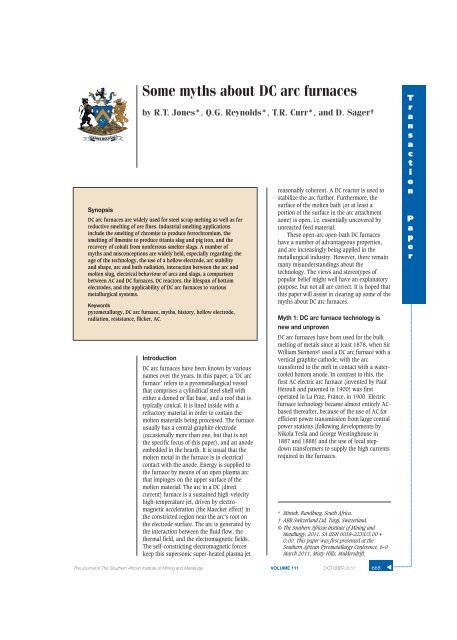
Synopsis<strong>Some</strong> <strong>myths</strong> <strong>about</strong> <strong>DC</strong> <strong>arc</strong> <strong>furnaces</strong>by R.T. Jones*, Q.G. Reynolds*, T.R. Curr*, and D. Sager†<strong>DC</strong> <strong>arc</strong> <strong>furnaces</strong> are widely used for steel scrap melting as well as forreductive smelting of ore fines. Industrial smelting applicationsinclude the smelting of chromite to produce ferrochromium, thesmelting of ilmenite to produce titania slag and pig iron, and therecovery of cobalt from nonferrous smelter slags. A number of<strong>myths</strong> and misconceptions are widely held, especially regarding: theage of the technology, the use of a hollow electrode, <strong>arc</strong> stabilityand shape, <strong>arc</strong> and bath radiation, interaction between the <strong>arc</strong> andmolten slag, electrical behaviour of <strong>arc</strong>s and slags, a comparisonbetween AC and <strong>DC</strong> <strong>furnaces</strong>, <strong>DC</strong> reactors, the lifespan of bottomelectrodes, and the applicability of <strong>DC</strong> <strong>arc</strong> <strong>furnaces</strong> to variousmetallurgical systems.Keywordspyrometallurgy, <strong>DC</strong> <strong>arc</strong> furnace, <strong>myths</strong>, history, hollow electrode,radiation, resistance, flicker, AC.Introduction<strong>DC</strong> <strong>arc</strong> <strong>furnaces</strong> have been known by variousnames over the years. In this paper, a ‘<strong>DC</strong> <strong>arc</strong>furnace’ refers to a pyrometallurgical vesselthat comprises a cylindrical steel shell witheither a domed or flat base, and a roof that istypically conical. It is lined inside with arefractory material in order to contain themolten materials being processed. The furnaceusually has a central graphite electrode(occasionally more than one, but that is notthe specific focus of this paper), and an anodeembedded in the hearth. It is usual that themolten metal in the furnace is in electricalcontact with the anode. Energy is supplied tothe furnace by means of an open plasma <strong>arc</strong>that impinges on the upper surface of themolten material. The <strong>arc</strong> in a <strong>DC</strong> (directcurrent) furnace is a sustained high-velocityhigh-temperature jet, driven by electromagneticacceleration (the Maecker effect) inthe constricted region near the <strong>arc</strong>’s root onthe electrode surface. The <strong>arc</strong> is generated bythe interaction between the fluid flow, thethermal field, and the electromagnetic fields.The self-constricting electromagnetic forceskeep this supersonic super-heated plasma jetreasonably coherent. A <strong>DC</strong> reactor is used tostabilize the <strong>arc</strong> further. Furthermore, thesurface of the molten bath (or at least aportion of the surface in the <strong>arc</strong> attachmentzone) is open, i.e. essentially uncovered byunreacted feed material.These open-<strong>arc</strong> open-bath <strong>DC</strong> <strong>furnaces</strong>have a number of advantageous properties,and are increasingly being applied in themetallurgical industry. However, there remainmany misunderstandings <strong>about</strong> thetechnology. The views and stereotypes ofpopular belief might well have an explanatorypurpose, but not all are correct. It is hoped thatthis paper will assist in clearing up some of the<strong>myths</strong> <strong>about</strong> <strong>DC</strong> <strong>arc</strong> <strong>furnaces</strong>.Myth 1: <strong>DC</strong> <strong>arc</strong> furnace technology isnew and unproven<strong>DC</strong> <strong>arc</strong> <strong>furnaces</strong> have been used for the bulkmelting of metals since at least 1878, when SirWilliam Siemens1 used a <strong>DC</strong> <strong>arc</strong> furnace with avertical graphite cathode, with the <strong>arc</strong>transferred to the melt in contact with a watercooledbottom anode. In contrast to this, thefirst AC electric <strong>arc</strong> furnace (invented by PaulHéroult and patented in 1900) was firstoperated in La Praz, France, in 1900. Electricfurnace technology became almost entirely ACbasedthereafter, because of the use of AC forefficient power transmission from large centralpower stations (following developments byNikola Tesla and George Westinghouse in1887 and 1888) and the use of local stepdowntransformers to supply the high currentsrequired in the <strong>furnaces</strong>.* <strong>Mintek</strong>, Randburg, South Africa.† ABB Switzerland Ltd, Turgi, Switzerland.© The Southern African Institute of Mining andMetallurgy, 2011. SA ISSN 0038–223X/3.00 +0.00. This paper was first presented at theSouthern African Pyrometallurgy Conference, 6–9M<strong>arc</strong>h 2011, Misty Hills, Muldersdrift.TransactionPaperThe Journal of The Southern African Institute of Mining and Metallurgy VOLUME 111 OCTOBER 2011665▲
<strong>Some</strong> <strong>myths</strong> <strong>about</strong> <strong>DC</strong> <strong>arc</strong> <strong>furnaces</strong>Significant commercialization of <strong>DC</strong> furnace technologyoccurred in the 1990s, when there was a huge demand for <strong>DC</strong><strong>arc</strong> <strong>furnaces</strong> for steel scrap melting, following thedevelopment of high-power solid-state rectifiers. Around thattime, <strong>about</strong> 80 <strong>DC</strong> <strong>arc</strong> <strong>furnaces</strong> were built in the northernhemisphere. Apart from extensive use in the steel industry, itis only in the past few decades that <strong>DC</strong> <strong>arc</strong> <strong>furnaces</strong> havebeen used for smelting processes, where the feed materialsare predominantly nonmetallic and significant chemicalreactions are involved. <strong>Mintek</strong>’s Pyrometallurgy Division hasbeen fortunate enough to be involved in the industrial-scalecommercialization of roughly one application of thistechnology per decade, and has become well known internationallyfor its work on <strong>DC</strong> <strong>arc</strong> <strong>furnaces</strong>2. This started withthe smelting of chromite ore fines to produce ferrochromiumin the 1980s, and was followed by the smelting of ilmenite toproduce titania slag and pig iron in the 1990s. In both ofthese cases, the process chemistry was well known and theproducts were familiar (albeit with some minor variations),even though the type of furnace was novel at the time. Afurther example was the use of a <strong>DC</strong> <strong>arc</strong> furnace to recovermetals (principally cobalt) from nonferrous smelting slags3,4early in the 2000s. In this case, a new process was carriedout in a ‘new’ piece of equipment to produce a somewhatunfamiliar intermediate product. This, therefore, requiredtesting and demonstration at quite a large scale. There arecurrently another two applications of <strong>DC</strong> <strong>arc</strong> furnacetechnology that are poised on the brink of commercialization—namelythe smelting of nickel laterite to produceferronickel, and the ConRoast process5, which can be used forthe smelting of both platinum group metal (PGM) and nickelsulphide ore concentrates.Myth 2: <strong>DC</strong> <strong>arc</strong> <strong>furnaces</strong> need a hollow electrode andstabilizing gasThe first conceptual <strong>DC</strong> <strong>arc</strong> furnace for smelting applications6envisaged a hollow graphite electrode as a feed chute to placethe feed material in the highest temperature zone of the slagsurface. In the early 1980s, <strong>Mintek</strong> interacted with ASEA inSweden and Lurgi in Germany regarding the ELRED processfor ironmaking. The ELRED process was based on a hollowgraphite electrode and this approach offered much greaterscale-up potential than the proposed water-cooled plasmatorches at that time. In 1985, the first commercial <strong>DC</strong> <strong>arc</strong>smelting furnace treating chromite fines used the hollowgraphite electrode feeding arrangement, as did all subsequent<strong>DC</strong> <strong>arc</strong> smelting <strong>furnaces</strong> built over the next 15 years. It iswidely thought that by feeding through the hollow electrode,the feed materials will also pass through the plasma makingup the <strong>arc</strong> column and thereby be exposed directly to the hightemperatures typical of these plasmas i.e. > 10 000 K. As ithas been shown that the <strong>arc</strong> attaches to the electrode in ahigh-intensity spot (~3.5 kA/cm2)7 that moves rapidly overthe relatively large surface of the graphite electrode tip (thecathode) as well as over the surface of the molten slagsurface (the anode), to maintain the lowest resistance path, itis probable that the <strong>arc</strong> column will move away from therelatively cold and high-resistance feed materials. The highvelocity and viscosity of the gas in the <strong>arc</strong> column make itdifficult for solid particles to become entrained into the <strong>arc</strong>column. Plasma spraying and coating applications usuallyuse a water-cooled plasma torch arrangement whereby thesolid particles are injected through the torch assembly intothe region close to the <strong>arc</strong> attachment spot so that theMaecker8 effect can entrain them into the <strong>arc</strong> column. It isalso often assumed that a hollow graphite electrode feedarrangement is essential to avoid large losses of entrainedfinely sized feed materials to the gas stream leaving thefurnace through the off-gas port.However, it was clear that it would be advantageous toavoid the additional manufacturing cost of a hollow electrodeas well as the additional complexity of attaching the feedchute to the top of the electrode column, including provisionof an inert gas (usually nitrogen). This gas was required toprevent hot furnace gases from entering the feed system andwas also thought to improve the stability of the <strong>arc</strong> itself.Consequently, in 1996, <strong>Mintek</strong> investigated the effects offeeding bag-plant dust through a hollow graphite electrodecompared with feeding it through ports in the roof. Theseports were located less than 500 mm from the centre of the200 mm solid graphite electrode. It was found that, even withthese very finely sized materials (100% < 20 µm), there wereno significant metallurgical differences in smelting behaviour,and the percentage of feed materials reporting to the furnacegas-cleaning plant increased only from 4% to 7%.Subsequent experiments with larger-sized feed materialssuch as chromite (D 50 of 0.5 mm) showed an increase in dustlosses of less than 1% of the feed material. No negative effectwas noticed on the stability of the <strong>arc</strong>, despite the absence ofthe nitrogen gas down the electrode.The first commercial <strong>DC</strong> <strong>arc</strong> smelting furnace to utilizesolid graphite electrodes and roof feed ports was the 40 MWfurnace at Chambishi Metals3,4 in Zambia in 2001, based onthe <strong>Mintek</strong> pilot-plant testwork with this arrangement(known as side-feeding). Subsequently, some of the <strong>DC</strong><strong>furnaces</strong> originally installed with hollow graphite electrodefeed systems have adopted side feeding, and this trend isexpected to continue.Myth 3: The <strong>arc</strong> is a steady cylindrical column of hotgasA commonly held view is that the <strong>arc</strong> inside a <strong>DC</strong> plasma <strong>arc</strong>furnace is a steady-state phenomenon. In literature on thesubject, the <strong>arc</strong> column is often shown as having acylindrical, symmetric shape and taking the shortest pathbetween the end of the electrode and the surface of themolten bath beneath. Many of the mathematical andnumerical modelling methods used to study plasma <strong>arc</strong>s alsopromulgate this impression by discarding the time-dependentterms in the governing equations, and using cylindricalcoordinate systems which impose symmetry on the system.Recent work in this area7 has shown that plasma <strong>arc</strong>models developed using explicit time dependence andCartesian coordinate systems are able to display a wide rangeof dynamic motion and asymmetric behaviour, with the <strong>arc</strong>column becoming twisted and deformed into complicatedirregular shapes over very short time scales (milliseconds orless). <strong>Some</strong> examples of this are given in Figures 1 and 2,which show the temperature field (scale 2000–15 000 K) inthe model at various times. The <strong>arc</strong> length is 5 cm, and the<strong>arc</strong> current is 500 A. The time dependence of the temperaturefield in the model is shown in Figure 3.▲666 OCTOBER 2011 VOLUME 111 The Journal of The Southern African Institute of Mining and Metallurgy
<strong>Some</strong> <strong>myths</strong> <strong>about</strong> <strong>DC</strong> <strong>arc</strong> <strong>furnaces</strong>In the dynamic models, the nature of the time-dependentbehaviour is also seen to vary strongly with operatingparameters such as <strong>arc</strong> length and current. At shorter <strong>arc</strong>lengths and low currents, stable and steady <strong>arc</strong>s are generallyformed. As the <strong>arc</strong> length (or the current) is increased,regular oscillations begin to occur, originating from a rapidprecession of the <strong>arc</strong> jet around the attachment point on theelectrode surface. This precession motion twists the <strong>arc</strong>column into a dynamic helical shape. Further increases in <strong>arc</strong>length and current produce another transition in temporalbehaviour, from regular oscillations to chaotic andunpredictable motion of the <strong>arc</strong>.Similar transitions have been observed in experimentalwork using a high-speed video camera to record <strong>arc</strong> motionat very short time scales9. At low currents, the <strong>arc</strong> column is‘classical’, cylindrical, and steady in time. An example imageis shown in Figure 4.As the <strong>arc</strong> current is raised to 1000 A, the column beginsto exhibit time-dependent behaviour in the form of regularoscillations. A sequence of successive frames from highspeedvideo of an <strong>arc</strong> at 1000 A and 5 cm <strong>arc</strong> length is shownin Figure 5.Finally, as the current is raised to 1500 A and beyond,the regular motion of the <strong>arc</strong> breaks down into chaotic,irregular motion. The <strong>arc</strong> column takes on complexgeometrical shapes during this behaviour. <strong>Some</strong> exampleframes from high-speed video of an <strong>arc</strong> at 2000 A and 5 cm<strong>arc</strong> length are shown in Figures 6 and 7.Recent work in the field of both theoretical and experimentalstudy of <strong>DC</strong> plasma <strong>arc</strong>s has therefore shown that therecognition of short-term transient effects is significant inorder to gain a complete understanding of the <strong>arc</strong> system.TransactionPaperFigure 1—Temperature field at 7.80 msFigure 2—Temperature field at 9.98 msFigure 4—Cylindrical, steady-state <strong>arc</strong> in air at 500 A, 5 cm <strong>arc</strong> lengthFigure 3—Temporal variation of temperature near to electrodeattachment spotFigure 6—Chaotic <strong>arc</strong> at 2000 A, 5 cm <strong>arc</strong> lengthFigure 5—Successive frames from high-speed video of an <strong>arc</strong> at 1000 A and 5 cm <strong>arc</strong> lengthThe Journal of The Southern African Institute of Mining and Metallurgy VOLUME 111 OCTOBER 2011667▲
<strong>Some</strong> <strong>myths</strong> <strong>about</strong> <strong>DC</strong> <strong>arc</strong> <strong>furnaces</strong>Figure 7—Chaotic <strong>arc</strong> at 2000 A, 5 cm <strong>arc</strong> lengthabsorption and many other effects. Their results arecomparable with experimental measurements of the same gassystems. For comparison, the volumetric emission calculatedfrom Equation [1] for black body radiation is shown inFigure 8, while the data from Boulos for a nitrogen plasma isshown in Figure 9. (Note that, in these figures, ‘ster’ is thestandard abbreviation for the SI unit of solid angle, theSteradian.)It can be seen that even when an optically thin plasma(no absorption, R=0) is considered, the emission of thermalradiation from an <strong>arc</strong> plasma can be well over ten times lowerthan the smallest numbers predicted by black body methods.If, in addition, the re-absorption is considered over distancesof 10 to 20 mm (typical for plasma <strong>arc</strong>s at pilot-plant orlarger scales), the thermal radiation emission drops off by aSmall-scale studies, such as those relevant to <strong>arc</strong> welding orlaboratory-scale <strong>DC</strong> <strong>furnaces</strong>, often present the <strong>arc</strong> as beingcylindrically symmetric and at steady state. However, thiscondition is not stable once the scale of the system increasesto pilot plants and beyond, as the increased current anddimensions of the <strong>arc</strong> result in the <strong>arc</strong> becoming a highlydynamic, time-dependent phenomenon.At present, the largest <strong>DC</strong> <strong>arc</strong> furnace for smeltingapplications is the 60 MW ferrochromium furnace atMiddelburg10. The stirring caused by the <strong>DC</strong> plasma <strong>arc</strong> hasbeen found to be advantageous in terms of mixing the finefeed materials into the molten slag bath. At industrial currentlevels, the velocities in the <strong>arc</strong> can reach many kilometres persecond, and this imparts a significant thrust force to thesurface of the molten slag or metal bath beneath. Interactionbetween the <strong>arc</strong> jet and the molten bath results in a great dealof turbulent splashing and mixing, stirring the bath andhomogenizing its properties to a large degree.Figure 8—Volumetric radiation emission, assuming black body radiationMyth 4: Radiation from the <strong>arc</strong> is overwhelmingIt is frequently assumed, because the direct-current plasma<strong>arc</strong> operates at extremely high temperatures (10 000–20 000 K), that the emission of thermal radiation completelydominates all energy transfer within the freeboard space of a<strong>DC</strong> <strong>arc</strong> furnace. Although thermal radiation from the hot <strong>arc</strong>plasma is indeed a significant phenomenon, it is important toclarify what happens to the majority of this radiation once itis released.Treating the plasma gas as a black body radiator canproduce misleading results. This calculation is easilyperformed, and relates the volumetric energy emission to thetemperature and radius of the emitting volume, as shown inEquation [1].[1]where:Q/V = Volumetric rate of energy loss, W/m3r = Radius of emitting volume in plasma, mσ = Stefan-Boltzmann constant, 5.67 x 10⁻⁸ W/m2K4T = Plasma temperature, KBoulos et al.11 present calculations of the actual emissionof energy from thermal plasmas by radiation, based onfundamentals of plasma physics, taking into accountFigure 9—Volumetric radiation emission from nitrogen plasma 11▲668 OCTOBER 2011 VOLUME 111 The Journal of The Southern African Institute of Mining and Metallurgy
<strong>Some</strong> <strong>myths</strong> <strong>about</strong> <strong>DC</strong> <strong>arc</strong> <strong>furnaces</strong>further two to three orders of magnitude. As a result of this,a large fraction (>99%) of the radiation emitted by theplasma in the <strong>arc</strong> is re-captured in the body of the <strong>arc</strong> beforeit escapes into the freeboard. The <strong>arc</strong> jet directs this energyvery strongly down at the molten bath surface, where it canbe transferred directly to the bath material by close-proximityradiation, convection, and conduction. The <strong>arc</strong> is thereforeextremely efficient at converting electrical energy into thermalenergy and delivering it into the molten bath directly beneaththe electrode, without losing too much to the <strong>furnaces</strong>idewalls and roof in the process.Experimental evidence supporting the radiation from thehot bath surface as the primary mechanism of heat transferto the freeboard surfaces in the <strong>DC</strong> <strong>arc</strong> furnace has beenpublished previously12.Figure 10 shows measured data from a copper fingercooler inserted into the freeboard space of a pilot-plantfurnace. Due to the very high thermal conductivity of copper,its response to changing energy flux from the furnacefreeboard would be expected to be very rapid. As can beseen, the shutdown of power at 600 s results in virtually nochange in the measured energy losses at the cooler over asignificant period of time (25 min). This supports theconjecture that it is radiation from the bath surface, and notdirectly from the <strong>arc</strong>, that is the dominant effect within thefreeboard spaces of <strong>DC</strong> <strong>arc</strong> <strong>furnaces</strong>.Myth 5: The <strong>arc</strong> punches a hole right through the slagIn the same way that a jet of compressed air can displacewater, so it is reasonable to expect that a plasma <strong>arc</strong> shouldbe able to displace some of the slag onto which it impinges.Of course, the real question is: how much is displaced?Bowman13 quotes the work of Maecker8 that shows thethrust of the <strong>arc</strong> to be proportional to the square of thecurrent, as shown in Equation [2].where:T = <strong>arc</strong> thrust, NI = <strong>arc</strong> current, kA[2]Figure 11—Dimensions of the cavity formed by <strong>arc</strong> jet thrust at differentdiameter: depth ratios, in the case of a current of 40 kA (dotted lines) or80 kA (solid lines) and a slag density of 3500 kg/m 3 and thickness of60 cmAssuming that the shape of the cavity is a paraboloidwith radius r and height or depth h, the volume V of thedisplaced slag may be expressed as:The thrust of the <strong>arc</strong> may be equated to the buoyancyforce generated by the absence of slag from the cavity (i.e.the volume multiplied by the slag density and gravitationalacceleration).[3][4]where:ρ = slag density, kg/m3g = standard gravitational acceleration, 9.81 m/s2The shape of the depression in the <strong>arc</strong> attachment zone(AAZ) is defined by the formulae for the diameter and depthin Equations [5] and [6] respectively, where ψis the diameterto depth ratio.[5][6]TransactionPaperFigure 10—Measured transient energy losses from a copper fingercooler 12Figure 11 shows the dimensions of the <strong>arc</strong> cavity that isformed, under different assumptions of the diameter to depthratio. A ratio of 6:1 is based on our assessment of typical <strong>arc</strong>depressions seen in photographs of <strong>arc</strong>s from the <strong>Mintek</strong>pilot plant, and a ratio of 1:1 is the stability limit14 for gasjets impinging on liquid surfaces.The 1:1 ratio is an extreme case, and the 6:1 ratio is morelikely. For slags of reasonable density and moderate depths(typically around 60 cm), it is very unlikely that all of theslag is blown away by the <strong>arc</strong>, even when the current is veryhigh.Myth 6: A <strong>DC</strong> <strong>arc</strong> furnace is a constant-resistancedeviceThe electrical behaviour of a <strong>DC</strong> <strong>arc</strong> furnace may be modelledas an <strong>arc</strong> in series with a layer of slag. The <strong>arc</strong> has aparticular resistivity for a given gas composition andThe Journal of The Southern African Institute of Mining and Metallurgy VOLUME 111 OCTOBER 2011 669▲
<strong>Some</strong> <strong>myths</strong> <strong>about</strong> <strong>DC</strong> <strong>arc</strong> <strong>furnaces</strong>temperature. For example, a value of 0.015 to 0.020 Ωcm istypical for a furnace atmosphere rich in carbon monoxide at atemperature around 1600ºC. Following the approach ofBowman13, the voltage across the <strong>arc</strong> is modelled as afunction of <strong>arc</strong> length and current15. The voltage across theslag is calculated by solving the Laplace equations for theassumed geometry of the slag (with the <strong>arc</strong> depression takeninto account) and an assumed distribution of current at theupper surface16. The slag voltage is directly proportional tothe resistivity of the slag (which is, in turn, a function ofcomposition and temperature). It is important to note that thevoltages across the <strong>arc</strong> and the slag are both nonlinear withcurrent.Figure 12 shows the relationship between voltage (V )and current (I ) for a hypothetical 70 MW furnace operatingwith a fixed slag depth and <strong>arc</strong> length. The constant-powercurve is hyperbolic in shape, resulting from the relationshipP = V I. Constant-resistance lines, resulting from therelationship V = I R, are shown in the diagram in order tocontrast with the calculated shape of the actual relationshipbetween voltage and current. The lowest of the nonline<strong>arc</strong>urves illustrates the behaviour of the <strong>arc</strong> on its own (i.e.equivalent to a slag with zero resistivity), and the other twocurves show the additional voltage resulting from slags ofdifferent resistivities (1 and 2 Ωcm respectively).The design of the power supply for a <strong>DC</strong> <strong>arc</strong> furnaceneeds to take into account possible variations in <strong>arc</strong> length,slag depth, and slag resistivity (which is affected by slagcomposition and temperature). A number of voltage–currentrelationships need to be plotted, taking into account the rangeof variables being designed for, and a suitable operatingwindow can then be specified.The theoretical model introduced above has been usedextensively to improve the understanding of the operation ofpilot-plant <strong>furnaces</strong> at <strong>Mintek</strong>. Further confirmation of thevalidity of the model can be found by noting the goodqualitative agreement between the shape of the theoreticalcurve16 for voltage versus <strong>arc</strong> length, and the recentlypublished measured curve for voltage versus <strong>arc</strong> lengthobtained from an industrial 60 MW furnace producingferrochromium10.Of course, the ultimate question of whether a <strong>DC</strong> <strong>arc</strong>furnace is a constant-resistance device would be answered byplotting voltage versus current (for a fixed set of conditionsFigure 12—The relationship between voltage and current for anindustrial-sized furnace operating at a fixed <strong>arc</strong> length of 50 cm andwith a slag depth of 60 cm (for an <strong>arc</strong> resistivity of 0.0175 Ωcm)including <strong>arc</strong> length, bath depth, composition, andtemperature) for an industrial furnace running from low tohigh current. The publication of such data is eagerly awaited.One should also keep in mind that <strong>DC</strong> <strong>arc</strong> <strong>furnaces</strong> arepowered by thyristor rectifiers, which allow for very fast andautomatic adjustment to short-term variations in furnaceconditions and enable the furnace to be operated at a specificresistance set-point, if this method of control is selected.Myth 7: New technology in AC <strong>furnaces</strong> makes <strong>DC</strong><strong>furnaces</strong> redundantIt is true that, for steelmaking, AC <strong>arc</strong> <strong>furnaces</strong> to melt scrapare enjoying a growing popularity over the <strong>DC</strong> <strong>arc</strong> furnace forsome practical advantages, but the physics has notchanged17. The AC <strong>arc</strong> furnace’s current cannot be kept 100%symmetrical; its power factor is poorer; power on/off isachieved through switching of the furnace transformer; and,while <strong>arc</strong>ing, the AC <strong>arc</strong> furnace always generates moreflicker than a <strong>DC</strong> <strong>arc</strong> furnace. This might not be much of anissue in cases where a) the furnace is not very big and b)where the supplying electrical grid is strong (high shortcircuitcapacity).Neither the steel industry nor the ferroalloy industry istypically located close to a major cosmopolitan hub with20 GW of electrical power generation just nearby. No, thisindustry is often far away from a large power generationplant. Through the long transmission line required to supplythe electrical power to the plant site, the short-circuit capacityof the grid deteriorates over distance, and hence the grid ismore and more prone to disturbance by flicker generated inthe <strong>arc</strong> furnace.As electrical utility companies need to deliver cleanelectrical power to the nearby town or other industrial plants,they often enforce stringent requirements of power quality onall their customers. This means that all flicker and harmoniccurrent that originates from the electric-<strong>arc</strong> operation needsto be ‘cleaned up’ on the plant site. The more stable the <strong>arc</strong>,the less flicker and harmonic current is produced.Additionally, reactive power load swings could cause voltagefluctuation with a magnitude of ± 10% at high voltage level.The furnace’s operation at poor power factor also has anegative impact on power quality. All these phenomena arethe more problematic the weaker the power grid is at couplingto the plant site. They could escalate to a magnitude where itbecomes impossible to operate a large (more than 50 MW)<strong>arc</strong> furnace.However, there are a number of corrective means thatenhance power quality and enable <strong>arc</strong> furnace operation evenon a weak grid (S furnace < 25 x S cc _HV). There is the StaticVar Compensator (SVC), which allows for constant voltagecontrol on the furnace MV-bus with the help of a thyristorcontrolledreactor while keeping the power factor in therequired limit and cancelling the harmonic currents at thesame time18. Should power quality targets still not beachieved, an even more effective tool, the voltage sourceconverter (VSC), is at hand; this (in simple terms) usesadvanced power electronics, an Insulated gate bipolartransistor (IGBT) stack, for keeping the MV voltage constant(flicker mitigation) and enhancing the power quality.▲670 OCTOBER 2011 VOLUME 111 The Journal of The Southern African Institute of Mining and Metallurgy
<strong>Some</strong> <strong>myths</strong> <strong>about</strong> <strong>DC</strong> <strong>arc</strong> <strong>furnaces</strong>100%80%60%40%20%0%AC <strong>arc</strong> furnaceconventional100%AC <strong>arc</strong> furnacewith reactor75%<strong>DC</strong> <strong>arc</strong> furnace50%<strong>DC</strong> <strong>arc</strong> furnacewith SVC25%<strong>DC</strong> <strong>arc</strong> furnacewith VSC and shift-control7%Figure 13—Comparison of power grid disturbance from electric <strong>arc</strong> <strong>furnaces</strong> (flicker level, based on scrap melting)Severity of disturbanceTransactionPaperFigure 14—The norm DIN EN 61000-4-15 specifies how to measure flickerBut, in all cases, a strong improvement in power qualityon the weak grid is achieved through choosing <strong>DC</strong> technologyinstead of AC. The <strong>DC</strong> <strong>arc</strong> furnace operates at a better powerfactor; switching transients from energizing the furnacetransformer can be completely eliminated, and the flickerseen on the MV-bus is approximately half as severe.Only feasible with a <strong>DC</strong> <strong>arc</strong> furnace is a technology called‘shift-control’, also known as ‘split-alpha operation mode’.By controlling the firing angles of a four-rectifier <strong>DC</strong> powersupply according a special algorithm, flicker on the HV-buscan be further reduced by a factor of 1.5 while, at the sametime, also reducing the reactive power and harmonic currentgenerated.What is flicker?Flicker is a non-periodical voltage fluctuation visible to thehuman eye. It is defined and quantified through thefrequency response to sinusoidal voltage fluctuations of acoiled filament gas-filled lamp (60 W, 230/120 V) combinedwith the human visual system. The response function isbased on the perceptibility threshold found at each frequencyby 50% of the persons tested, which results in a weightingcurve with 8.8 Hz found to be most dominant.The units of the flicker are the following:➤ P st _95 (Perturbation Short Term) Interference factorduring 10 min with 95% of the measuredsamples staying within the limit.➤ P lt _98 (Perturbation Long Term) Interference factorduring 2 hours with 98% of the measuredsamples staying within the limit.Flicker is normally measured at the PCC (Point ofCommon Coupling) on High Voltage. A typical limit requestedby the utility is P st _95 = 1.0Audio noiseA further advantage of <strong>DC</strong> <strong>furnaces</strong> when used for scrapmelting is the reduction in audio noise relative to AC<strong>furnaces</strong>.Myth 8: The <strong>DC</strong> reactor in the power circuit causesflashovers/stray <strong>arc</strong>ingNo! The <strong>DC</strong> reactor is basically an energy storage device.<strong>Some</strong> typical values for a ferroalloy <strong>DC</strong> <strong>arc</strong> furnace would beThis is not very much energy, but normally enough tokeep the <strong>arc</strong> reasonably stable. By no means could one‘suddenly’ interrupt an <strong>arc</strong>; that theoretically would result inan infinitely high voltage from the <strong>DC</strong> reactor. Whether it is ascrap cave-in or an electrode breakage, there is alwaysenough time to gradually discharge the energy of the <strong>DC</strong>reactor through the <strong>arc</strong> which is established already, or[7]The Journal of The Southern African Institute of Mining and Metallurgy VOLUME 111 OCTOBER 2011 671▲
<strong>Some</strong> <strong>myths</strong> <strong>about</strong> <strong>DC</strong> <strong>arc</strong> <strong>furnaces</strong>through a new one in case of an electrode breakage, suchthat practically no <strong>DC</strong> voltage increase can be seen. Althoughone second might appear as an instant to our eyes,electrically speaking this is a lot of time, representing 50 or60 entire cycles, in which control systems can take <strong>about</strong> 500corrective actions.In any case, the <strong>DC</strong> power supply should also be equippedwith over-voltage protection that shorts high-voltagetransients (e.g. from transformer energizing) to groundimmediately for protecting the thyristors.There has also been much concern <strong>about</strong> flashovers (alsoknown as stray <strong>arc</strong>ing) to the furnace shell, particularly to thefurnace roof. This is somewhat critical where the slag is veryconductive, for example TiO 2 slag, but less important in thecase of the highly resistive slags such as those found inferronickel smelting or cobalt recovery from slags. With aproper design of the furnace, correct isolation of the roof holefrom the electrode, and an optimized feeding system, aflashover does not occur.Keep in mind that, under normal circumstances, the liquidbath in the furnace is the <strong>arc</strong>’s lowest resistance (‘shortestpath’) to the rectifier’s 0 V potential through to the anode inthe furnace bottom, and hence the <strong>arc</strong> has no ‘motivation’ totake a longer route via the furnace roof.And should it still happen, for whatever reason, by ahigh-speed potential monitoring of the furnace roof and/orshell, the rectifier control could detect a flashover within20 ms and immediately take corrective action in order toprevent any damage to the furnace.However, stray <strong>arc</strong>ing is also a well-known phenomenonon AC <strong>arc</strong> <strong>furnaces</strong>, where the liquid bath needs to be keptisolated from ground, but with the difference that one cannottake very fast corrective actions without tripping thefurnace’s breaker.Myth 9: The bottom electrode has a short life and iscostly to maintainSince the invention of <strong>DC</strong> furnace technology, the bottomanode of the furnace has been considered one of the mostcritical parts. Different equipment manufacturers came outwith a variety of different anode designs. At the beginning,equipment manufacturers concentrated mainly on scrapmeltingapplications, always with a focus on the maintenancecosts and the metallurgically required lifetime. The threemain designs finally accepted on the market were the fin-typeelectrode from VAI Fuchs, the pin-type electrode from theSMS Group, and the conductive bottom electrode from ABB(which, after ABB divested its <strong>arc</strong> furnace business toConcast, was also claimed by the SMS Group). The first twoelectrode types are, without doubt, the best solution for steelmelting<strong>furnaces</strong>, taking into account the required lifetimeand cost of maintenance. For small smelting <strong>furnaces</strong>, themulti-pin type anode has proved to be a reliable solution.For industrial <strong>DC</strong> smelting processes, it can be said thatthe conductive bottom electrode provides a number ofadvantages to the process and furnace operation, and it is nolonger the ‘headache’ of <strong>DC</strong> technology as many people onceregarded it when comparing <strong>DC</strong> with AC technology. Because<strong>furnaces</strong> require very expensive refractory materials, thelifetime of the furnace is often of paramount importance. Asthe smelting process is a nearly continuous process, andthere is generally no direct contact between slag and hearth,this type of bottom electrode provides the longest lifetime forthe <strong>DC</strong> smelting operation. Depending on the use of thefurnace, today’s bottom electrodes can have a lifetime of 5 to10 years, without requiring any maintenance. Until recently,the conductive bottom hearth was protected by a patent, butis now available for public use.The conductive bottom electrode consists of a copperplatedsteel plate covered by metallized bricks. This ensuresconductivity even if local spots are covered by nonconductivematerial, and uses bricks to withstand themetallurgical impact. Another advantage of using bricks isthat the metal part of the bottom electrode requires only aircooling.Compared to other water-cooled systems, thispresents an important safety advantage.Myth 10: The <strong>DC</strong> <strong>arc</strong> furnace is a solution to allmetallurgical problems<strong>DC</strong> <strong>arc</strong> <strong>furnaces</strong> have some wonderful features. They are verygood at accommodating finely sized feed materials (becauseof the open bath), and they do not require the use of coke orchar. They allow for the treatment of feed materials with awide variety of composition (because of the extra degree offreedom coming from the relative independence of the powersupplied by the open plasma <strong>arc</strong>). They are geometricallysimple and elegant, which reduces costs associated withcomplex roof designs and uneven wear on sidewalls.However, it is important to take cognisance of the effect ofthe hot off-gas on thermal efficiency, and of the absence of aburden that could otherwise assist in capturing volatilespecies that might fume off the molten bath.<strong>DC</strong> <strong>arc</strong> <strong>furnaces</strong> have been found to be well suited toreductive smelting processes, such as those used for treatingchromite, ilmenite, and nickel laterite ores, oxidized concentrates,and slags. On the other hand, it is not so clear that <strong>DC</strong>Figure 15—Principle of the conductive bottom electrode▲672 OCTOBER 2011 VOLUME 111 The Journal of The Southern African Institute of Mining and Metallurgy
<strong>Some</strong> <strong>myths</strong> <strong>about</strong> <strong>DC</strong> <strong>arc</strong> <strong>furnaces</strong><strong>arc</strong> <strong>furnaces</strong> are well suited to pyrometallurgical processesrequiring oxidizing conditions, or those that involve agaseous intermediate such as SiO, or those that might bring alow-melting product into contact with a bottom anode. Thereis room for many types of furnace, and for wise choices to bemade with regard to the most appropriate technology for aparticular process.Conclusions<strong>DC</strong> <strong>arc</strong> furnace technology has existed since 1878, and hasbeen well proven for a number of applications. Early <strong>DC</strong> <strong>arc</strong>smelting <strong>furnaces</strong> were fed through hollow graphiteelectrodes, but it has been found that close feeding aroundthe <strong>arc</strong> has essentially the same result while saving on thecost of electrodes. The plasma <strong>arc</strong> is a highly dynamicphenomenon, with the <strong>arc</strong> moving extremely rapidly, often ina helical shape, or exhibiting chaotic irregular motion.Thermal radiation from an <strong>arc</strong> does exist, but it is oftendominated by the thermal radiation from the open uppersurface of the molten slag bath. The thrust exerted by the <strong>arc</strong>on the liquid slag is proportional to the square of the current,and this creates a depression in the slag; however, the slag isusually deeper than this depression in smelting <strong>furnaces</strong>.The electrical behaviour of a <strong>DC</strong> <strong>arc</strong> furnace may bemodelled as an <strong>arc</strong> in series with a layer of slag; the voltageis very nonlinear with respect to the current, and thebehaviour is certainly very different from that of a constantresistancedevice. <strong>DC</strong> <strong>furnaces</strong> have a number of electricaladvantages over AC <strong>furnaces</strong>, especially in the case of a weakelectrical grid. The more stable <strong>DC</strong> <strong>arc</strong> produces less flickerand harmonic current. The <strong>DC</strong> reactor stabilizes the <strong>arc</strong> bymeans of energy storage, but this can be done in such a wayas to avoid flashovers. Robust hearth designs exist thatprovide long lives for anode connections. <strong>DC</strong> <strong>arc</strong> <strong>furnaces</strong>provide a number of very significant metallurgicaladvantages, especially in being able to treat fine feedmaterials, and in not requiring the use of metallurgical coke.<strong>DC</strong> <strong>arc</strong> <strong>furnaces</strong> are not a panacea for all metallurgicalproblems, but are very well suited to a number of reductivesmelting processes. They have been applied successfully in anumber of industrial contexts, and many further applicationsare expected.AcknowledgementsThis paper is published by permission of <strong>Mintek</strong> and ABB,with the support of the National Rese<strong>arc</strong>h Foundation. Thecontributions and helpful comments of our colleagues aregratefully acknowledged.References1. English patents, No. 4208 of 1878 and No. 2110 of 1879.2. JONES, R.T., BARCZA, N.A., and CURR, T.R. Plasma developments in Africa.Second International Plasma Symposium: World progress in plasmaapplications. Organized by the Electric Power Rese<strong>arc</strong>h Institute, Centerfor Materials Production, Palo Alto, California, 9–11 February 1993.http://www.mintek.co.za/Pyromet/Files/PlasmaDev.pdf3. JONES, R.T., DENTON, G.M., REYNOLDS, Q.G., PARKER, J.A.L., and VAN TONDER,G.J.J. Recovery of cobalt from slag in a <strong>DC</strong> <strong>arc</strong> furnace at Chambishi,Zambia. Journal of the Southern African Institute of Mining andMetallurgy, vol. 102, no. 1, January/February 2002. pp. 5–9.http://www.mintek.co.za/Pyromet/Files/Chambishi.pdf4. NELSON, L.R., SULLIVAN, R., JACOBS, P., MUNNIK, E., LEWARNE, P., ROOS, E.,UYS, M.J.N., SALT, B., DE VRIES, M., MCKENNA, K., VOERMANN, N., andWASMUND, B.O. Application of a high-intensity cooling system to <strong>DC</strong>-<strong>arc</strong>furnace production of ferrocobalt at Chambishi. Journal of the SouthernAfrican Institute of Mining and Metallurgy, vol. 104, no. 9, October 2004.pp. 551–561. http://www.saimm.co.za/Journal/v104n09p551.pdf5. JONES, R.T. Towards commercialisation of <strong>Mintek</strong>’s ConRoast process forplatinum smelting, Nickel and Cobalt 2009: Advances in the Processing ofNickel. Cobalt and PGMs using Pyrometallurgical Techniques, 48thAnnual Conference of Metallurgists, Sudbury, Ontario, Canada, 23–26August 2009. pp. 159–168. http://www.mintek.co.za/Pyromet/Files/2009-ConRoast-CIM.pdf6. STENKVIST, S.-E. The properties and practical application of the high-powergraphite cathode d.c. <strong>arc</strong> plasma, Proceedings of <strong>Mintek</strong> 50,Johannesburg, South Africa, 26–30 M<strong>arc</strong>h 1984. pp. 769–775.7. REYNOLDS, Q.G., JONES, R.T., and REDDY, B.D. Mathematical and computationalmodelling of the dynamic behaviour of direct current plasma <strong>arc</strong>s.(Infacon 12, Helsinki, 6-9 June 2010). Journal of the Southern AfricanInstitute of Mining and Metallurgy, vol. 110, no. 12, December 2010. pp.733–742. http://www.saimm.co.za/Journal/v110n12p733.pdf.http://www.mintek.co.za/Pyromet/Files/2010Reynolds1.pdf8. MAECKER, H. Plasmaströmungen in Lichtbögen infolge EigenmagnetischeKompression. Zeitschrift für Physik, vol. 141, 1955. pp. 198–216.9. REYNOLDS, Q.G. and JONES, R.T. High speed photography and modelling ofdirect current plasma <strong>arc</strong>s. 29th International Congress on High-SpeedImaging and Photonics, Morioka, Japan, 20–24 September 2010.http://www.mintek.co.za/Pyromet/Files/2010Reynolds2.pdf10. SAGER, D. GRANT, D., STADLER, R., and SCHREITER, T. Low cost ferroalloyextraction in <strong>DC</strong>-<strong>arc</strong> furnace at Middelburg Ferrochrome. (Infacon 12,Helsinki, 6-9 June 2010). Journal of the Southern African Institute ofMining and Metallurgy, vol. 110, no. 12, December 2010. pp. 717–724.http://www.pyrometallurgy.co.za/InfaconXII/803-Sager.pdf.http://www.saimm.co.za/Journal/v110n12p717.pdf11. BOULOS, M.I., FAUCHAIS, P., and PFENDER, E. Thermal Plasmas:Fundamentals and Applications, vol. 1. Plenum Press, New York, 1994.12. REYNOLDS, Q.G. Thermal radiation modelling of <strong>DC</strong> smelting furnacefreeboards. Minerals Engineering, vol. 15, no. 11S1, November 2002.pp. 993–1000. http://www.mintek.co.za/Pyromet/Files/Radiation.pdf13. BOWMAN, B. Properties of <strong>arc</strong>s in <strong>DC</strong> <strong>furnaces</strong>. Proceedings of the 52ndElectric Furnace Conference, Nashville, USA, 13-16 November 1994.Warrendale, Iron and Steel Society,1995. pp. 111–120.14. CHESLAK, F.R., NICHOLLS, J.A., and SICHEL, M. Cavities formed on liquidsurfaces by impinging gaseous jets. Journal of Fluid Mechanics, vol. 36,Pt 1, 1969. pp. 55–63.15. JONES, R.T., REYNOLDS, Q.G., and ALPORT, M.J. <strong>DC</strong> <strong>arc</strong> photography andmodelling. Minerals Engineering, vol. 15, vol. 11S1, 2002. pp. 985–991.http://www.mintek.co.za/Pyromet/Files/ArcPhotoModel.pdf16. REYNOLDS, Q.G. and JONES, R.T. Semi-empirical modelling of the electricalbehaviour of <strong>DC</strong>-<strong>arc</strong> smelting <strong>furnaces</strong>. Journal of the Southern AfricanInstitute of Mining and Metallurgy, vol. 104, no. 7, July 2004.pp. 1–8. http://www.mintek.co.za/Pyromet/Files/2004Reynolds.pdf17. SAGER, D., PAI, R., STADLER, R., and TAMBE, S. Continuous success of <strong>DC</strong>EAF power supplies. AIST conference, Indianapolis, USA, 7–10 May 2007.18. SAGER, D. and HERBST, W. Advanced control for optimising melt process of<strong>DC</strong> <strong>arc</strong> <strong>furnaces</strong>. STI magazine, May 2002.◆TransactionPaperThe Journal of The Southern African Institute of Mining and Metallurgy VOLUME 111 OCTOBER 2011 673▲