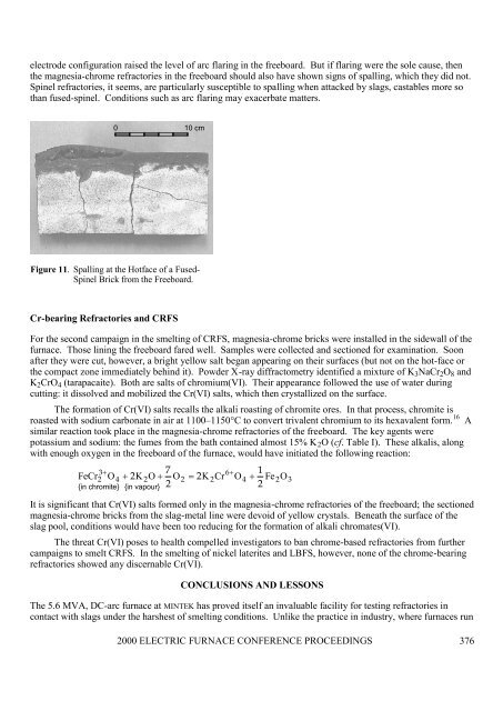
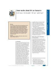
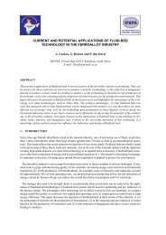
electrode configuration raised the level of arc flaring in the freeboard. But if flaring were the sole cause, thenthe magnesia-chrome refractories in the freeboard should also have shown signs of spalling, which they did not.Spinel refractories, it seems, are particularly susceptible to spalling when attacked by slags, castables more sothan fused-spinel. Conditions such as arc flaring may exacerbate matters.0 10 cmFigure 11. Spalling at the Hotface of a Fused-Spinel Brick from the Freeboard.Cr-bearing Refractories and CRFSFor the second campaign in the smelting of CRFS, magnesia-chrome bricks were installed in the sidewall of thefurnace. Those lining the freeboard fared well. Samples were collected and sectioned for examination. Soonafter they were cut, however, a bright yellow salt began appearing on their surfaces (but not on the hot-face orthe compact zone immediately behind it). Powder X-ray diffractometry identified a mixture of K 3 NaCr 2 O 8 andK 2 CrO 4 (tarapacaite). Both are salts of chromium(VI). Their appearance followed the use of water duringcutting: it dissolved and mobilized the Cr(VI) salts, which then crystallized on the surface.The formation of Cr(VI) salts recalls the alkali roasting of chromite ores. In that process, chromite isroasted with sodium carbonate in air at 1100–1150°C to convert trivalent chromium to its hexavalent form. 16 Asimilar reaction took place in the magnesia-chrome refractories of the freeboard. The key agents werepotassium and sodium: the fumes from the bath contained almost 15% K 2 O (cf. Table I). These alkalis, alongwith enough oxygen in the freeboard of the furnace, would have initiated the following reaction:76+1FeCr 2 O2= 2K2CrO 4 + Fe 2O223+2 O4+ K 2O+{in chromite} {in vapour}It is significant that Cr(VI) salts formed only in the magnesia-chrome refractories of the freeboard; the sectionedmagnesia-chrome bricks from the slag-metal line were devoid of yellow crystals. Beneath the surface of theslag pool, conditions would have been too reducing for the formation of alkali chromates(VI).The threat Cr(VI) poses to health compelled investigators to ban chrome-based refractories from furthercampaigns to smelt CRFS. In the smelting of nickel laterites and LBFS, however, none of the chrome-bearingrefractories showed any discernable Cr(VI).CONCLUSIONS AND LESSONSThe 5.6 MVA, DC-arc furnace at MINTEK has proved itself an invaluable facility for testing refractories incontact with slags under the harshest of smelting conditions. Unlike the practice in industry, where furnaces run32000 ELECTRIC FURNACE CONFERENCE PROCEEDINGS 376
with a freeze lining, there were times when the pilot-scale tests described in this paper did not run with one. Wewere able, therefore, to see how well refractories survived in direct contact with molten slag over a number ofdays. Our examinations of the phases in and morphologies of reaction zones, interpreted in the light ofappropriate phase-chemical theory, provided a means for explaining what happened. Our observations lead usto conclude that—• The dissolution of <strong>refractory</strong> at the hot-face is the principal mechanism by which oxide refractoriessubmerged in a slag bath are eroded. This holds for the smelting of nickel laterite, lead blast-furnace slagand copper reverberatory-furnace slag. The mechanism appears to outweigh any loss of refractorinessbehind the hot-face. There are even indications that differences in structural or physical properties matterlittle.• Dissolution is driven by the low chemical potentials of one or more of the <strong>refractory</strong> oxides in the slags;being unsaturated with MgO, Al 2 O 3 , or Cr 2 O 3 , the slags dissolve these oxides from the refractories.• In fused-spinel bricks in contact with CRFS and magnesia-chrome bricks in contact with either LBFS orslag from nickel laterite, <strong>erosion</strong> is severe. Magnesia bricks appear to offer better resistance to slags fromthe smelting of nickel laterites—which are rich in MgO—than do magnesia-chrome bricks.• Even if a proper freeze lining is not established, cooling panels in the sidewall can be effective in haltingthe <strong>erosion</strong> of <strong>refractory</strong> linings.• Siliceous slags rich in FeO are potentially destructive towards SiC refractories. They oxidize SiC to SiO 2 ,which either dissolves in slag, thereby facilitating the <strong>erosion</strong> of the <strong>refractory</strong>, or establishes anequilibrium with silicon, which reports to the metal as a contaminant. The formation of SiO 2 may alsochange the thermal conductivity of the <strong>refractory</strong> enough to destabilize a freeze lining.• Slags rich in FeO are potentially destructive towards carbon/graphite in refractories. Carbon reduces FeOand certain other oxides to metal. Without graphite protecting them, these refractories are more susceptibleto the corrosive effects of slag.• Unshaped refractories must be properly cured. If this cannot be done, find an alternative.• Spinel refractories lining the freeboard tend to spall. Castables may do so more readily than bricks of fusedspinel.• CRFS produces Cr(VI) in chrome-bearing refractories lining the freeboard. Keep such refractories awayfrom any furnace smelting slags with even a few per cent K 2 O or Na 2 O.ACKNOWLEDGEMENTSI thank two colleagues, Johan Nell and Rodney Jones, for reading through and commenting on a draft of thispaper. I am indebted to my colleagues in the Pyrometallurgy Division for passing countless samples ofrefractories on to me for study; in particular, my thanks go to Glen Denton, Herman Lagendijk, Genine Assisand Mata Botima. I am grateful to MINTEK for its consent to the publication of this paper.REFERENCES1. R.T. Jones, T.R. Curr and N.A. Barcza, “Development of plasma furnace technology at <strong>Mintek</strong>,” Miner.Ind. Int., No. 1017, March 1994, pp. 25–31.2. R.T. Jones, D.A. Hayman and G.M. Denton, “Recovery of cobalt, nickel, and copper from slags, usingDC-arc furnace technology,” in C.A. Pickles, P.J. Hancock and J.R. Wynnyckyj (eds) Challenges inProcess Intensification, Proceedings of the International Symposium, Canadian Institute of Mining,Metallurgy and Petroleum, Montreal, 1996, pp. 451–66.2000 ELECTRIC FURNACE CONFERENCE PROCEEDINGS 377