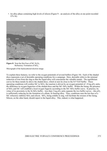
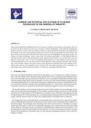
combination would have imposed a steadier temperature on the hot-face. The effect would have minimizedslag penetration and the attendant disintegration of <strong>refractory</strong> behind the hot-face; the hot-face itself would havereceded (through dissolution) until its temperature matched the liquidus of the slag. In the first and thirdcontexts, the hot-face of the castable would either have been subjected to greater fluctuations in temperatures, ornot have had the benefit of forced cooling. The slag in the pores would have set up a zone of disintegration thatmarks the hot-face as indistinct.Alumina, Alumina-Chrome and LBFS or CRFSThe two combinations are an alumina castable in contact with CRFS and an alumina-chrome rammable incontact with LBFS (tables II and III). The castable contained over 98% Al 2 O 3 + MgO; the rammable,~4% SiO 2 . Both refractories lined the sidewall against the slag bath and the freeboard, and both shieldedcooling panels.The project investigators installed these refractories with different purposes in mind. Their intention wasfor nothing of the alumina-chrome rammable to remain, which is what happened, save for small fragmentsisolated in a corner of the lining. The alumina <strong>refractory</strong> was meant to survive, which it did: ~3 cm of the liningremained against the panels. Sections through samples of the alumina castable revealed the slag to havepenetrated ~1 cm of the <strong>refractory</strong>. On the other hand, a section through the alumina-chrome fragment revealedlittle penetration—indeed, the slag encountered the <strong>refractory</strong> at a fairly sharp interface; the hot-face was welldefinedacross matrix and aggregates.How do these results square with phase-chemical theory? Both refractories, being essentially alumina,would have been incompatible with either slag, which contain less than 10% Al 2 O 3 . The unsaturated slagwould have dissolved Al 2 O 3 from the refractories. The alumina-chrome <strong>refractory</strong> would have been furtherdisadvantaged by Cr 2 O 3 and SiO 2 . That the alumina castable survived as it did, even that a fragment ofalumina-chrome <strong>refractory</strong> survived, attests to the efficacy of the cooling panels, if not the properties of therefractories. The fragment of alumina-chrome <strong>refractory</strong> was particularly revealing. Over much of thesidewall, its chemical composition, along with the control of energy flux through the wall, allowed slag to erodethe <strong>refractory</strong>; yet in the fragment, there was little penetration of the matrix by slag and no sign of anyweakening of <strong>refractory</strong> behind the hot-face. Erosion occurred by the dissolution of <strong>refractory</strong> at the hot-face.Because the fragment survived, we would surmise that the lining in that vicinity probably benefited from bettercooling and less turbulence.Silicon Carbide and LBFS or CRFSNitride-bonded silicon carbide (SiC-Si 3 N 4 ) lined the sidewall in contact with the slag bath of three campaigns.Investigators reasoned that the high thermal conductivity of the <strong>refractory</strong> (see Table II) would make it easier toestablish a freeze lining, and so preserve the <strong>refractory</strong>. The unexpected happened, however. Whereas thelining survived largely intact after 25 days of smelting CRFS at ~1550°C, it disappeared after 18 days ofsmelting LBFS at ~1400°C. Clearly, for a time at least, a freeze lining did not exist. It was only afterinvestigators pointed out measures taken to prepare the lining for the LBFS campaign that we could make senseof this result. We now believe the destruction of the SiC lining in that campaign to have been initiated during a36 hour period prior to commencement. Because the bricks did not fit tightly together, the gaps between themwere filled with a SiC mortar, which required curing. Burners were lit. They would have oxidized SiC to SiO 2 ,which would subsequently have dissolved readily in slag. The lining would have eroded fairly quickly.Had this not happened, however, the <strong>refractory</strong> would still have faced another destructive process—albeita far milder one. The evidence appeared in a sample from the CRFS campaign. Close examination of<strong>refractory</strong> near the hot-face identified three features not present in the virgin <strong>refractory</strong>:• Specs of carbon in the matrix of the <strong>refractory</strong>.• A layer of silica (SiO 2 ) on the surfaces of many particles of SiC (Figure 8). This would suggest thatconditions in the furnace were sufficiently oxidizing for SiO 2 to form from SiC.2000 ELECTRIC FURNACE CONFERENCE PROCEEDINGS 372
• An alloy phase containing high levels of silicon (Figure 9—an analysis of the alloy at one point recorded15% Si).SiCporeSiO 2 -3% CSi 3 O 0.2 N 3.10 100 µmFigure 8. Near the Hot-Face of SiC-Si 3 N 4Refractory: Formation of SiO 2 .Micrograph of the backscattered-electron image.To explain these features, we refer to the oxygen potentials of several buffers (Figure 10). Each of the shadeddiscs represents a set of desirable operating conditions for a campaign. Here, desirable refers to the minimalreduction of iron from the slag so that the liquid alloy will concentrate the valuable metals. The equilibriumcurves for these metals lie above the shaded discs, which in turn lie close to the Fe 0 -FeO buffer. Theseoperating conditions will oxidize SiC to SiO 2 : the reaction is driven by an oxygen potential of ~8 log pO 2 units,the difference in oxygen fugacities of the shaded discs and the SiC-SiO 2 buffer. Within the lining, the presenceof SiO 2 and SiC will establish a local oxygen fugacity according to the SiC-SiO 2 buffer curve. In practice, byvirtue of its proximity to the Si-SiO 2 buffer—less than 2 log pO 2 units separate the two buffer curves—this pO 2is sufficiently reducing for the formation of a dilute, Si-bearing alloy. Thus, conditions near the hot-face of aSiC <strong>refractory</strong> stabilize SiO 2 and silicon. SiO 2 , being soluble in slag, will facilitate the <strong>erosion</strong> of the lining.Silicon, on the other hand, should report to the liquid alloy. This, indeed, is what happened.2000 ELECTRIC FURNACE CONFERENCE PROCEEDINGS 373