
Create successful ePaper yourself
Turn your PDF publications into a flip-book with our unique Google optimized e-Paper software.
Danaher Motion Superior Electric Installation<br />
3.2.1. Motor Connections<br />
All motor connections are made via the 6-pin connector, part number<br />
218397-006. Pin assignments for this connector are given below. Motor<br />
connections are shown in the next figure.<br />
Pin Assignment<br />
1 M1 (Phase A)<br />
2 M3 (Phase A)<br />
3 M4 (Phase B)<br />
4 M5 (Phase B)<br />
Motor Phase A is M1 and M3. Motor Phase B is M4 and M5. The<br />
motor frame MUST be grounded.<br />
Cabling from the drive to the motor should be with a shielded, twistedpair<br />
cable. As a guideline, the wires for each motor phase should be<br />
twisted about six times per foot.<br />
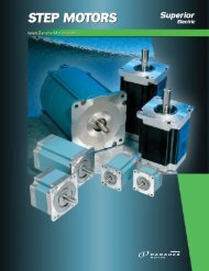
Danaher Motion Superior Electric offers the following motor cable<br />
configurations. These cables have unterminated leads on both ends.<br />
Length Part Number<br />
10 ft (3 m) 216022-031<br />
25 ft (7.6 m) 216022-032<br />
50 ft (15.2 m) 216022-033<br />
75 ft (22.8 m) 216022-034<br />
SLO-SYN <strong>SS2000</strong><strong>MD7</strong> & <strong>SS2000</strong><strong>MD7</strong>-128 5