Create successful ePaper yourself
Turn your PDF publications into a flip-book with our unique Google optimized e-Paper software.
Hardware Specifications Danaher Motion Superior Electric<br />
4.7. Signal Specifications<br />
4.7.1. Connector Pin Assignments<br />
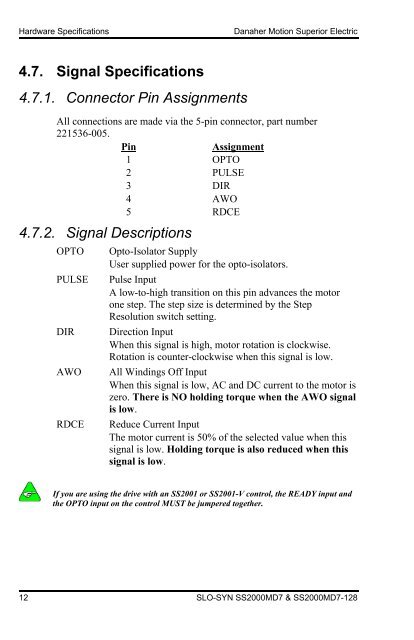
All connections are made via the 5-pin connector, part number<br />
221536-005.<br />
Pin Assignment<br />
1 OPTO<br />
2 PULSE<br />
3 DIR<br />
4 AWO<br />
5 RDCE<br />
4.7.2. Signal Descriptions<br />
OPTO Opto-Isolator Supply<br />
User supplied power for the opto-isolators.<br />
PULSE Pulse Input<br />
A low-to-high transition on this pin advances the motor<br />
one step. The step size is determined by the Step<br />
Resolution switch setting.<br />
DIR Direction Input<br />
When this signal is high, motor rotation is clockwise.<br />
Rotation is counter-clockwise when this signal is low.<br />
AWO All Windings Off Input<br />
When this signal is low, AC and DC current to the motor is<br />
zero. There is NO holding torque when the AWO signal<br />
is low.<br />
RDCE Reduce Current Input<br />
The motor current is 50% of the selected value when this<br />
signal is low. Holding torque is also reduced when this<br />
signal is low.<br />
If you are using the drive with an SS2001 or SS2001-V control, the READY input and<br />
the OPTO input on the control MUST be jumpered together.<br />
12 SLO-SYN <strong>SS2000</strong><strong>MD7</strong> & <strong>SS2000</strong><strong>MD7</strong>-128


