
You also want an ePaper? Increase the reach of your titles
YUMPU automatically turns print PDFs into web optimized ePapers that Google loves.
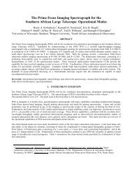
Danaher Motion Superior Electric Hardware Specifications<br />
4.5. Current Settings<br />
The proper current setting for each motor is shown on the individual<br />
torque vs. speed curve. Use this current level to obtain the torque<br />
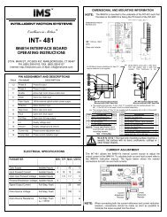
shown. The access hole for the switches that set the motor current level<br />
is located on the back of the unit (see next figure). Switches 1 through 6<br />
are used to select the current level. Select the desired operating current<br />
by setting the appropriate switch to position 1 (ON). The OFF position<br />
is labeled "0." Only one switch should be ON. If two or more switches<br />
are ON, the one selecting the highest current level is the active switch.<br />
The switch settings are:<br />
Position Current (amps)<br />
None 1.0<br />
1 2.0<br />
2 3.0<br />
3 4.0*<br />
4 5.0*<br />
5 6.0*<br />
6 7.0*<br />
* Heat sinking is recommended at current settings of 4 amps or<br />
higher. The drive case temperature MUST NOT exceed 70° C.<br />
4.6. Step Resolution<br />
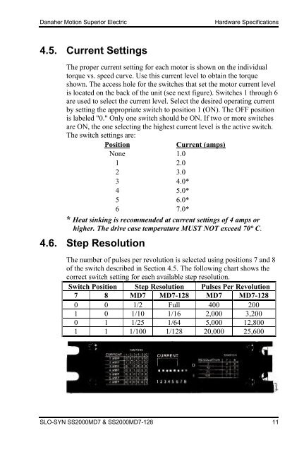
The number of pulses per revolution is selected using positions 7 and 8<br />
of the switch described in Section 4.5. The following chart shows the<br />
correct switch setting for each available step resolution.<br />
Switch Position Step Resolution Pulses Per Revolution<br />
7 8 <strong>MD7</strong> <strong>MD7</strong>-128 <strong>MD7</strong> <strong>MD7</strong>-128<br />
0 0 1/2 Full 400 200<br />
1 0 1/10 1/16 2,000 3,200<br />
0 1 1/25 1/64 5,000 12,800<br />
1 1 1/100 1/128 20,000 25,600<br />
SLO-SYN <strong>SS2000</strong><strong>MD7</strong> & <strong>SS2000</strong><strong>MD7</strong>-128 11