CAN interface for FMS Introduction - Scania
CAN interface for FMS Introduction - Scania
CAN interface for FMS Introduction - Scania

You also want an ePaper? Increase the reach of your titles
YUMPU automatically turns print PDFs into web optimized ePapers that Google loves.
<strong>Introduction</strong><br />
<strong>CAN</strong> <strong>interface</strong> <strong>for</strong> <strong>FMS</strong><br />
This document contains in<strong>for</strong>mation on the <strong>FMS</strong> standard, which is an open common<br />
<strong>interface</strong> produced by many manufacturers of rigid trucks. <strong>FMS</strong> 2.0 is also supported<br />
starting in May 2011.<br />
<strong>Scania</strong>'s <strong>FMS</strong> <strong>interface</strong> is referred to in this document as RTG, and the bodybuilder<br />
links their own <strong>FMS</strong> network to the control unit via a connector.<br />
• Up to and including January 2009, the connection was made via connector C471<br />
• From February 2009 onwards, the connection is made via connector C137<br />
Connectors C137 and C471 are located next to the central electric unit in the instrument<br />
panel.<br />
Chassis serial number limits <strong>for</strong> the different connections are indicated later in this<br />
document.<br />
IMPORTANT!<br />
No other connector or other <strong>CAN</strong> bus may be connected. An incorrect connection<br />
could cause the normal functions of the rigid truck to behave irrationally. The rigid<br />
truck may even stop and need to be towed.<br />
11:90-02 Issue 5 en-GB 1 (80)<br />
© <strong>Scania</strong> CV AB 2012, Sweden<br />
<strong>Introduction</strong><br />
More in<strong>for</strong>mation on the <strong>FMS</strong> standard can be found at www.fms-standard.com.
<strong>CAN</strong> <strong>interface</strong> <strong>for</strong> <strong>FMS</strong><br />
Chassis serial number limits <strong>for</strong> <strong>FMS</strong> 2.0 support<br />
Vehicle production period<br />
Production site Chassis serial number<br />
2011-04-28 -<br />
Södertälje 2 065 555 -<br />
Zwolle 5 266 558 -<br />
Angers 9 159 407 -<br />
São Bernardo do Campo 3 685 031 -<br />
Abbreviations<br />
Abbreviation Explanation<br />
<strong>CAN</strong> Controller Area Network<br />
COO Koordinator<br />
ECU Electronic Control Unit<br />
<strong>FMS</strong> Fleet Management System<br />
RTG Road Transport In<strong>for</strong>matics Gateway<br />
ICL Instrument Cluster System<br />
PGN Parameter Group Number<br />
TCO Tachograph<br />
EBS Electronic Brake System<br />
DTCO Digital tachograph with remote driver card in<strong>for</strong>mation downloading<br />
© <strong>Scania</strong> CV AB 2012, Sweden<br />
<strong>Introduction</strong><br />
11:90-02 Issue 5 en-GB 2 (80)
<strong>CAN</strong> <strong>interface</strong> <strong>for</strong> <strong>FMS</strong><br />
Requirements <strong>for</strong> <strong>CAN</strong> communication with<br />
the vehicle<br />
This section lists the requirements <strong>for</strong> <strong>CAN</strong> communication with the RTG control<br />
unit on the external <strong>CAN</strong> bus. SAE J1939 <strong>for</strong>ms the basis of the protocol, but large<br />
parts are not implemented. These parts are SAE J1939-81 (Network Management),<br />
main part of SAE J1939-73 (Diagnostics) and parts of SAE J1939-21 (Data Link<br />
Layer).<br />
SAE J1939-81 Network Management<br />
The address space in a <strong>Scania</strong> vehicle is static. Because of this, there is no need <strong>for</strong><br />
the Network Management described in SAE J1939-81.<br />
• Fixed addressing is used in accordance with Preferred addresses <strong>for</strong> Industry<br />
group 0, Global and Industry group 1, On-highway Equipment.<br />
• Source addresses <strong>for</strong> equipment which does not normally belong to the vehicle<br />
follow the requirements in J1939, ISO 11992 or OBD/EOBD.<br />
© <strong>Scania</strong> CV AB 2012, Sweden<br />
Requirements <strong>for</strong> <strong>CAN</strong> communication with the vehicle<br />
11:90-02 Issue 5 en-GB 3 (80)
<strong>CAN</strong> <strong>interface</strong> <strong>for</strong> <strong>FMS</strong><br />
SAE J1939-21 Data Link Layer<br />
SAE J1939-21 defines five message types:<br />
• Commands - Not supported.<br />
• Requests - Not supported.<br />
• Broadcast/Response - All available in<strong>for</strong>mation is sent periodically.<br />
• Acknowledgement - Not supported.<br />
• Group Functions - Proprietary messages och Multipacket messages, TP.CM,<br />
TP.DT, are supported.<br />
Note:<br />
According to section 5.2.1 SAE J1939-21, revised version July 1998, priority bits in<br />
message identifiers must be filtered out and ignored by the receivers.<br />
General guidelines<br />
• Control units connected to a <strong>CAN</strong> bus must be able to handle up to 100% <strong>CAN</strong><br />
bus load with the correct messages with no significant functional limitations or<br />
malfunctions.<br />
• Under normal circumstances the <strong>CAN</strong> bus load should never exceed 80%.<br />
• Avoid closing control loops over the <strong>CAN</strong> because the guaranteed access time is<br />
relatively long and fast control loops require a lot of bandwidth. If closed control<br />
loops over the <strong>CAN</strong> are still required, then they must be fully capable of sending<br />
the necessary <strong>CAN</strong> messages using only half the transmission frequency.<br />
IMPORTANT!<br />
The bodybuilder is responsible <strong>for</strong> ensuring that the external <strong>CAN</strong> bus is used correctly.<br />
© <strong>Scania</strong> CV AB 2012, Sweden<br />
Requirements <strong>for</strong> <strong>CAN</strong> communication with the vehicle<br />
11:90-02 Issue 5 en-GB 4 (80)
<strong>CAN</strong> <strong>interface</strong> <strong>for</strong> <strong>FMS</strong><br />
Connectors and cables<br />
• <strong>Scania</strong> does not use SAE J1939 connectors.<br />
• <strong>Scania</strong> uses twisted pair cables (twisted 40 times per metre) with no shield or<br />
sheath. The electrical properties (resistance, impedance, capacitance etc.) are defined<br />
in SAE J1939-15 Physical Layer Light.<br />
• <strong>Scania</strong> uses a cross-section of 0.75 mm 2 <strong>for</strong> cables inside the cab and 1.5 mm 2 on<br />
the frame. <strong>CAN</strong> connectors (and ECU pins) outside the cab should preferably be<br />
gold-plated.<br />
• The following colours and markings apply to the external <strong>CAN</strong> bus cables:<br />
<strong>CAN</strong>_H must be blue and <strong>CAN</strong>_L must be white. In order to avoid misunderstanding<br />
it is important that the cables retain their colour <strong>for</strong> the lifetime of the<br />
vehicle. <strong>CAN</strong> low should be marked as <strong>CAN</strong>_L and <strong>CAN</strong> high as <strong>CAN</strong>_H.<br />
© <strong>Scania</strong> CV AB 2012, Sweden<br />
Connectors and cables<br />
11:90-02 Issue 5 en-GB 5 (80)
Connection to RTG<br />
Connector C137<br />
<strong>CAN</strong> <strong>interface</strong> <strong>for</strong> <strong>FMS</strong><br />
Vehicle production period<br />
Production site Chassis serial number<br />
2009-02-09 -<br />
Södertälje 2 046 610 -<br />
Zwolle 5 225 592 -<br />
Angers 9 141 661 -<br />
São Bernardo do Campo 3 644 908 -<br />
Signal Pin Remarks<br />
Connection 15 (Ubat) 10<br />
Connection 30 (24 V) 12<br />
Connection 31 (24 V ground) 1<br />
<strong>CAN</strong> low 9<br />
<strong>CAN</strong> high 6<br />
<strong>CAN</strong> low<br />
<strong>CAN</strong> high<br />
5<br />
8<br />
Not supported by <strong>Scania</strong><br />
Connection 15R (Ubat) 11<br />
12 V voltage 3 Only if vehicle is equipped with a 12 V<br />
12 V ground 4 voltage converter<br />
Reserved 2<br />
Reserved 7<br />
© <strong>Scania</strong> CV AB 2012, Sweden<br />
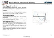
1 4 7 10<br />
2 5 8 11 952<br />
3 6 9 12307<br />
Pin numbering on connector C137<br />
Connection to RTG<br />
11:90-02 Issue 5 en-GB 6 (80)<br />
C137<br />
1. Fuse <strong>for</strong> RTG<br />
1<br />
E51<br />
RTG<br />
307 953
Connector C471<br />
<strong>CAN</strong> <strong>interface</strong> <strong>for</strong> <strong>FMS</strong><br />
Vehicle production period<br />
Production site Chassis serial number<br />
- 2009-02-08<br />
Södertälje - 2 046 609<br />
Zwolle - 5 225 591<br />
Angers - 9 141 660<br />
São Bernardo do Campo - 3 644 907<br />
Connect <strong>CAN</strong> high to connector C471, pin 2, and <strong>CAN</strong> low to connector C471, pin 1.<br />
© <strong>Scania</strong> CV AB 2012, Sweden<br />
Connection to RTG<br />
11:90-02 Issue 5 en-GB 7 (80)
Topology<br />
<strong>CAN</strong> <strong>interface</strong> <strong>for</strong> <strong>FMS</strong><br />
The topology is essentially a bus cable with the nodes connected to the <strong>CAN</strong> bus with<br />
at least 0.1 metre between each node.<br />
• The length of the cables must not exceed 30 metres (main cable) between the connector<br />
in the truck and the control unit with the other termination resistor.<br />
• If more than one control unit is connected, the length of the cables between the<br />
main cable and control unit should not exceed 3 metres.<br />
• The cables should be as short as possible to minimise the effect of electromagnetic<br />
interference.<br />
• The number of control units in the external <strong>FMS</strong> network should not exceed 9.<br />
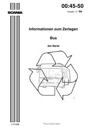
The figure shows the principle of the external <strong>FMS</strong> network topology.<br />
© <strong>Scania</strong> CV AB 2012, Sweden<br />
Connection to RTG<br />
11:90-02 Issue 5 en-GB 8 (80)<br />
< 30 m<br />
RTG C137 ECU X<br />
< 3 m<br />
> 0.1 m<br />
1 2<br />
1. RTG control unit with termination resistor<br />
ECU Z ECU Y<br />
2. <strong>FMS</strong> control unit in the bodywork with termination resistors<br />
307 950
Termination resistors<br />
<strong>CAN</strong> <strong>interface</strong> <strong>for</strong> <strong>FMS</strong><br />
The <strong>CAN</strong> bus cable must be connected using a 120 Ohm resistor at each end in accordance<br />
with SAE J1939-15 Physical Layer.<br />
Depending on the other control units connected to the <strong>CAN</strong> bus, there must be a 120<br />
Ohm termination resistor in the control unit which is connected to the <strong>FMS</strong> <strong>interface</strong><br />
<strong>for</strong> bodybuilders.<br />
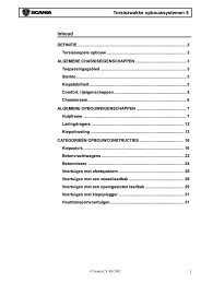
If the control unit is not equipped with an internal termination resistor, an external<br />
termination resistor must be connected as close to the control unit as possible (see<br />
illustration).<br />
© <strong>Scania</strong> CV AB 2012, Sweden<br />
Termination resistors<br />
<strong>CAN</strong> High<br />
11:90-02 Issue 5 en-GB 9 (80)<br />
RTG<br />
<strong>CAN</strong> High<br />
<strong>CAN</strong> Low<br />
R<br />
C137<br />
R<br />
ECU X<br />
<strong>CAN</strong> Low<br />
1 2<br />
3<br />
1. RTG with internal termination resistor<br />
2. Connectors that constitute a <strong>interface</strong> <strong>for</strong> bodybuilders<br />
3. Termination resistor fitted in the control unit connector<br />
6<br />
9<br />
310 812
<strong>CAN</strong> <strong>interface</strong> <strong>for</strong> <strong>FMS</strong><br />
Termination of an external <strong>CAN</strong> bus<br />
So that <strong>CAN</strong> communication can work without interference, there must be a 120<br />
Ohm termination resistor at each end of the <strong>CAN</strong> bus. Check that there is a termination<br />
resistor at each end of the <strong>CAN</strong> bus using a multimeter. The resistance should<br />
be 60 Ohm (two 120 Ohm resistors connected in parallel).<br />
A number of different systems can be connected to the cable harness of the external<br />
<strong>CAN</strong> bus. Certain systems have a built-in termination resistor and others are unterminated.<br />
The table shows when there is to be a termination resistor in connector C137 or in the<br />
control unit connected to C137.<br />
Systems in the vehicle Termination resistor in<br />
DTCO <strong>Scania</strong> Communicator<br />
C200<br />
RTG<br />
© <strong>Scania</strong> CV AB 2012, Sweden<br />
the control unit connected<br />
to C137<br />
No No Yes Yes<br />
Yes No Yes No<br />
Yes Yes Yes No<br />
No Yes Yes Yes<br />
Yes No No Yes<br />
Yes Yes No Yes<br />
Termination resistors<br />
11:90-02 Issue 5 en-GB 10 (80)
<strong>CAN</strong> <strong>interface</strong> <strong>for</strong> <strong>FMS</strong><br />
Fault validation of communication (Time-<br />
Out)<br />
Avoid <strong>CAN</strong> communication when the starter key is in the lock or radio positions.<br />
Also avoid <strong>CAN</strong> communication during the start sequence of the control units connected<br />
to the external <strong>CAN</strong> bus.<br />
During normal operation, when the starter key is in the drive position, a message<br />
should not be validated as missed (time-out) until at least 5 times the message period<br />
time. A longer fault validation time is permitted.<br />
During the engine start sequence, when the starter motor is turning, the supply voltage<br />
can be extremely low. Because of this, communication from the RTG control<br />
unit cannot be guaranteed during this sequence. For this reason, no fault codes related<br />
to <strong>CAN</strong> communication with the RTG control unit should be set when the system<br />
voltage is under 18 V.<br />
When the starter key is turned to the drive position, the RTG control unit starts sending<br />
messages within 10,000 ms. A message sent from the <strong>FMS</strong> control unit cannot<br />
be considered missed until after 10,000 ms + 5 x the message period time. Example:<br />
If a message has a period time of 100 ms it cannot be considered missed until after<br />
10,000 + 5 x 100 = 10,500 ms. Longer fault validation times are permitted.<br />
© <strong>Scania</strong> CV AB 2012, Sweden<br />
Fault validation of communication (Time-Out)<br />
11:90-02 Issue 5 en-GB 11 (80)
<strong>CAN</strong> <strong>interface</strong> <strong>for</strong> <strong>FMS</strong><br />
Summary of <strong>CAN</strong> messages<br />
The following is a summary of the messages supported by the <strong>CAN</strong> <strong>interface</strong> <strong>for</strong><br />
<strong>FMS</strong>.<br />
<strong>CAN</strong> messages which are sent to the external <strong>CAN</strong><br />
bus from the RTG <strong>interface</strong><br />
© <strong>Scania</strong> CV AB 2012, Sweden<br />
Summary of <strong>CAN</strong> messages<br />
Message sent from vehicle Identifier (Hex) Specification <strong>FMS</strong> standard <strong>Scania</strong> <strong>FMS</strong> <strong>interface</strong><br />
01.00 02.00<br />
Alarm Status Proprietarya 18 FF B4 1D <strong>Scania</strong> X<br />
Ambient Conditions - K 18 FE F5 27 SAEJ1939-71 X X<br />
Cab Illumination Message - ICL 18 D0 FF 17 SAEJ1939-71 X<br />
Coordinator General In<strong>for</strong>mation - K 0C FF B0 27 <strong>Scania</strong> X<br />
Crash Occurred - AB 18 FF FD 64 <strong>Scania</strong> X<br />
Cruise Control/Vehicle Speed 18 FE F1 00 SAEJ1939-71 X X X<br />
CUV In<strong>for</strong>mation - V 18 FF B1 1E <strong>Scania</strong> X<br />
Dash Display - K 18 FE FC 27 SAEJ1939-71 X X X<br />
Driver’s Identification (DI_cyclic) - <strong>FMS</strong> (transmitted using BAM) 18 EC FF 25/18 EB FF 25 SAEJ1939-71 X X<br />
EBC2 Wheel Speed Proprietary 0C FF 19 0B <strong>Scania</strong> X<br />
Electronic Brake Controller 1 (EBC1) - A 18 F0 01 0B SAEJ1939-71 X<br />
Electronic Engine Controller 1 (EEC1) - E 0C F0 04 00 SAEJ1939-71 X X X<br />
Electronic Engine Controller 2 (EEC2) - E 0C F0 03 00 SAEJ1939-71 X X X<br />
Electronic Retarder Controller1 (ERC1) - RD 18 F0 00 10 SAEJ1939-71 X<br />
Electronic Retarder Controller1 (ERC1) - REX 18 F0 00 29 SAEJ1939-71 X<br />
Electronic Transmission Controller 2 (ETC2) -T 18 F0 05 03 SAEJ1939-71 X<br />
Engine Configuration (EngineConfig) - E (transmitted using BAM) 18 EC FF 00/18 EB FF 00 SAEJ1939-71 X<br />
Engine Fluid Level/Pressure 1 - K 18 FE EF 27 SAEJ1939-71 X<br />
11:90-02 Issue 5 en-GB 12 (80)
<strong>CAN</strong> <strong>interface</strong> <strong>for</strong> <strong>FMS</strong><br />
Engine Hours, Revolutions - E 18 FE E5 00 SAEJ1939-71 X X X<br />
Engine Temperature 1 - E 18 FE EE 00 SAEJ1939-71 X X X<br />
Error Message - <strong>FMS</strong> 18FFFF25 <strong>Scania</strong> X<br />
<strong>FMS</strong>-standard Interface Identity/Capabilities (<strong>FMS</strong> Std Interface) - <strong>FMS</strong> 1C FD D1 25 SAEJ1939-71 X X X<br />
Fuel Consumption - E 18 FE E9 00 SAEJ1939-71 X X X<br />
Fuel Economy - E 18 FE F2 00 SAEJ1939-71 X X<br />
General Purpose Message 1 - E 18 FF 60 00 <strong>Scania</strong> X<br />
High Resolution Fuel Consumption (Liquid) (HRLFC) - <strong>FMS</strong> 18 FD 09 25 SAEJ1939-71 X<br />
High Resolution Vehicle Distance - TCO 18 FE C1 EE SAEJ1939-71 X X X<br />
Inlet/Exhaust Conditions 1 - E 18 FE F6 00 SAEJ1939-71 X<br />
PTO Drive Engagementb N/A SAEJ1939-71 X<br />
PTO In<strong>for</strong>mation Proprietary - K 18 FF 90 27 <strong>Scania</strong> X<br />
Service In<strong>for</strong>mation (ServiceIn<strong>for</strong>mation) - <strong>FMS</strong> 18FEC025 SAEJ1939-71 X X X<br />
Tachograph - TCO1 0C FE 6C EE SAEJ1939-71 X X X<br />
Time/Date (TimeDate) - ICL 18 FE E6 17 SAEJ1939-71 X<br />
Vehicle Identification (VehicleId) - <strong>FMS</strong> (transmitted using BAM) 18ECFF25/18EBFF25 SAEJ1939-71 X X X<br />
Vehicle Weight (Vehicle Weight) - <strong>FMS</strong> 18 FE EA 25 SAEJ1939-71 X X X<br />
Wheel Brake Lining Remaining In<strong>for</strong>mation<br />
(EBC4WheelBrakeLiningRemainingInf) - A c<br />
1C FE AC 0B SAEJ1939-71 X<br />
a. Only sent if the vehicle has an alarm (LAS).<br />
b. According to the standard, either PTO Drive Engagement or CCVS is sent. <strong>Scania</strong> sends CCVS.<br />
c. Only sent if the vehicle is equipped with EBS.<br />
© <strong>Scania</strong> CV AB 2012, Sweden<br />
Summary of <strong>CAN</strong> messages<br />
Message sent from vehicle Identifier (Hex) Specification <strong>FMS</strong> standard <strong>Scania</strong> <strong>FMS</strong> <strong>interface</strong><br />
01.00 02.00<br />
11:90-02 Issue 5 en-GB 13 (80)
<strong>CAN</strong> <strong>interface</strong> <strong>for</strong> <strong>FMS</strong><br />
Detailed description of <strong>CAN</strong> messages<br />
The following tables use the concepts below:<br />
• Not defined: Not defined in SAE J1939<br />
• Not used: Defined in SAE 1939 but not used by <strong>Scania</strong><br />
For the content of messages with parameter group numbers (PGN) specified by<br />
<strong>Scania</strong>:<br />
• Not defined: Not defined by <strong>Scania</strong><br />
© <strong>Scania</strong> CV AB 2012, Sweden<br />
Detailed description of <strong>CAN</strong> messages<br />
11:90-02 Issue 5 en-GB 14 (80)
<strong>CAN</strong> <strong>interface</strong> <strong>for</strong> <strong>FMS</strong><br />
Alarm Status Propietary - AL<br />
Identifier: 18 FF B4 1D<br />
Transmission interval: 1,000 ms.<br />
© <strong>Scania</strong> CV AB 2012, Sweden<br />
Detailed description of <strong>CAN</strong> messages<br />
Byte Bit Length Explanation State Resolution Limits Note<br />
1 1 4 Alarm status<br />
Alarm unset 0000<br />
Alarm set 0001<br />
Alarm triggered 0010<br />
Silent alarm triggered 0011<br />
Alarm set perimeter 0100<br />
Ferry mode 0101<br />
Alarm unset with XPDR failed 0110<br />
Alarm unset with XPDR successed 0111<br />
Work alert 1000<br />
Alarm test 1001<br />
Alarm passive set 1010<br />
Not defined 1100..1101<br />
Reserved 1110<br />
Don't care/take no action 1111<br />
5 4 Not defined<br />
2..8 Not defined<br />
11:90-02 Issue 5 en-GB 15 (80)
Ambient Conditions<br />
Identifier: 18 FE F5 27<br />
Transmission interval: 1,000 ms<br />
Always sent from BWS.<br />
<strong>CAN</strong> <strong>interface</strong> <strong>for</strong> <strong>FMS</strong><br />
© <strong>Scania</strong> CV AB 2012, Sweden<br />
Detailed description of <strong>CAN</strong> messages<br />
Byte Bit Length Explanation State Resolution Limits Note<br />
1 1 8 Barometric pressure 0.5 kPa/bit 0 to 125 kPa<br />
Error indicator FE<br />
Not available FF<br />
2 Not used<br />
4 1 16 Ambient air temperature 0.03125°C/bit -273 to +1 735.0 °C<br />
Error indicator FExx<br />
Not available FFxx<br />
6..8 Not used<br />
11:90-02 Issue 5 en-GB 16 (80)
Cab Illumination Message<br />
Identifier: 18 D0 FF 17<br />
Transmission interval: 100 ms<br />
Always sent from BWS.<br />
<strong>CAN</strong> <strong>interface</strong> <strong>for</strong> <strong>FMS</strong><br />
© <strong>Scania</strong> CV AB 2012, Sweden<br />
Detailed description of <strong>CAN</strong> messages<br />
Byte Bit Length Explanation State Resolution Limits Note<br />
1 1 8 Requested illumination percentage 0.4% 0 to 100%<br />
Error FEh<br />
Not available FFh<br />
2..8 Not defined<br />
11:90-02 Issue 5 en-GB 17 (80)
<strong>CAN</strong> <strong>interface</strong> <strong>for</strong> <strong>FMS</strong><br />
Coordinator General In<strong>for</strong>mation<br />
Identifier: 0C FF B0 27<br />
Transmission interval: 200 ms 1<br />
Always sent from BWS.<br />
1. The normal transmission interval is 200 ms. If certain parameters are modified, the transmission<br />
interval is 10 ms.<br />
© <strong>Scania</strong> CV AB 2012, Sweden<br />
Detailed description of <strong>CAN</strong> messages<br />
Byte Bit Length Explanation State Resolution Limits Note<br />
1..3 Not defined<br />
4 1..2 Not defined<br />
3 2 Engine stop switch<br />
Engine stop switch not activated 00<br />
Engine stop switch activated 01<br />
Error 10<br />
Not available 11<br />
5 2 Not defined<br />
7 2 0,8 bar parking brake<br />
0,8 bar parking brake not set 00<br />
0,8 bar parking brake set 01<br />
Error indicator 10<br />
Not available or not installed 11<br />
5 1..6 Not defined<br />
7 2 Gearbox in reverse A<br />
Gearbox not in reverse 00<br />
Gearbox in reverse 01<br />
Error 10<br />
11:90-02 Issue 5 en-GB 18 (80)
<strong>CAN</strong> <strong>interface</strong> <strong>for</strong> <strong>FMS</strong><br />
Not available 11<br />
6..8 Not defined<br />
A: In<strong>for</strong>mation is taken from ETC2 on all gearboxes apart from manual gearboxes<br />
without a torque converter.<br />
© <strong>Scania</strong> CV AB 2012, Sweden<br />
Detailed description of <strong>CAN</strong> messages<br />
Byte Bit Length Explanation State Resolution Limits Note<br />
11:90-02 Issue 5 en-GB 19 (80)
Crash Occured<br />
Identifier: 18 FF FD 64<br />
Transmission interval: 1,000 ms<br />
<strong>CAN</strong> <strong>interface</strong> <strong>for</strong> <strong>FMS</strong><br />
Only sent from BWS if Crash Safety System (CSS) is installed.<br />
© <strong>Scania</strong> CV AB 2012, Sweden<br />
Detailed description of <strong>CAN</strong> messages<br />
Byte Bit Length Explanation State Resolution Limits Note<br />
1..8 Not used<br />
11:90-02 Issue 5 en-GB 20 (80)
<strong>CAN</strong> <strong>interface</strong> <strong>for</strong> <strong>FMS</strong><br />
Cruise Control/Vehicle Speed<br />
Identifier: 18 FE F1 00<br />
Transmission interval: 100 ms<br />
Always sent from BWS.<br />
© <strong>Scania</strong> CV AB 2012, Sweden<br />
Detailed description of <strong>CAN</strong> messages<br />
Byte Bit Length Explanation State Resolution Limits Note<br />
1 1..2 Not used<br />
3 2 Parking brake switch A<br />
Parking brake not set 00<br />
Parking brake set 01<br />
Error indicator 10<br />
Not available or not installed 11<br />
5..6 Not used<br />
7..8 Not defined<br />
2 1 16 Wheel-based vehicle speed 1/256 km/h per bit 0 to 251 km/h<br />
Error indicator FExx<br />
Not available FFxx<br />
4 1 2 Cruise control active<br />
Cruise control switched off 00<br />
Cruise control switched on 01<br />
Error indicator 10<br />
Not available or not installed 11<br />
3 2 Brake switch<br />
Brake pedal released 00<br />
Brake pedal depressed 01<br />
Error indicator 10<br />
11:90-02 Issue 5 en-GB 21 (80)
<strong>CAN</strong> <strong>interface</strong> <strong>for</strong> <strong>FMS</strong><br />
Not available or not installed 11<br />
7 2 Clutch switch<br />
Clutch pedal released 00<br />
Clutch pedal depressed 01<br />
Error indicator 10<br />
Not available or not installed 11<br />
5 1 2 Cruise control set switch<br />
Cruise control activator not in the position "set" 00<br />
Cruise control activator in position "set" 01<br />
Error indicator 10<br />
Not available or not installed 11<br />
3 2 Cruise control coast (decelerate) switch<br />
Cruise control activator not in the position "coast" 00<br />
Cruise control activator in position "coast" 01<br />
Error indicator 10<br />
Not available or not installed 11<br />
5 2 Cruise control resume switch<br />
Cruise control activator not in the position "resume" 00<br />
Cruise control activator in position "resume" 01<br />
Error indicator 10<br />
Not available or not installed 11<br />
7 2 Cruise control accelerate switch<br />
Cruise control activator not in the position "accelerate" 00<br />
Cruise control activator in position "accelerate" 01<br />
Error indicator 10<br />
Not available or not installed 11<br />
© <strong>Scania</strong> CV AB 2012, Sweden<br />
Detailed description of <strong>CAN</strong> messages<br />
Byte Bit Length Explanation State Resolution Limits Note<br />
11:90-02 Issue 5 en-GB 22 (80)
<strong>CAN</strong> <strong>interface</strong> <strong>for</strong> <strong>FMS</strong><br />
© <strong>Scania</strong> CV AB 2012, Sweden<br />
Detailed description of <strong>CAN</strong> messages<br />
Byte Bit Length Explanation State Resolution Limits Note<br />
6 1 8 Cruise control set speed 1 km/h 0 to 250 km/h<br />
Error indicator FEh<br />
Not available FEh<br />
7 1 5 PTO State 0 to 31<br />
Off/disabled 00000<br />
Hold 00001<br />
Remote Hold 00010<br />
Standby 00011<br />
Remote standby 00100<br />
Set 00101 B<br />
Decelerate/coast 00110<br />
Resume 00111<br />
Accelerate 01000<br />
Accelerate override 01001<br />
Preprogrammed set speed 1 01010<br />
Preprogrammed set speed 2 01011<br />
Preprogrammed set speed 3 01100<br />
Preprogrammed set speed 4 01101<br />
Preprogrammed set speed 5 01110<br />
Preprogrammed set speed 6 01111<br />
Preprogrammed set speed 7 10000<br />
Preprogrammed set speed 8 10001<br />
Not available 11111<br />
6 3 Cruise control states<br />
Off/disabled 000<br />
Hold 001<br />
11:90-02 Issue 5 en-GB 23 (80)
<strong>CAN</strong> <strong>interface</strong> <strong>for</strong> <strong>FMS</strong><br />
Accelerate 010<br />
Decelerate/coast 011<br />
Resume 100<br />
Set 101<br />
Accelerator override 110<br />
Not available 111<br />
8 Not used<br />
A: In<strong>for</strong>mation from a pressure sensor on the parking brake lever. The parameter<br />
"Parking brake not set" is sent when the pressure is more than 6 bar.<br />
B: Version differs from the <strong>FMS</strong> standard. PTO state 1 in Set position is displayed<br />
as 0001 instead of 00101 <strong>for</strong> the following vehicles.<br />
Vehicle production period<br />
Production site Chassis serial number<br />
- 2008-01-22<br />
Södertälje - 2 034 902<br />
Zwolle - 5 196 997<br />
Angers - 9 129 358<br />
São Bernardo do Campo - 3 621 168<br />
© <strong>Scania</strong> CV AB 2012, Sweden<br />
Detailed description of <strong>CAN</strong> messages<br />
Byte Bit Length Explanation State Resolution Limits Note<br />
11:90-02 Issue 5 en-GB 24 (80)
CUV in<strong>for</strong>mation - V<br />
Identifier: 18 FF B1 1E<br />
Transmission interval: 1,000 ms<br />
Always sent from BWS.<br />
<strong>CAN</strong> <strong>interface</strong> <strong>for</strong> <strong>FMS</strong><br />
The message should be sent out once every 1,000 ms and when any of the parameters<br />
changes, but not more rapidly than 20 ms.<br />
© <strong>Scania</strong> CV AB 2012, Sweden<br />
Detailed description of <strong>CAN</strong> messages<br />
Byte Bit Length Explanation State Resolution Limits Note<br />
1 1 2 Main beam intended A<br />
Off 00<br />
On 01<br />
Error 10<br />
Not available 11<br />
3 2 Dipped beam intended<br />
Off 00<br />
On 01<br />
Error 10<br />
Not available 11<br />
5..8 Not defined<br />
2 1 2 Front fog lamp intended<br />
Off 00<br />
On 01<br />
Error 10<br />
Not available 11<br />
11:90-02 Issue 5 en-GB 25 (80)
<strong>CAN</strong> <strong>interface</strong> <strong>for</strong> <strong>FMS</strong><br />
3 2 Rear fog lamp intended<br />
Off 00<br />
On 01<br />
Error 10<br />
Not available 11<br />
5 2 Reversing lamp intended<br />
Off 00<br />
On 01<br />
Error 10<br />
Not available 11<br />
7 2 Stop lamp intended<br />
Off 00<br />
On 01<br />
Error 10<br />
Not available 11<br />
3 1 2 Wiper intended<br />
Off 00<br />
On 01<br />
Error 10<br />
Not available 11<br />
3..4 Not defined<br />
5 2 Direction indicator lamp status truck left<br />
Off 00<br />
On 01<br />
Error 10<br />
Not available 11<br />
© <strong>Scania</strong> CV AB 2012, Sweden<br />
Detailed description of <strong>CAN</strong> messages<br />
Byte Bit Length Explanation State Resolution Limits Note<br />
11:90-02 Issue 5 en-GB 26 (80)
<strong>CAN</strong> <strong>interface</strong> <strong>for</strong> <strong>FMS</strong><br />
© <strong>Scania</strong> CV AB 2012, Sweden<br />
Detailed description of <strong>CAN</strong> messages<br />
Byte Bit Length Explanation State Resolution Limits Note<br />
7 2 Direction indicator lamp status truck right<br />
Off 00<br />
On 01<br />
Error 10<br />
Not available 11<br />
4 1 2 Direction indicator lamp status trailer left<br />
Off 00<br />
On 01<br />
Error 10<br />
Not available 11<br />
3 2 Direction indicator lamp status trailer right<br />
Off 00<br />
On 01<br />
Error 10<br />
Not available 11<br />
5 2 Direction indicator lever status<br />
Off 00<br />
On 01<br />
Error 10<br />
Not available 11 B<br />
7 2 Horn intended<br />
Off 00<br />
On 01<br />
Error 10<br />
Not available 11<br />
5..6 Not defined<br />
11:90-02 Issue 5 en-GB 27 (80)
<strong>CAN</strong> <strong>interface</strong> <strong>for</strong> <strong>FMS</strong><br />
7 1 2 Work light toggle switch<br />
Off 00<br />
On 01<br />
Error 10<br />
Not available 11<br />
3 2 Work light output status<br />
Off 00<br />
On 01<br />
Error 10<br />
Not available 11<br />
5 2 58<br />
Off 00<br />
On 01<br />
Error 10<br />
Not available 11<br />
7..8 Not defined<br />
8 1 4 Not defined<br />
5 2 Parking lights<br />
Switch not in parking lights position 00<br />
Switch in parking lights position 01<br />
Error 10<br />
Not available 11<br />
7 2 Driving lights<br />
Switch not in driving lights position 00<br />
Switch in driving lights position 01<br />
Error 10<br />
© <strong>Scania</strong> CV AB 2012, Sweden<br />
Detailed description of <strong>CAN</strong> messages<br />
Byte Bit Length Explanation State Resolution Limits Note<br />
11:90-02 Issue 5 en-GB 28 (80)
<strong>CAN</strong> <strong>interface</strong> <strong>for</strong> <strong>FMS</strong><br />
© <strong>Scania</strong> CV AB 2012, Sweden<br />
Detailed description of <strong>CAN</strong> messages<br />
Byte Bit Length Explanation State Resolution Limits Note<br />
A: Sent as "ON" if any of the lamps is activated.<br />
Not available 11<br />
B: Sent if the direction indicator lever has a normal position or if a fault has been detected.<br />
11:90-02 Issue 5 en-GB 29 (80)
Dash Display<br />
Identifier: 18 FE FC 27<br />
Transmission interval: 1,000 ms<br />
Always sent from BWS.<br />
<strong>CAN</strong> <strong>interface</strong> <strong>for</strong> <strong>FMS</strong><br />
© <strong>Scania</strong> CV AB 2012, Sweden<br />
Detailed description of <strong>CAN</strong> messages<br />
Byte Bit Length Explanation State Resolution Limits Note<br />
1 Not used<br />
2 1 8 Fuel level 0.4%/bit 0 to 100%<br />
Error FEh<br />
Not available FFh<br />
3..6 Not used<br />
7..8 Not defined<br />
11:90-02 Issue 5 en-GB 30 (80)
<strong>CAN</strong> <strong>interface</strong> <strong>for</strong> <strong>FMS</strong><br />
Driver’s Identification (DI_cyclic)<br />
Identifier: 18 EC FF 25/18 EB FF 25<br />
Transmission interval: 10,000 ms<br />
Sent as BAM/TP.DT.<br />
Parameter group numbers: FE6B (65131 decimal)<br />
A: Length m<br />
B: Starts at byte m<br />
C: Length n, starts at byte m+1<br />
D: Starts at byte m+1+n<br />
© <strong>Scania</strong> CV AB 2012, Sweden<br />
Detailed description of <strong>CAN</strong> messages<br />
Byte Bit Length Explanation State Resolution Limits Note<br />
1 1 8 Driver 1 Identifier (Driver1Identifier) 1 A<br />
2 1 8 Delimiter (Delimiter) 1 B<br />
3 1 8 Driver 2 Identifier (Driver2Identifier) 1 C<br />
4 1 8 Delimiter (Delimiter) 1 D<br />
11:90-02 Issue 5 en-GB 31 (80)
<strong>CAN</strong> <strong>interface</strong> <strong>for</strong> <strong>FMS</strong><br />
EBC2 Wheel Speed Proprietary<br />
Identifier: 0C FF 19 0B<br />
Transmission interval: 50 ms<br />
Note:<br />
The message is defined in the same way as J1939 PGN (Wheel Speed In<strong>for</strong>mation)<br />
but has a higher updating frequency.<br />
© <strong>Scania</strong> CV AB 2012, Sweden<br />
Detailed description of <strong>CAN</strong> messages<br />
Byte Bit Length Explanation State Resolution Limits Note<br />
1 1 16 Mean front axle speed 1/256 kph 251 kph<br />
Error indicator FExx<br />
Not available FFxx<br />
3 1 8 Relative speed front axle left 1/16 kph -7.8125 to +7.8125 kph<br />
Error indicator FE<br />
Not available FF<br />
4 1 8 Relative speed front axle right 1/16 kph -7.8125 to +7.8125 kph<br />
Error indicator FE<br />
Not available FF<br />
5 1 8 Relative speed drive axle left 1/16 kph -7.8125 to +7.8125 kph<br />
Error indicator FE<br />
Not available FF<br />
6 1 8 Relative speed drive axle right 1/16 kph -7.8125 to +7.8125 kph<br />
Error indicator FE<br />
Not available FF<br />
7 1 8 Relative speed third axle left 1/16 kph -7.8125 to +7.8125 kph<br />
Error indicator FE<br />
Not available FF<br />
11:90-02 Issue 5 en-GB 32 (80)
<strong>CAN</strong> <strong>interface</strong> <strong>for</strong> <strong>FMS</strong><br />
8 1 8 Relative Speed Third Axle Right -7.8125 to +7.8125 kph<br />
Error indicator FE<br />
Not available FF<br />
© <strong>Scania</strong> CV AB 2012, Sweden<br />
Detailed description of <strong>CAN</strong> messages<br />
Byte Bit Length Explanation State Resolution Limits Note<br />
11:90-02 Issue 5 en-GB 33 (80)
<strong>CAN</strong> <strong>interface</strong> <strong>for</strong> <strong>FMS</strong><br />
Electronic Brake Controller 1<br />
Identifier: 18 F0 01 0B<br />
Transmission interval: 100 ms and if there is a change in the condition of the EBS<br />
brake switch parameter.<br />
Always sent from BWS.<br />
When no ABS or EBS system is installed, only the parameter ’Brake pedal position’<br />
is sent.<br />
© <strong>Scania</strong> CV AB 2012, Sweden<br />
Detailed description of <strong>CAN</strong> messages<br />
Byte Bit Length Explanation State Resolution Limits Note<br />
1 1 2 ASR engine control active<br />
ASR engine control passive but installed 00<br />
ASR engine control active 01<br />
Not available 11 A<br />
3 2 ASR brake control active<br />
ASR brake control passive but installed 00<br />
ASR brake control active 01<br />
Not available 11 A<br />
5 2 Anti-lock braking (ABS) active<br />
ABS passive but installed 00<br />
ABS active 01<br />
Not available 11<br />
7 2 EBS brake switch<br />
Brake pedal is not being pressed 00<br />
Brake pedal is being pressed 01<br />
Error 10<br />
11:90-02 Issue 5 en-GB 34 (80)
<strong>CAN</strong> <strong>interface</strong> <strong>for</strong> <strong>FMS</strong><br />
© <strong>Scania</strong> CV AB 2012, Sweden<br />
Detailed description of <strong>CAN</strong> messages<br />
Byte Bit Length Explanation State Resolution Limits Note<br />
Not available 11<br />
2 1 8 Brake pedal position 0.4%/bit 0 to 100%<br />
Error indicator FE<br />
Not available FF<br />
3 1 2 ABS offroad switch B<br />
ABS offroad switch passive 00<br />
ABS offroad switch active 01<br />
Not available 10 C<br />
3 2 ASR offroad switch B<br />
ASR offroad switch passive 00<br />
ASR offroad switch active 01<br />
Not available 10<br />
5 2 ASR hill holder switch<br />
ASR hill holder switch passive 00<br />
ASR hill holder switch active 01<br />
Error 10<br />
Not available 11<br />
7 2 Traction control override switch<br />
Off 00<br />
On 01<br />
Error 10<br />
Not available 11<br />
4 1 2 Accelerator interlock switch<br />
Off 00<br />
On 01<br />
Error 10<br />
11:90-02 Issue 5 en-GB 35 (80)
<strong>CAN</strong> <strong>interface</strong> <strong>for</strong> <strong>FMS</strong><br />
© <strong>Scania</strong> CV AB 2012, Sweden<br />
Detailed description of <strong>CAN</strong> messages<br />
Byte Bit Length Explanation State Resolution Limits Note<br />
Not available 11<br />
3 2 Engine derate switch<br />
Off 00<br />
On 01<br />
Error 10<br />
Not available 11<br />
5 2 Auxiliary engine shutdown switch<br />
Off 00<br />
On 01<br />
Error 10<br />
Not available 11<br />
7 2 Remote accelerator enable switch<br />
Off 00<br />
On 01<br />
Error 10<br />
Not available 11<br />
5 1 8 Engine retarder selection<br />
Error 10<br />
Not available 11<br />
6 1 2 ABS fully operational<br />
ABS not fully operational 00<br />
ABS fully operational 01<br />
3 2 EBS red warning state D<br />
Off 00<br />
On 01<br />
5 2 ABS/EBS amber warning state<br />
11:90-02 Issue 5 en-GB 36 (80)
<strong>CAN</strong> <strong>interface</strong> <strong>for</strong> <strong>FMS</strong><br />
© <strong>Scania</strong> CV AB 2012, Sweden<br />
Detailed description of <strong>CAN</strong> messages<br />
Byte Bit Length Explanation State Resolution Limits Note<br />
Off 00<br />
On 01<br />
Take no action 11<br />
7 2 ATC/ASR Lamp state (Powered vehicle)<br />
Off 00<br />
On 01<br />
Reserved 10<br />
Take no action 11<br />
7 1 8 Source adress of controlling device <strong>for</strong> brake control 0 to 250 E<br />
Reserved FEh<br />
Take no action FFh<br />
8 1..2 Not defined<br />
3 2 Halt brake switch<br />
Halt brake switch passive 00<br />
Halt brake switch active 01<br />
Error 10<br />
Not available 11<br />
5 2 Trailer ABS status<br />
Trlr ABS Stts Infrmtn Avlbl Bt Nt Actv 00<br />
Trailer ABS active 01<br />
Reserved 10<br />
Trlr ABS Stts Infrmtn Nt Avlbl Prmtr N 11<br />
7 2 Tractor mounted trailer ABS warning signal<br />
Off 00<br />
On 01<br />
Reserved 10<br />
11:90-02 Issue 5 en-GB 37 (80)
<strong>CAN</strong> <strong>interface</strong> <strong>for</strong> <strong>FMS</strong><br />
© <strong>Scania</strong> CV AB 2012, Sweden<br />
Detailed description of <strong>CAN</strong> messages<br />
Byte Bit Length Explanation State Resolution Limits Note<br />
A: Only sent when ASR is not installed.<br />
B: Describes the function, not the switch position. 00 when the function is inactive,<br />
01 when it is active.<br />
C: Only sent when ABS off-road is not installed.<br />
D: Only sent if EBS is installed.<br />
E: For ACS use.<br />
Take no action 11<br />
11:90-02 Issue 5 en-GB 38 (80)
<strong>CAN</strong> <strong>interface</strong> <strong>for</strong> <strong>FMS</strong><br />
Electronic Engine Controller 1<br />
Identifier: 0C F0 04 00<br />
Transmission interval: 20 ms<br />
Always sent from BWS.<br />
© <strong>Scania</strong> CV AB 2012, Sweden<br />
Detailed description of <strong>CAN</strong> messages<br />
Byte Bit Length Explanation State Resolution Limits Note<br />
1 1 4 Engine and retarder torque mode A<br />
Low idle governor 0000<br />
Accelerator pedal 0001<br />
Cruise control 0010<br />
PTO governor 0011<br />
Road speed governing 0100<br />
ASR control 0101<br />
Transmission control 0110<br />
Not used 0111<br />
Torque limiting 1000<br />
High speed governor 1001<br />
Not used 1010<br />
Not used 1011<br />
Not defined 1100<br />
Not used 1101<br />
Other 1110<br />
Not available 1111<br />
5 4 Actual engine - percent torque high resolution 0.125 0 to 0.875% B<br />
Not available 1000<br />
Not available 1001<br />
11:90-02 Issue 5 en-GB 39 (80)
<strong>CAN</strong> <strong>interface</strong> <strong>for</strong> <strong>FMS</strong><br />
Not available 1010<br />
Not available 1011<br />
Not available 1100<br />
Not available 1101<br />
Not available 1110<br />
Not available 1111<br />
2 1 8 Drivers demand engine - percent torque 1% -125% to +125%<br />
Error indicator FEh<br />
Not available FFh<br />
3 1 8 Actual engine - percent torque<br />
Error indicator FEh<br />
Not available FFh<br />
4 1 16 Engine speed 0.125 r/min 0 to 8 031.875 r/min<br />
Error indicator FExxh<br />
Not available FFxxh<br />
6 1 8 Source address of controlling device <strong>for</strong> engine control 1 0 to 250<br />
Error FE<br />
Take no action FF<br />
7 1 4 Engine starter mode 1 0 to 15<br />
Start not rqed 0000<br />
Starter active gear not engaged 0001<br />
Starter active gear engaged 0010<br />
Strt fnshd strtr nt actv aftr hvng bn a 0011<br />
Strtr inhbtd d to eng already running 0100<br />
Strtr inhbtd d to eng nt ready <strong>for</strong> start 0101<br />
Strtr inhbtd d to drv in enggd othr trns 0110<br />
© <strong>Scania</strong> CV AB 2012, Sweden<br />
Detailed description of <strong>CAN</strong> messages<br />
Byte Bit Length Explanation State Resolution Limits Note<br />
11:90-02 Issue 5 en-GB 40 (80)
<strong>CAN</strong> <strong>interface</strong> <strong>for</strong> <strong>FMS</strong><br />
Strtr inhbtd d to active immobilizer 0111<br />
Strtr inhbtd due to starter overtemp 1000<br />
1011 reserved 1001<br />
Starter inhibited reason unknown 1100<br />
Error 1110<br />
Not available 1111<br />
5..8 Not defined<br />
8 1 8 Engine demand - percent torque 1 -125 to 125%<br />
Error FE<br />
Not available FF<br />
A: The message Not available is only sent when the engine is not running.<br />
B: Bit map 1000-1111 = Not available.<br />
© <strong>Scania</strong> CV AB 2012, Sweden<br />
Detailed description of <strong>CAN</strong> messages<br />
Byte Bit Length Explanation State Resolution Limits Note<br />
11:90-02 Issue 5 en-GB 41 (80)
<strong>CAN</strong> <strong>interface</strong> <strong>for</strong> <strong>FMS</strong><br />
Electronic Engine Controller 2<br />
Identifier: 0C F0 03 00<br />
Transmission interval: 50 ms<br />
Always sent from BWS.<br />
© <strong>Scania</strong> CV AB 2012, Sweden<br />
Detailed description of <strong>CAN</strong> messages<br />
Byte Bit Length Explanation State Resolution Limits Note<br />
1 1 2 Accelerator pedal low idle switch<br />
Accelerator pedal not in low idle condition 00<br />
Accelerator pedal in low idle condition 01<br />
Error indicator 10<br />
Not available 11<br />
3 2 Accelerator pedal kickdown switch<br />
Kickdown passive 00<br />
Kickdown active 01<br />
Error indicator 10<br />
Not available 11<br />
5 2 Road speed limit status<br />
Active 00<br />
Not active 01<br />
7 2 Accelerator pedal 2 low idle switch<br />
Accl pedal not in low idle condition 00<br />
Accel pedal in low idle condition 01<br />
Error 10<br />
Not available 11<br />
2 1 8 Accelerator pedal position 0.4% 0 to 100%<br />
Error indicator FE<br />
11:90-02 Issue 5 en-GB 42 (80)
<strong>CAN</strong> <strong>interface</strong> <strong>for</strong> <strong>FMS</strong><br />
Not available FF<br />
3 1 8 Percent load at current speed 1% 0 to 125%<br />
Error indicator FE<br />
Not available FF<br />
4 1 8 Remote accelerator pedal position 0.4% 0 to 100%<br />
Error indicator FE<br />
Not available FF<br />
5 1 8 Accelerator pedal position 2 0.4% 0 to 100%<br />
6 1 2 Vehicle acceleration rate limit status<br />
Limit not active 00<br />
Limit active 01<br />
Reserved 10<br />
Not available 11<br />
3..8 Not defined<br />
7 1..4 Not used<br />
5..8 Not defined<br />
8 Not used<br />
© <strong>Scania</strong> CV AB 2012, Sweden<br />
Detailed description of <strong>CAN</strong> messages<br />
Byte Bit Length Explanation State Resolution Limits Note<br />
11:90-02 Issue 5 en-GB 43 (80)
<strong>CAN</strong> <strong>interface</strong> <strong>for</strong> <strong>FMS</strong><br />
Electronic Retarder Controller 1 - REX<br />
Identifier: 18 F0 00 29<br />
Transmission interval: 100 ms<br />
© <strong>Scania</strong> CV AB 2012, Sweden<br />
Detailed description of <strong>CAN</strong> messages<br />
Byte Bit Length Explanation State Resolution Limits Note<br />
1 1 4 Engine and Retarder Torque Mode 1 0 - 15 A<br />
No request (default mode) 0000<br />
Operator selection 0001<br />
Cruise control 0010<br />
PTO governor 0011<br />
Road speed governing 0100<br />
ASR control 0101<br />
Transmission control 0110<br />
ABS control 0111<br />
Torque limiting 1000<br />
High speed governor 1001<br />
Brake system 1010<br />
Remote accelerator 1011<br />
Not defined 1100<br />
White smoke limiting 1101<br />
Other 1110<br />
Take no action 1111<br />
5 2 Retarder Enable - Brake Assist Switch<br />
Retarder brake assist disabled 00<br />
Retarder brake assist enabled 01<br />
Error 10<br />
11:90-02 Issue 5 en-GB 44 (80)
<strong>CAN</strong> <strong>interface</strong> <strong>for</strong> <strong>FMS</strong><br />
© <strong>Scania</strong> CV AB 2012, Sweden<br />
Detailed description of <strong>CAN</strong> messages<br />
Byte Bit Length Explanation State Resolution Limits Note<br />
Not available 11<br />
7 2 Retarder Enable - Shift Assist Switch<br />
Retarder shift assist disabled 00<br />
Retarder shift assist enabled 01<br />
Error 10<br />
Not available 11<br />
2 1 8 Actual Retarder Percent Torque -125 - 125% B<br />
Error FE<br />
Not available FF<br />
3 1 8 Intended Retarder Percent Torque -125 - 125%<br />
Error FE<br />
Not available FF<br />
4 1 2 Engine Coolant Load Increase<br />
No engine coolant load increase 00<br />
Engine coolant load increase 01<br />
Reserved 10<br />
Take no action 11<br />
3 2 Retarder Requesting Brake Light<br />
Not active 00<br />
Active 01<br />
Reserved 10<br />
Take no action 11<br />
5 2 Retarder Road Speed Limit Switch<br />
Road speed limiting by retarder is disabled 00<br />
11:90-02 Issue 5 en-GB 45 (80)
<strong>CAN</strong> <strong>interface</strong> <strong>for</strong> <strong>FMS</strong><br />
A: The values 1, 2, 7, 8 and 10 switch on the brake lamps when the actual percentage<br />
retarder torque reaches a pre-defined level. Note that this only applies if the message<br />
”RetarderRqingBrakeLight” is not received.<br />
B: 0% = retarder not braking,
<strong>CAN</strong> <strong>interface</strong> <strong>for</strong> <strong>FMS</strong><br />
Electronic Retarder Controller 1 - RD<br />
Identifier: 18 F0 00 10<br />
Transmission interval: 100 ms<br />
Sent from BWS if a retarder or an Allison automatic gearbox is installed.<br />
© <strong>Scania</strong> CV AB 2012, Sweden<br />
Detailed description of <strong>CAN</strong> messages<br />
Byte Bit Length Explanation State Resolution Limits Note<br />
1 1 4 Engine and retarder torque mode<br />
No request (default mode) 0000<br />
Operator selection 0001 A<br />
Cruise control 0010<br />
PTO governor 0011<br />
Road speed governing 0100<br />
ASR control 0101<br />
Transmission control 0110<br />
ABS control 0111<br />
Torque limiting 1000<br />
High speed governor 1001<br />
Brake system 1010<br />
Remote accelerator 1011<br />
Not defined 1100<br />
White smoke limiting 1101<br />
Other 1110<br />
Not available 1111 B<br />
5 2 Retarder enable - brake assist switch<br />
Retarder - brake assist disabled 00<br />
Retarder - brake assist enabled 01<br />
11:90-02 Issue 5 en-GB 47 (80)
A: Retarder lever.<br />
<strong>CAN</strong> <strong>interface</strong> <strong>for</strong> <strong>FMS</strong><br />
B: When no external unit is controlling the retarder.<br />
C: 0% retarder not braking,
<strong>CAN</strong> <strong>interface</strong> <strong>for</strong> <strong>FMS</strong><br />
D: Source address #10 is sent when the retarder is not being controlled by an external<br />
control unit.<br />
© <strong>Scania</strong> CV AB 2012, Sweden<br />
Detailed description of <strong>CAN</strong> messages<br />
11:90-02 Issue 5 en-GB 49 (80)
<strong>CAN</strong> <strong>interface</strong> <strong>for</strong> <strong>FMS</strong><br />
Electronic Transmission Controller 2<br />
Identifier: 18 F0 05 03<br />
Transmission interval: 100 ms<br />
Always sent from BWS. If the vehicle has a manual gearbox, the message has no content.<br />
A: Only sent if the vehicle has an Allison automatic gearbox.<br />
© <strong>Scania</strong> CV AB 2012, Sweden<br />
Detailed description of <strong>CAN</strong> messages<br />
Byte Bit Length Explanation State Resolution Limits Note<br />
1 1 8 Selected gear, - rev, + <strong>for</strong>w, 0 neut, 126 park 1 gear -125 to +125<br />
Reserved FE<br />
Don’t care/take no action FF<br />
2 1 16 Actual gear ratio 0.001 0 to 64.255<br />
Error indicator FExx<br />
Not available FFxx<br />
4 1 8 Current gear, - rev, + <strong>for</strong>w, 0 neut, 126 park 1 gear -125 to +125<br />
Error indicator FE<br />
Not available FF<br />
5 1 16 Transmission requested range ASCII 0 to 255 A<br />
Reserved FExx<br />
Don’t care/take no action FFxx<br />
7 1 16 Transmission current range ASCII 0 to 255 A<br />
Reserved FExx<br />
Don’t care/take no action FFxx<br />
11:90-02 Issue 5 en-GB 50 (80)
Engine Configuration<br />
Identifier: 18 EC FF 00/18 EB FF 00<br />
<strong>CAN</strong> <strong>interface</strong> <strong>for</strong> <strong>FMS</strong><br />
Transmission interval: 100 ms. Sent with BAM/TP.DT.<br />
The PGN <strong>for</strong> engine configuration in J1939 is 00 FE E3.<br />
Always sent from BWS.<br />
© <strong>Scania</strong> CV AB 2012, Sweden<br />
Detailed description of <strong>CAN</strong> messages<br />
Byte Bit Length Explanation State Resolution Limits Note<br />
1 1 16 Engine speed at idle, point 1 0.125 r/min 0 to 8 031.875 r/min<br />
Error indicator FExx<br />
Not available FFxx<br />
3 1 8 Percent torque at idle, point 1 1% -125% to +125%<br />
Error indicator FE<br />
Not available FF<br />
4 1 16 Engine speed at point 2 0.125 r/min 0 to 8 031.875 r/min<br />
Error indicator FExx<br />
Not available FFxx<br />
6 1 8 Percent torque at point 2 1% -125% to +125%<br />
Error indicator FE<br />
Not available FF<br />
7 1 16 Engine speed at point 3 0.125 r/min 0 to 8 031.875 r/min<br />
Error indicator FExx<br />
Not available FFxx<br />
9 1 8 Percent torque at point 3 1% -125% to +125%<br />
Error indicator FE<br />
Not available FF<br />
10 1 16 Engine speed at point 4 0.125 r/min 0 to 8 031.875 r/min<br />
11:90-02 Issue 5 en-GB 51 (80)
<strong>CAN</strong> <strong>interface</strong> <strong>for</strong> <strong>FMS</strong><br />
Error indicator FExx<br />
Not available FFxx<br />
12 1 8 Percent torque at point 4 1% -125% to +125%<br />
Error indicator FE<br />
Not available FF<br />
13 1 16 Engine speed at point 5 0.125 r/min 0 to 8 031.875 r/min<br />
Error indicator FExx<br />
Not available FFxx<br />
15 1 8 Percent torque at point 5 1% -125% to +125%<br />
Error indicator FE<br />
Not available FF<br />
16 1 16 Engine speed at high idle, point 6 0.125 r/min 0 to 8 031.875 r/min<br />
Error indicator FExx<br />
Not available FFxx<br />
20 1 16 Reference engine torque 1 Nm 0 to 64 255 Nm<br />
Error indicator FExx<br />
Not available FFxx<br />
22 1 16 Maximum momentary engine override speed, point 7 0.125 r/min 0 to 8 031.875 r/min<br />
Error indicator FExx<br />
Not available FFxx<br />
24 1 8 Maximum momentary over-ride time limit 0.1 s 0 to 25 s<br />
Error indicator FE<br />
Not available FF<br />
26 1 8 Requested speed control range upper limit 10 r/min 0 to 2 500r/min<br />
Error indicator FE<br />
Not available FF<br />
© <strong>Scania</strong> CV AB 2012, Sweden<br />
Detailed description of <strong>CAN</strong> messages<br />
Byte Bit Length Explanation State Resolution Limits Note<br />
11:90-02 Issue 5 en-GB 52 (80)
<strong>CAN</strong> <strong>interface</strong> <strong>for</strong> <strong>FMS</strong><br />
27 1 8 Requested torque control range lower limit 1% -125 to +125%<br />
Error indicator FE<br />
Not available FF<br />
28 1 8 Requested torque control range upper limit 1% -125 to +125%<br />
Error indicator FE<br />
Not available FF<br />
29..34 Not used<br />
© <strong>Scania</strong> CV AB 2012, Sweden<br />
Detailed description of <strong>CAN</strong> messages<br />
Byte Bit Length Explanation State Resolution Limits Note<br />
11:90-02 Issue 5 en-GB 53 (80)
<strong>CAN</strong> <strong>interface</strong> <strong>for</strong> <strong>FMS</strong><br />
Engine Fluid Level/Pressure 1<br />
Identifier: 18 FE EF 27<br />
Transmission interval: 500 ms<br />
Always sent from BWS.<br />
© <strong>Scania</strong> CV AB 2012, Sweden<br />
Detailed description of <strong>CAN</strong> messages<br />
Byte Bit Length Explanation State Resolution Limits Note<br />
1 1 8 Fuel delivery pressure 4 0 to 1000 kPa<br />
Error FExx<br />
Not available FFxx<br />
2 1 8 Extended crankcase blowby pressure 0.05 0 to 125 kPa<br />
Error FE<br />
Not available FF<br />
3 1 8 Engine oil level 0.4 0 to 100%<br />
Error FE<br />
Not available FF<br />
4 1 8 Engine oil pressure 4 kPA 0 to 1 000 kPa<br />
Error FE<br />
Not available FF<br />
5 1 16 Crankcase pressure 0.0078125 -250 to 251.99 kPa<br />
Error FExx<br />
Not available FFxx<br />
7 1 8 Coolant pressure 2 0 to 500 kPa<br />
Error FExx<br />
Not available FFxx<br />
8 1 8 Coolant level 0,4% 0 to 100% A<br />
Error FE<br />
11:90-02 Issue 5 en-GB 54 (80)
<strong>CAN</strong> <strong>interface</strong> <strong>for</strong> <strong>FMS</strong><br />
© <strong>Scania</strong> CV AB 2012, Sweden<br />
Detailed description of <strong>CAN</strong> messages<br />
Byte Bit Length Explanation State Resolution Limits Note<br />
A: Level is only sent as 0% or 80%.<br />
Not available FF<br />
11:90-02 Issue 5 en-GB 55 (80)
Engine Hours, Revolutions<br />
Identifier: 18 FE E5 00<br />
Transmission interval: 1,000 ms<br />
Always sent from BWS.<br />
<strong>CAN</strong> <strong>interface</strong> <strong>for</strong> <strong>FMS</strong><br />
© <strong>Scania</strong> CV AB 2012, Sweden<br />
Detailed description of <strong>CAN</strong> messages<br />
Byte Bit Length Explanation State Resolution Limits Note<br />
1 1 32 Total engine hours 0.05 h/bit 0 to 210 554 060.75 h<br />
Error FEh<br />
Not available FFh<br />
5..8 Not used<br />
11:90-02 Issue 5 en-GB 56 (80)
Engine Temperature<br />
Identifier: 18 FE EE 00<br />
Transmission interval: 1,000 ms<br />
Always sent from BWS.<br />
<strong>CAN</strong> <strong>interface</strong> <strong>for</strong> <strong>FMS</strong><br />
A: Only sent if the vehicle has HPI unit injectors.<br />
© <strong>Scania</strong> CV AB 2012, Sweden<br />
Detailed description of <strong>CAN</strong> messages<br />
Byte Bit Length Explanation State Resolution Limits Note<br />
1 1 8 Engine coolant temperature 1? -40 to +210 °C<br />
Error indicator FE<br />
Not available FF<br />
2 1 8 Fuel temperature 1 °C -40 to +210 °C A<br />
Error indicator FE<br />
Not available FF<br />
3 1 16 Engine oil temperature 0.03125 -273 to +1735 °C<br />
Error FExx<br />
Not available FFxx<br />
5 1 16 Turbo oil temperature 0.03125 -273 to +1735 °C<br />
Error FExx<br />
Not available FFxx<br />
7 1 8 Engine intercooler temp 1 °C -40 to +210 °C<br />
Error indicator FE<br />
Not available FF<br />
8 1 8 Engine intercooler thermostat opening 0.4% 0 to 100%<br />
Error indicator FE<br />
Not available FF<br />
11:90-02 Issue 5 en-GB 57 (80)
<strong>CAN</strong> <strong>interface</strong> <strong>for</strong> <strong>FMS</strong><br />
Error Message (Error) - <strong>FMS</strong><br />
Identifier: 18 FF FF 25<br />
Transmission interval: 1,000 ms<br />
© <strong>Scania</strong> CV AB 2012, Sweden<br />
Detailed description of <strong>CAN</strong> messages<br />
Byte Bit Length Explanation State Resolution Limits Note<br />
1 1 8 Error Value (ErrorValue) 1<br />
No errors detected 0x0<br />
Parameter <strong>for</strong> computation missing 0x1<br />
No messages available on Vehicle <strong>CAN</strong> bus 0x2<br />
Internal error 0x3<br />
Error 0xFE<br />
Not available 0xFF<br />
2 1 8 Software Number (SoftwareNumber) 1 0-250<br />
Error 0xFE<br />
Not available 0xFF<br />
3...8 Not defined<br />
11:90-02 Issue 5 en-GB 58 (80)
<strong>FMS</strong>-standard Interface<br />
Identifier: 1C FD D1 25<br />
Transmission interval: 10,000 ms<br />
Always sent from BWS.<br />
<strong>CAN</strong> <strong>interface</strong> <strong>for</strong> <strong>FMS</strong><br />
© <strong>Scania</strong> CV AB 2012, Sweden<br />
Detailed description of <strong>CAN</strong> messages<br />
Byte Bit Length Explanation State Resolution Limits Note<br />
1 1 2 <strong>FMS</strong>-standard diagnostics supported<br />
Diagnostics is not supported 00<br />
Diagnostics is supported 01<br />
Reserved 10<br />
Don’t care/Take no action 11<br />
3 2 <strong>FMS</strong>-standard requests supported<br />
On request mode is not supported 00<br />
On request mode is supported 01<br />
Reserved 10<br />
Don’t care/Take no action 11<br />
5..8 Not defined<br />
2 1 32 <strong>FMS</strong>-standard SW-version supported ASCII<br />
Error FExxxxxxh<br />
Not available FFxxxxxxh<br />
6..8 Not defined<br />
11:90-02 Issue 5 en-GB 59 (80)
Fuel Consumption<br />
Identifier: 18 FE E9 00<br />
Transmission interval: 1,000 ms<br />
Always sent from BWS.<br />
<strong>CAN</strong> <strong>interface</strong> <strong>for</strong> <strong>FMS</strong><br />
© <strong>Scania</strong> CV AB 2012, Sweden<br />
Detailed description of <strong>CAN</strong> messages<br />
Byte Bit Length Explanation State Resolution Limits Note<br />
1..4 Not used<br />
5 1 32 Total fuel used 0.5 l/bit 0 to 2 105 540 607.5 l<br />
Error FExxxxxxh<br />
Not available FFxxxxxxh<br />
11:90-02 Issue 5 en-GB 60 (80)
Fuel Economy<br />
Identifier: 18 FE F2 00<br />
Transmission interval: 100 ms<br />
Always sent from BWS.<br />
<strong>CAN</strong> <strong>interface</strong> <strong>for</strong> <strong>FMS</strong><br />
© <strong>Scania</strong> CV AB 2012, Sweden<br />
Detailed description of <strong>CAN</strong> messages<br />
Byte Bit Length Explanation State Resolution Limits Note<br />
1 1 16 Fuel rate 0.05 l/h per bit 0 to 3 212.75 l/h<br />
Error FExxh<br />
Not available FFxxh<br />
3 1 16 Instantaneous fuel economy 1/512 km/l per bit 0 to 125.5 km/l<br />
Error FExxh<br />
Not available FFxxh<br />
5 1 16 Average fuel economy 1/512 km/l per bit 0 to 125.5 km/l<br />
Error FExxh<br />
Not available FFxxh<br />
7 1 8 Throttle position 0.4% 0 to 100%<br />
Error FExxh<br />
Not available FFxxh<br />
11:90-02 Issue 5 en-GB 61 (80)
<strong>CAN</strong> <strong>interface</strong> <strong>for</strong> <strong>FMS</strong><br />
General Purpose message 1<br />
Identifier: 18 FF 60 00<br />
Transmission interval: 5,000 ms<br />
A: Chassis serial number sent as a decimal value, i.e. a number with a number base<br />
of 10.<br />
B: No chassis serial number is programmed in the ECU.<br />
© <strong>Scania</strong> CV AB 2012, Sweden<br />
Detailed description of <strong>CAN</strong> messages<br />
Byte Bit Length Explanation State Resolution Limits Note<br />
1 1 32 Chassi no. 1/bit 0h to FFFFFFFFh A<br />
Error indicator FExxxxxx<br />
Not available FFxxxxxx B<br />
5..8 Not defined<br />
11:90-02 Issue 5 en-GB 62 (80)
<strong>CAN</strong> <strong>interface</strong> <strong>for</strong> <strong>FMS</strong><br />
High Resolution Fuel Consumption (Liquid)<br />
(HRLFC)<br />
Identifier: 18 FD 09 25<br />
Transmission interval: 1,000 ms<br />
A: Only sent with NotAvailable<br />
© <strong>Scania</strong> CV AB 2012, Sweden<br />
Detailed description of <strong>CAN</strong> messages<br />
Byte Bit Length Explanation State Resolution Limits Note<br />
1 1 32 Engine Trip Fuel (EngineTripFuel) 0.001 0 - 4211081.215 A<br />
Error 0xFExxxxx<br />
x<br />
Not available 0xFFxxxxx<br />
x<br />
5 1 32 High Resolution Engine Total Fuel Used (HighResEngineTotalFuelUsed)<br />
0.001 0 - 4211081.215 A<br />
Error 0xFExxxxx<br />
x<br />
Not available 0xFFxxxxx<br />
x<br />
11:90-02 Issue 5 en-GB 63 (80)
<strong>CAN</strong> <strong>interface</strong> <strong>for</strong> <strong>FMS</strong><br />
High Resolution Vehicle Distance<br />
Identifier: 18 FE C1 EE<br />
Transmission interval: 1,000 ms<br />
Always sent from BWS.<br />
© <strong>Scania</strong> CV AB 2012, Sweden<br />
Detailed description of <strong>CAN</strong> messages<br />
Byte Bit Length Explanation State Resolution Limits Note<br />
1 1 32 High resolution total vehicle distance 5 m/bit 0 to 21 055 406 km<br />
Error FExxxxxxh<br />
Not available FFxxxxxxh<br />
5 1 32 High resolution trip distance 5 m/bit 0 to 21 055 406 km<br />
Error FExxxxxxh<br />
Not available FFxxxxxxh<br />
11:90-02 Issue 5 en-GB 64 (80)
Inlet/Exhaust Conditions<br />
Identifier: 18 FE F6 00<br />
Transmission interval: 500 ms<br />
Always sent from BWS.<br />
<strong>CAN</strong> <strong>interface</strong> <strong>for</strong> <strong>FMS</strong><br />
© <strong>Scania</strong> CV AB 2012, Sweden<br />
Detailed description of <strong>CAN</strong> messages<br />
Byte Bit Length Explanation State Resolution Limits Note<br />
1 Not used<br />
2 1 8 Boost pressure 2 kPa 0 to 500 kPa<br />
Error indicator FE<br />
Not available FF<br />
3 1 8 Intake manifold temperature 1 °C -40 to +210 °C<br />
Error indicator FE<br />
Not available FF<br />
4..8 Not used<br />
11:90-02 Issue 5 en-GB 65 (80)
<strong>CAN</strong> <strong>interface</strong> <strong>for</strong> <strong>FMS</strong><br />
PTO In<strong>for</strong>mation Proprietary - K<br />
Identifier: 18 FF 90 27<br />
Transmission interval: 250 ms<br />
© <strong>Scania</strong> CV AB 2012, Sweden<br />
Detailed description of <strong>CAN</strong> messages<br />
Byte Bit Length Explanation State Resolution Limits Note<br />
1 1 2 PTO_ED 1 (PTO_ED1) 1 0-3<br />
Not engaged 0x0<br />
Engaged 0x1<br />
Error 0x2<br />
Not available 0x3<br />
3 2 PTO_ED 2 (PTO_ED2) 1<br />
Not engaged 0x0<br />
Engaged 0x1<br />
Error 0x2<br />
Not available 0x3<br />
5..8 Not defined<br />
2 1 2 PTO_EK 1 (PTO_EK1) 1<br />
Not engaged 0x0<br />
Engaged 0x1<br />
Error 0x2<br />
Not available 0x3<br />
3 2 PTO_EK 2 (PTO_EK2) 1<br />
Not engaged 0x0<br />
Engaged 0x1<br />
Error 0x2<br />
Not available 0x3<br />
11:90-02 Issue 5 en-GB 66 (80)
<strong>CAN</strong> <strong>interface</strong> <strong>for</strong> <strong>FMS</strong><br />
© <strong>Scania</strong> CV AB 2012, Sweden<br />
Detailed description of <strong>CAN</strong> messages<br />
Byte Bit Length Explanation State Resolution Limits Note<br />
5..8 Not defined<br />
3 1 2 PTO_EG 1 (PTO_EG1) 1<br />
Not engaged 0x0<br />
Engaged 0x1<br />
Error 0x2<br />
Not available 0x3<br />
3 2 PTO_EG 2 (PTO_EG2)<br />
Not engaged 0x0<br />
Engaged 0x1<br />
Error 0x2<br />
Not available 0x3<br />
5..8 Not defined<br />
4 1 2 PTO_AWD 1 (PTO_AWD1) 1<br />
Not engaged 0x0<br />
Engaged 0x1<br />
Error 0x2<br />
Not available 0x3<br />
3 2 PTO_AWD 2 (PTO_AWD2) 1<br />
Not engaged 0x0<br />
Engaged 0x1<br />
Error 0x2<br />
Not available 0x3<br />
5..8 Not defined<br />
5..6 Not defined<br />
7 1 2 PTO_Engaged (PTO_Engaged) 1 A<br />
PTO Not engaged 0x0<br />
11:90-02 Issue 5 en-GB 67 (80)
<strong>CAN</strong> <strong>interface</strong> <strong>for</strong> <strong>FMS</strong><br />
PTO Engaged 0x1<br />
Error 0x2<br />
Not available 0x3<br />
3 2 PTO Split Shaft (PTO_SplitShaft) 1<br />
Not engaged 0x0<br />
Engaged 0x1<br />
Error 0x2<br />
Not available 0x3<br />
5..8 Not defined<br />
8 1 8 Not defined<br />
A: All power take-offs have the Boolean OR logic.<br />
© <strong>Scania</strong> CV AB 2012, Sweden<br />
Detailed description of <strong>CAN</strong> messages<br />
Byte Bit Length Explanation State Resolution Limits Note<br />
11:90-02 Issue 5 en-GB 68 (80)
<strong>CAN</strong> <strong>interface</strong> <strong>for</strong> <strong>FMS</strong><br />
Service In<strong>for</strong>mation (ServiceIn<strong>for</strong>mation) - <strong>FMS</strong><br />
Identifier: 18 FE C0 25<br />
Transmission interval: 1,000 ms<br />
© <strong>Scania</strong> CV AB 2012, Sweden<br />
Detailed description of <strong>CAN</strong> messages<br />
Byte Bit Length Explanation State Resolution Limits Note<br />
1 Not defined<br />
2 1 16 ServiceDistance (ServiceDistance) 5 - 160 635 - 160 640 km (offset<br />
- 160 635)<br />
Error 0xFE<br />
Not available 0xFF<br />
3...8 Not defined<br />
11:90-02 Issue 5 en-GB 69 (80)
Tachograph - TCO1<br />
Identifier: 0C FE 6C EE<br />
Transmission interval: 20 ms<br />
Always sent from BWS.<br />
<strong>CAN</strong> <strong>interface</strong> <strong>for</strong> <strong>FMS</strong><br />
© <strong>Scania</strong> CV AB 2012, Sweden<br />
Detailed description of <strong>CAN</strong> messages<br />
Byte Bit Length Explanation State Resolution Limits Note<br />
1 1 3 Driver 1 working state<br />
Rest 000<br />
Availability 001<br />
Work 010<br />
Drive 011<br />
101 reserved 100<br />
Error 110<br />
Not available 111<br />
4 3 Driver 2 working state<br />
Rest 000<br />
Availability 001<br />
Work 010<br />
Drive 011<br />
101 reserved 100<br />
Error 110<br />
Not available 111<br />
7 2 Drive recognize<br />
Vehicle not in motion 00<br />
Vehicle in motion 01<br />
Error 10<br />
11:90-02 Issue 5 en-GB 70 (80)
<strong>CAN</strong> <strong>interface</strong> <strong>for</strong> <strong>FMS</strong><br />
© <strong>Scania</strong> CV AB 2012, Sweden<br />
Detailed description of <strong>CAN</strong> messages<br />
Byte Bit Length Explanation State Resolution Limits Note<br />
Not available 11<br />
2 1 4 Driver 1 time related states A<br />
Normal/no limits reached 0000<br />
15 minutes be<strong>for</strong>e 4½h 0001<br />
4½h reached 0010<br />
15 minutes be<strong>for</strong>e 9h 0011<br />
9h reached 0100<br />
15 minutes be<strong>for</strong>e 16h 0101<br />
16h reached 0110<br />
1100 reserved 0111<br />
Other 1101<br />
Error 1110<br />
Not available 1111<br />
5 2 Driver card, driver 1 A<br />
Driver card not present 00<br />
Driver card present 01<br />
Error 10<br />
Not available 11<br />
7 2 Overspeed A<br />
No overspeed 00<br />
Overspeed 01<br />
Error 10<br />
Not available 11<br />
3 1 4 Driver 2 time related states A<br />
Normal/no limits reached 0000<br />
15 minutes be<strong>for</strong>e 4½h 0001<br />
11:90-02 Issue 5 en-GB 71 (80)
<strong>CAN</strong> <strong>interface</strong> <strong>for</strong> <strong>FMS</strong><br />
© <strong>Scania</strong> CV AB 2012, Sweden<br />
Detailed description of <strong>CAN</strong> messages<br />
Byte Bit Length Explanation State Resolution Limits Note<br />
4½h reached 0010<br />
15 minutes be<strong>for</strong>e 9h 0011<br />
9h reached 0100<br />
15 minutes be<strong>for</strong>e 16h 0101<br />
16h reached 0110<br />
1100 reserved 0111<br />
Other 1101<br />
Error 1110<br />
Not available 1111<br />
5 2 Driver card, driver 2 A<br />
Driver card not present 00<br />
Driver card present 01<br />
Error 10<br />
Not available 11<br />
7..8 Not defined<br />
4 1 2 System event<br />
No system event 00<br />
System event 01<br />
Error 10<br />
Not available 11<br />
3 2 Handling in<strong>for</strong>mation<br />
No handling In<strong>for</strong>mation 00<br />
Handling In<strong>for</strong>mation 01<br />
Error 10<br />
Not available 11<br />
5 2 System per<strong>for</strong>mance<br />
11:90-02 Issue 5 en-GB 72 (80)
<strong>CAN</strong> <strong>interface</strong> <strong>for</strong> <strong>FMS</strong><br />
A: This parameter is not sent if the vehicle has an analogue tachograph.<br />
B: This is the primary source of vehicle speed.<br />
© <strong>Scania</strong> CV AB 2012, Sweden<br />
Detailed description of <strong>CAN</strong> messages<br />
Byte Bit Length Explanation State Resolution Limits Note<br />
No system per<strong>for</strong>mance 00<br />
System per<strong>for</strong>mance 01<br />
Error 10<br />
Not available 11<br />
7 2 Direction indicator A<br />
Forward 00<br />
Reverse 01<br />
Error 10<br />
Not available 11<br />
5 1 16 Tachograph output shaft speed 0.125 r/min per bit 0 to 8031.75 r/min<br />
Error FExx<br />
Not available FFxx<br />
7 1 16 Tachograph vehicle speed 1/256 kph per bit 0 to 250.996 kph B<br />
Error FExx<br />
Not available FFxx<br />
11:90-02 Issue 5 en-GB 73 (80)
Time/Date<br />
Identifier: 18 FE E6 17<br />
Transmission interval: 1,000 ms<br />
Always sent from BWS.<br />
<strong>CAN</strong> <strong>interface</strong> <strong>for</strong> <strong>FMS</strong><br />
© <strong>Scania</strong> CV AB 2012, Sweden<br />
Detailed description of <strong>CAN</strong> messages<br />
Byte Bit Length Explanation State Resolution Limits Note<br />
1 1 8 Seconds 0.25 s/bit 0 to 62.5 s<br />
Error FEh<br />
Not available FFh<br />
2 1 8 Minutes 1 min/bit 0 to 250 min<br />
Error FEh<br />
Not available FFh<br />
3 1 8 Hours 1 h/bit 0 to 250 h<br />
Error FEh<br />
Not available FFh<br />
4 1 8 Month 1 month/bit 0 to 250 month<br />
Error FEh<br />
Not available FFh<br />
5 1 8 Day 0.25 day/bit 0 to 62.5 day<br />
Error FEh<br />
Not available FFh<br />
6 1 8 Year 1 year/bit 1 985 to 2 235 offset + 1985<br />
years<br />
Error FEh<br />
Not available FFh<br />
11:90-02 Issue 5 en-GB 74 (80)
<strong>CAN</strong> <strong>interface</strong> <strong>for</strong> <strong>FMS</strong><br />
© <strong>Scania</strong> CV AB 2012, Sweden<br />
Detailed description of <strong>CAN</strong> messages<br />
Byte Bit Length Explanation State Resolution Limits Note<br />
7 1 8 Local minute offset 1 min/bit -125 to 125 min offset -<br />
125 min<br />
Error FEh<br />
Not available FFh<br />
8 1 8 Local hour offset 1 h/bit -125 to 125 h offset -125 h<br />
Error FEh<br />
Not available FFh<br />
11:90-02 Issue 5 en-GB 75 (80)
<strong>CAN</strong> <strong>interface</strong> <strong>for</strong> <strong>FMS</strong><br />
Vehicle Identification (VehicleId) - <strong>FMS</strong><br />
Identifier: 18 EC FF 25/18 EB FF 25<br />
Transmission interval: 10,000 ms<br />
The message is sent with BAM and TP.DT.<br />
Parameter group numbers: FEEC (65260 decimal)<br />
© <strong>Scania</strong> CV AB 2012, Sweden<br />
Detailed description of <strong>CAN</strong> messages<br />
Byte Bit Length Explanation State Resolution Limits Note<br />
1 1 8 Vehicle Identification (VehicleIdentification) 1 ASCII, length m<br />
bytes<br />
2 1 8 Delimiter (Delimiter) 1 ASCII, start at byte m<br />
11:90-02 Issue 5 en-GB 76 (80)
Vehicle Weight<br />
Identifier: 18 FE EA 25<br />
Transmission interval: 1,000 ms<br />
<strong>CAN</strong> <strong>interface</strong> <strong>for</strong> <strong>FMS</strong><br />
© <strong>Scania</strong> CV AB 2012, Sweden<br />
Detailed description of <strong>CAN</strong> messages<br />
Byte Bit Length Explanation State Resolution Limits Note<br />
1 1 8 Axle location bit-mapped<br />
Error FE<br />
Not available FF<br />
2 1 16 Axle weight 0.5 kg/bit 0 to 32 127.5 kg<br />
Error FExx<br />
Not available FFxx<br />
4 1 16 Trailer weight 2 kg/bit 0 to 128 510 kg<br />
Error FExx<br />
Not available FFxx<br />
6 1 16 Cargo weight 2 kg/bit 0 to 128 510 kg<br />
Error FExx<br />
Not available FFxx<br />
8 Not defined<br />
11:90-02 Issue 5 en-GB 77 (80)
<strong>CAN</strong> <strong>interface</strong> <strong>for</strong> <strong>FMS</strong><br />
Wheel Brake Lining Remaining In<strong>for</strong>mation<br />
Identifier: 1C FE AC 0B<br />
Transmission interval: 5,000 ms<br />
© <strong>Scania</strong> CV AB 2012, Sweden<br />
Detailed description of <strong>CAN</strong> messages<br />
Byte Bit Length Explanation State Resolution Limits Note<br />
1 1 8 Brake Lining Remaining, FrontAxleLeftWheel 0,4 0 - 100% A<br />
Error FE<br />
Not available FF<br />
2 1 8 Brake Lining Remaining, FrontAxleRightWheel 0.4 0 - 100% A<br />
Error FE<br />
Not available FF<br />
3 1 8 Brake Lining Remaining, RearAxle1LeftWheel 0.4 0 - 100% B<br />
Error FE<br />
Not available FF<br />
4 1 8 Brake Lining Remaining, RearAxle1RightWheel 0.4 0 - 100% B<br />
Error FE<br />
Not available FF<br />
5 1 8 Brake Lining Remaining, RearAxle2LeftWheel 0.4 0 - 100% C<br />
Error FE<br />
Not available FF<br />
6 1 8 Brake Lining Remaining, RearAxle2RightWheel 0.4 0 - 100% C<br />
Error FE<br />
Not available FF<br />
7 1 8 Brake Lining Remaining, RearAxle3LeftWheel 0.4 0 - 100% D<br />
Error FE<br />
Not available FF<br />
11:90-02 Issue 5 en-GB 78 (80)
A: The first axle of the vehicle.<br />
B: The second axle of the vehicle.<br />
C: The third axle of the vehicle.<br />
D: The fourth axle of the vehicle.<br />
<strong>CAN</strong> <strong>interface</strong> <strong>for</strong> <strong>FMS</strong><br />
Note:<br />
The axles are counted from the front end of the vehicle.<br />
© <strong>Scania</strong> CV AB 2012, Sweden<br />
Detailed description of <strong>CAN</strong> messages<br />
Byte Bit Length Explanation State Resolution Limits Note<br />
8 1 8 Brake Lining Remaining, RearAxle3RightWheel 0.4 0 - 100% D<br />
Error FE<br />
Not available FF<br />
11:90-02 Issue 5 en-GB 79 (80)
Source addresses<br />
<strong>CAN</strong> <strong>interface</strong> <strong>for</strong> <strong>FMS</strong><br />
The source addresses contained in the table are used <strong>for</strong> messages sent from the internal<br />
<strong>CAN</strong> bus of the vehicle to the external <strong>CAN</strong> bus via the <strong>FMS</strong> control unit.<br />
These addresses must not be used by other control units on the external network. This<br />
can lead to conflicts and malfunctions in the external network. The table shows the<br />
addresses currently in use, but addresses may be added in the future.<br />
Name Source address (Hex)<br />
EMS 00<br />
GMS 03<br />
BMS 0B<br />
RET 10<br />
ICL 17<br />
LAS 1D<br />
VIS 1E<br />
COO 27<br />
BWS 2E<br />
SMS 2F<br />
APS 30<br />
TCO EE<br />
© <strong>Scania</strong> CV AB 2012, Sweden<br />
Source addresses<br />
11:90-02 Issue 5 en-GB 80 (80)