CE-65-M INTERBUS-S - TR Electronic
CE-65-M INTERBUS-S - TR Electronic
CE-65-M INTERBUS-S - TR Electronic
- No tags were found...

Create successful ePaper yourself
Turn your PDF publications into a flip-book with our unique Google optimized e-Paper software.
<strong>CE</strong>-<strong>65</strong>-M<strong>INTERBUS</strong>-SOperating InstructionsRetain for future use!Edition/Revision Date: 10.10.1997Document/Revision Number: <strong>TR</strong> - E<strong>CE</strong> - BA - GB - 0007 - 02Software Version:Filename:<strong>TR</strong>-E<strong>CE</strong>-BA-GB-0007.DO<strong>CE</strong>ditor:MÜJ<strong>TR</strong> - <strong>Electronic</strong> GmbHEglishalde 6D-78647 TrossingenPhone: ++49 (0)7425/228-0Fax ++49 (0)7425/228-33
Operating Manual <strong>CE</strong>-<strong>65</strong>-MELEC<strong>TR</strong>ONIC GmbHImprint<strong>TR</strong>-<strong>Electronic</strong> GmbHD-78647 TrossingenEglishalde 6Tel.: (++49) 07425/228-0Fax: (++49) 07425/228-33© Copyright 1996 <strong>TR</strong>-<strong>Electronic</strong>GuaranteeIn our ongoing efforts to improve our products, <strong>TR</strong>-<strong>Electronic</strong> reserve the right to alterthe information contained in this document without prior notice.PrintingThis manual was edited using text formatting software on a DOS personal computer.The text was printed in Arial.FontsItalics and bold type are used for the title of a document or to emphasize text passages.Passages written in Courier show text which is visible on the display as well assoftware menu selections."< >" refers to keys on your computer keyboard (e.g. ).Copyright Information ©MS-DOS is a registered trademark of Microsoft Corporation.<strong>TR</strong>-ELEC<strong>TR</strong>ONIC GmbH, Global Quality Management, Eglishalde 6, 78647 Trossingen, Tel. ++49 (0)7425-228-0, Fax ++49 (0)7425-228-33Date: 10.10.1997 <strong>TR</strong> - E<strong>CE</strong> - BA - GB - 0007 - 02 Page 2 of 29
Operating Manual <strong>CE</strong>-<strong>65</strong>-MELEC<strong>TR</strong>ONIC GmbHIndex of ModificationsiNoteThe cover of this document shows the current revision status and the date of the lastchanges. Since each individual page has its own revision status and date in thefooter, this means that there may be several different revision statuses in the samedocument.Document created on: 31.07.1996ModificationModifications of the chapter "Pin Assignments":Description of the status-LED´sCompletion of the service 0D hex (SSI characteristic values):An additional SSI-output format is guaranteed compatibility tothe <strong>TR</strong>-component AK-40Date24.02.199710.10.1997<strong>TR</strong>-ELEC<strong>TR</strong>ONIC GmbH, Global Quality Management, Eglishalde 6, 78647 Trossingen, Tel. ++49 (0)7425-228-0, Fax ++49 (0)7425-228-33Date: 10.10.1997 <strong>TR</strong> - E<strong>CE</strong> - BA - GB - 0007 - 02 Page 3 of 29
Operating Manual <strong>CE</strong>-<strong>65</strong>-MELEC<strong>TR</strong>ONIC GmbHTable of Contents1 Safety........................................................................................................................................51.1 General Potential for Danger ......................................................................................51.2 Safety Information ......................................................................................................51.2.1 Installation Information ................................................................................61.2.1.1 Screening.....................................................................................71.2.1.2 General Measures for Interference Suppression ...........................71.3 Appropriate Use..........................................................................................................81.4 Authorized Operators..................................................................................................91.5 Safety Measures at the Place of Assembly .................................................................91.6 Protective Devices......................................................................................................102 Transportation/Commissioning ..............................................................................................112.1 Transportation/Storage ...............................................................................................112.2 Technical Data............................................................................................................122.2.1 Electrical Characteristic Data.......................................................................122.2.2 Mechanical Characteristic Data....................................................................132.2.3 Pin Assignments..........................................................................................142.3 Assembly....................................................................................................................162.4 Commissioning (Rotary Encoder)................................................................................172.4.1 Encoder Interface (<strong>INTERBUS</strong>-S)................................................................172.4.1.1 Mapping of Encoder Data in the Master (Controller) .....................183 Parameter Programming (Operation)......................................................................................203.1 Callable Services........................................................................................................203.1.1 Direction of Counting/Code – Service 01 Hex ..............................................213.1.2 Measuring Length in Steps – Service 02 Hex...............................................213.1.3 Measuring Length in Revolutions Numerator – Service 03 Hex....................223.1.4 Preset Adjustment – Service 06 Hex............................................................223.1.5 Data Check – Service 08 Hex......................................................................233.1.6 Measuring Length in Revolutions Denominator – Service 09 Hex ................233.1.7 SSI-OUT Data Interface...............................................................................243.1.7.1 SSI Characteristic Values – Service 0D Hex.................................243.2 Brief Description of Executable Services ....................................................................253.2.1 Direction of Counting/Code – Service 01 Hex ..............................................253.2.2 Measuring Length in Steps – Service 02 Hex...............................................253.2.3 Measuring Length in Revolutions (Numerator) – Service 03 Hex,Measuring Length in Revolutions (Denominator) – Service 09 Hex.......................253.2.4 Preset Adjustment – Service 06 Hex............................................................263.2.5 Data Check – Service 08 Hex......................................................................263.2.6 SSI-OUT Data Interface...............................................................................273.2.6.1 SSI Characteristic Values – Service 0D Hex.................................273.3 Example of Programming the Measuring Length in Steps ...........................................284 Disturbances ............................................................................................................................294.1 Causes of Faults and Remedies..................................................................................29<strong>TR</strong>-ELEC<strong>TR</strong>ONIC GmbH, Global Quality Management, Eglishalde 6, 78647 Trossingen, Tel. ++49 (0)7425-228-0, Fax ++49 (0)7425-228-33Date: 10.10.1997 <strong>TR</strong> - E<strong>CE</strong> - BA - GB - 0007 - 02 Page 4 of 29
Operating Manual <strong>CE</strong>-<strong>65</strong>-MELEC<strong>TR</strong>ONIC GmbH1 Safety1.1 General Potential for DangerThe <strong>CE</strong>-<strong>65</strong>-M rotary encoder cannot function as a stand-alone unit, i.e. it is a componentpart that is intended to be installed in a complete system consisting of severalsuch components working together. This means that the rotary encoder does not havea direct protection device of its own.Using the transfer log, the system can, however, output an error bit that shows an errorin internal data transfer or that a parameter was assigned an illegal value. To resetthe error bit, the error must be acknowledged. It is therefore crucial to integrate the errorbit into your own safety concept, via the evaluation software (e.g. of a PLC).(For more information, refer to section 1.6, Protective Devices on page 10).The encoder provides no diagnostics for errors that may occur, such as speed toohigh, track errors, transfer errors, etc. This means that you must check the receiveddata yourself for validity.All the persons who are involved in the assembly, commissioning and operation of thedevice• must be appropriately qualified• must follow exactly the instructions in this manual.This is for your own safety and the safety of your equipment!1.2 Safety InformationThis operating manual contains information that you must comply with to ensure yourpersonal safety and to avoid damage to property. The information is emphasized bywarning triangles, which have different appearances to match the level of danger:WarningMeans that if the appropriate safety measures are ignored, death, severe injury orconsiderable damage to property can occur.iCautionMeans that if the appropriate safety measures are ignored, slight injury or damage toproperty can occur.NoteEmphasizes important information about the product, its properties or helpful hints forusing it.<strong>TR</strong>-ELEC<strong>TR</strong>ONIC GmbH, Global Quality Management, Eglishalde 6, 78647 Trossingen, Tel. ++49 (0)7425-228-0, Fax ++49 (0)7425-228-33Date: 10.10.1997 <strong>TR</strong> - E<strong>CE</strong> - BA - GB - 0007 - 02 Page 5 of 29
Operating Manual <strong>CE</strong>-<strong>65</strong>-MELEC<strong>TR</strong>ONIC GmbH1.2.1 Installation InformationDue to the fact that the rotary encoder is normally used as a component part of alarger system, this information is intended to provide a guideline for safe installationof the rotary encoder in its environment.Warning• Observe the safety and accident prevention regulations that apply to the specificapplication.• In the case of equipment with a fixed connection (stationary installations/systems)without allpole mains switches and/or fuses, you must install a mains switch or afuse in the system and connect the equipment to a protective earth.• Before commissioning devices that are run with mains voltage, check whether theset rated voltage range matches the local mains voltage.• With a 24-V supply, ensure safe electrical isolation of the extra-low voltage. Useonly mains units that comply with IEC 364-4-41 or HD 384.04.41 (VDE 0100 Part410) standards.• Fluctuations in or deviations from the rated mains voltage may not exceed the tolerancesstated in the technical data. If they do, functional failures of the electricalcomponents and hazardous conditions cannot be ruled out.• You must take precautions to ensure that, following voltage dips and failures, it ispossible to restart an interrupted program in an orderly manner. In this context, nodangerous operating status conditions may occure even for a brief period of time.If necessary, you must force an EMERGENCY STOP.• EMERGENCY STOP devices that comply with EN 60204/IEC 204 (VDE 0113)must remain effective in all the operating modes of the automation equipment.Unlocking the EMERGENCY STOP devices must not result in an uncontrolled orundefined restart.• Install the connecting and signal lines such that inductive and capacitive interferencedoes not adversely affect the automation functions.• Install automation technology equipment and its operator input elements such thatthey are sufficiently protected against being operated by mistake.• Take appropriate hardware and software measures in the I/O link to prevent possiblecable or wire breakages on the signal side leading to undefined status conditionsin the automation equipment.<strong>TR</strong>-ELEC<strong>TR</strong>ONIC GmbH, Global Quality Management, Eglishalde 6, 78647 Trossingen, Tel. ++49 (0)7425-228-0, Fax ++49 (0)7425-228-33Date: 10.10.1997 <strong>TR</strong> - E<strong>CE</strong> - BA - GB - 0007 - 02 Page 6 of 29
Operating Manual <strong>CE</strong>-<strong>65</strong>-MELEC<strong>TR</strong>ONIC GmbH1.2.1.1 ScreeningThe use of electronic sensor active systems in modern machines makes it crucial toenforce a consistent and correctly executed interference suppression and wiring concept.These conditions are the only guarantee that systems containing electronic measuringsystems will function properly.Recommended Screened Cable WiringSwitching CabinetMeasuring SystemsMachineControl Unit0V bar with screenterminal for measuringsystem cablePower UnitMeasuring systemand controlcablePower CableGround cable 10 mm²(R ground cable
Operating Manual <strong>CE</strong>-<strong>65</strong>-MELEC<strong>TR</strong>ONIC GmbH1.3 Appropriate UseThe rotary encoder is used to acquire angular motions as well as to condition measuringdata for a controller on the output side which has a DIN 19258-standard<strong>INTERBUS</strong>-S field bus interface. In addition, the rotary encoder has an SSI data interfaceto allow synchronous-serial transfer of angular data.The <strong>CE</strong>-<strong>65</strong>-M absolute encoder with <strong>INTERBUS</strong>-S interface is designed as a remotebus module with 32 I/O data. As a result, the device is integrated in the bus ring in thesame way as with a PHOENIX-CONTACT bus terminal and the system also processesit as such.WarningDeenergize the system before carrying out wiring or opening and closing electricalconnections!Short-circuits, voltage peaks etc. can lead to malfunctions and uncontrolled conditionsin the system or to serious personal injury or damage to property.Before switching on the system, check all the electrical connections!Connections that are made incorrectly can lead to system malfunctions; wrong connectionsmay result in serious personal injury or damage to property.For safety reasons, mechanical or electrical changes to the measuring systemsare prohibited!Caution*Avoid excessive bearing loadings due to radial and axial deviations betweenthe encoder and the drive shaft!At assembly, you must use couplings that can take up these forces.*Protect the encoder from excessive vibrations, shocks and jolts, e.g. onpresses!Use "shock modules“ to cushion vibrations.iNoteAlways keep to the commissioning, operating and programming instructions specifiedin this manual.* Observe the mechanical characteristics on page 13.<strong>TR</strong>-ELEC<strong>TR</strong>ONIC GmbH, Global Quality Management, Eglishalde 6, 78647 Trossingen, Tel. ++49 (0)7425-228-0, Fax ++49 (0)7425-228-33Date: 10.10.1997 <strong>TR</strong> - E<strong>CE</strong> - BA - GB - 0007 - 02 Page 8 of 29
Operating Manual <strong>CE</strong>-<strong>65</strong>-MELEC<strong>TR</strong>ONIC GmbH1.4 Authorized OperatorsThis/a device may only be commissioned by qualified personnel. In the context of thesafety-specific information in this document, qualified personnel are considered to bepersons who are authorized to commission, ground and mark circuits, equipment andsystems in accordance with recognized safety standards.1.5 Safety Measures at the Place of AssemblyWarningDo not carry out welding if the encoder has already been wired-up or isswitched-on!Potential fluctuations can destroy the encoder or adversely affect its function.iKeep to the supply voltage range: 11-27 V DC (±5% residual ripple)NoteEnsure that the area around the place of assembly is protected from aggressive media(acid, etc.).<strong>TR</strong>-ELEC<strong>TR</strong>ONIC GmbH, Global Quality Management, Eglishalde 6, 78647 Trossingen, Tel. ++49 (0)7425-228-0, Fax ++49 (0)7425-228-33Date: 10.10.1997 <strong>TR</strong> - E<strong>CE</strong> - BA - GB - 0007 - 02 Page 9 of 29
Operating Manual <strong>CE</strong>-<strong>65</strong>-MELEC<strong>TR</strong>ONIC GmbH1.6 Protective DevicesiNoteFor the description below, you should first have read and understood the entire operatingmanual.Error Polling and Error AcknowledgementIf an error occurs while one of the services is being carried out, the system sets errorbit 2 29 in the encoder's service feedback message. The Data check service acknowledgesand resets a set error bit.IN data relative to master:Relative word address “1“31 30 29 28 27 26 25 24 23 22 21 20 19 18 17 162 2 2 2 2 2 2 2 2 2 2 2 2 2 2 2MSBLSB0 = Not an error1 = A general error occurredCarrying out the Data check service (08 HEX) transfers the error status to the masteras an answer and this defines the error in more detail:IN data relative to master:Relative word address “2“15 14 13 12 11 10 9 8 7 6 5 4 3 2 1 02 2 2 2 2 2 2 2 2 2 2 2 2 2 2 2Error reading dataError writing dataOnly reading allowedOnly writing allowedAlways 0Always 0Always 0Unknown commandAlways 0Always 0Always 0Always 0Always 0RPM counter = 0Measuring length in steps too high: measuring length/360 degrees > encoder resolutionAlways 0WarningAs soon as error bit 2 29 is set, you must ensure that appropriate measures are takento prevent injuries to people or damage to property, e.g. stopping the appropriate axisor system.If necessary, you must force an EMERGENCY STOP.<strong>TR</strong>-ELEC<strong>TR</strong>ONIC GmbH, Global Quality Management, Eglishalde 6, 78647 Trossingen, Tel. ++49 (0)7425-228-0, Fax ++49 (0)7425-228-33Date: 10.10.1997 <strong>TR</strong> - E<strong>CE</strong> - BA - GB - 0007 - 02 Page 10 of 29
Operating Manual <strong>CE</strong>-<strong>65</strong>-MELEC<strong>TR</strong>ONIC GmbH2 Transportation/Commissioning2.1 Transportation/StorageTransportation InformationDo not drop encoders or subject them to excessive jolting!The device contains an optical system with glass elements.Use only the original packaging material!Incorrect packaging material can cause damage to the device in transit.StorageStorage temperature: -30 to +80° CStore in a cool place.<strong>TR</strong>-ELEC<strong>TR</strong>ONIC GmbH, Global Quality Management, Eglishalde 6, 78647 Trossingen, Tel. ++49 (0)7425-228-0, Fax ++49 (0)7425-228-33Date: 10.10.1997 <strong>TR</strong> - E<strong>CE</strong> - BA - GB - 0007 - 02 Page 11 of 29
Operating Manual <strong>CE</strong>-<strong>65</strong>-MELEC<strong>TR</strong>ONIC GmbH2.2 Technical Data2.2.1 Electrical Characteristic DataOperating voltage: ...........................................Max. current consumption: .............................Output capacity: ..............................................Resolution:.......................................................Option:.........................................................Measuring range:.............................................Output code: ....................................................Baud rate:.........................................................Data refresh:.....................................................Encoder interface: ...........................................Ident number:...................................................Special features: ..............................................SSI-OUT data interfaceClock input:......................................Data output:.....................................Clock rate: .......................................Code:...............................................Number of data bits: ........................Operating temperature range:.........................11-27 V DC (± 5% residual ripple)< 350 mA at 11 V DC, < 150 mA at 27 V DC24-bit (25-bit optional)4096 steps/rev (12-bit)8192 steps/rev (13-bit)4096 revolutions (12-bit)Programmable (binary, Gray)300 kbps net, 500 kbps gross (including controland status bytes)0.5 msTwo-wire remote bus for <strong>INTERBUS</strong>-S, RS422withgalvanic isolation51 dec.Programming the following parameters via the<strong>INTERBUS</strong>-S:− Direction of rotation− Measuring length in steps− Measuring length in revolutions− Preset adjustment− Code− SSI interface parametersOptocouplerRS422 (two-wire)80 kHz-1 MHzProgrammable (binary, Gray)Programmable(8-32)0 to +60°C<strong>TR</strong>-ELEC<strong>TR</strong>ONIC GmbH, Global Quality Management, Eglishalde 6, 78647 Trossingen, Tel. ++49 (0)7425-228-0, Fax ++49 (0)7425-228-33Date: 10.10.1997 <strong>TR</strong> - E<strong>CE</strong> - BA - GB - 0007 - 02 Page 12 of 29
Operating Manual <strong>CE</strong>-<strong>65</strong>-MELEC<strong>TR</strong>ONIC GmbH2.2.2 Mechanical Characteristic DataMechanically permissible speed:....................Permissible shaft loading: ..............................Minimum bearing lifetime:...............................Operating speed: ....................................Shaft loading: .........................................Operating temperature:...........................6000 RPM40 N axial, 60 N radial (at end of shaft)3.9 x 10 10 revolutions at:3000 RPM20 N axial, 30 N radial (at end of shaft)60° CMax. angular acceleration: .............................. ≤ 10 4 rad/s 2Moment of inertia:............................................ 2.5 x 10 -6 kg m 2Starting torque at 20° C:..................................2 NcmVibration loading (50-2000 Hz):....................... ≤ 100 m/s 2Shock loading (11 ms):.................................... ≤ 1000 m/s 2<strong>TR</strong>-ELEC<strong>TR</strong>ONIC GmbH, Global Quality Management, Eglishalde 6, 78647 Trossingen, Tel. ++49 (0)7425-228-0, Fax ++49 (0)7425-228-33Date: 10.10.1997 <strong>TR</strong> - E<strong>CE</strong> - BA - GB - 0007 - 02 Page 13 of 29
Operating Manual <strong>CE</strong>-<strong>65</strong>-MELEC<strong>TR</strong>ONIC GmbH2.2.3 Pin AssignmentsExplanation of Terms:<strong>CE</strong><strong>65</strong>:MINI-COMBICON:US:US input:TTL input:TTL output:Opto input:GNDI/GND:Compact Encoder with diameter of <strong>65</strong> mmPhoenix MINI-COMBICON connector, 8A/125V, 3.5 mm gridSupply voltage1-level > +8V, 0-level < +2V, up to ±35V, 5 kΩ1-level > +2.0V, 0-level < +0.8V, up to ±35V, 5 kΩ1-level > +2.0V, 0-level < +0.8V, up to 40mAOptocoupler for cable transmitter or TTL differential signalData reference potentials that are galvanically isolated from oneanotherX1 - MINI-COMBICON 6-pin, REMOTE IN busPin 1 DO invertedPin 2 DOPin 3 DI invertedPin 4 DIPin 5 GNDI (data reference potential from predecessor)Pin 6 Opto input for negative SSI clockX2 - MINI-COMBICON 5-pinPin 1 Opto input for positive SSI clockPin 2 TTL output for negative SSI dataPin 3 TTL output for positive SSI dataPin 4 0V supplyPin 5 US supplyX3 - MINI-COMBICON 6-pin, REMOTE OUT busPin 1 DO invertedPin 2 DOPin 3 DI invertedPin 4 DIPin 5 GND (data reference potential for successor)Pin 6 RBST invertedUBARDRC1123456X32 3 4 5 6 1 2 3 4 5X1X2<strong>TR</strong>-ELEC<strong>TR</strong>ONIC GmbH, Global Quality Management, Eglishalde 6, 78647 Trossingen, Tel. ++49 (0)7425-228-0, Fax ++49 (0)7425-228-33Date: 10.10.1997 <strong>TR</strong> - E<strong>CE</strong> - BA - GB - 0007 - 02 Page 14 of 29
Operating Manual <strong>CE</strong>-<strong>65</strong>-MiInformation about Pin AssignmentsELEC<strong>TR</strong>ONIC GmbHIf the encoder is the last node in the ring, you must wire connector X1 for the incomingremote bus interface and connector X2 for the encoder supply voltage (connectorX3 is not wired).If there are additional nodes in the ring after the encoder, you must additionally wireconnector X3 for the remote out interface to the subsequent node.For the subsequent node to be detected, you must insert a jumper between PIN5 andPIN6 on connector X3.Optical indicationsLED RD (red) Following IBS-Interface is disconnectedLED RC (green) Remote-ControlLED U (green) SUPI Supply-VoltageLED BA (green) Interbus-S active<strong>TR</strong>-ELEC<strong>TR</strong>ONIC GmbH, Global Quality Management, Eglishalde 6, 78647 Trossingen, Tel. ++49 (0)7425-228-0, Fax ++49 (0)7425-228-33Date: 10.10.1997 <strong>TR</strong> - E<strong>CE</strong> - BA - GB - 0007 - 02 Page 15 of 29
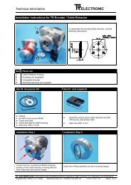
Operating Manual <strong>CE</strong>-<strong>65</strong>-MELEC<strong>TR</strong>ONIC GmbH2.3 AssemblyDrive of the Encoder ShaftSeries <strong>CE</strong> encoders are connected to the drive shaft by an elastic coupling whichtakes up deviations in the axial and radial directions between the encoder and thedrive shaft. This prevents excessive bearing loading. You can order couplings on request.Flange FixingThe centring collar with fit f7 centres the encoder to the shaft. Fixing to the machine isby means of three screws in the flange (Figure 1).Clamping Bracket FixingThe centring collar with fit f7 centres the encoder to the shaft. Fixing of the encoder isby means of two clamping brackets (Figure 2).Figure 1CouplingMachineFigure 2CouplingClamping bracketMachine<strong>TR</strong>-ELEC<strong>TR</strong>ONIC GmbH, Global Quality Management, Eglishalde 6, 78647 Trossingen, Tel. ++49 (0)7425-228-0, Fax ++49 (0)7425-228-33Date: 10.10.1997 <strong>TR</strong> - E<strong>CE</strong> - BA - GB - 0007 - 02 Page 16 of 29
Operating Manual <strong>CE</strong>-<strong>65</strong>-MELEC<strong>TR</strong>ONIC GmbH2.4 Commissioning (Rotary Encoder)2.4.1 Encoder Interface (<strong>INTERBUS</strong>-S)The <strong>CE</strong>-<strong>65</strong>-M absolute encoder with <strong>INTERBUS</strong>-S interface is designed as a remotebus module with 32 I/O data. This makes it easy to integrate in the bus ring in thesame way as a PHOENIX-CONTACT bus terminal. To ensure that the protocol meets<strong>INTERBUS</strong>-S requirements, an SYPI (serial microprocessor interface) is integratedbetween the <strong>CE</strong>-<strong>65</strong>-M absolute encoder and the <strong>INTERBUS</strong>-S. The SYPI is an<strong>INTERBUS</strong>-S protocol chip developed by PHOENIX-CONTACT which carries out thefollowing functions:• BUS interfacing: Directions of reception and transmission• CRC check• Preset• Transfer protocoletc.iNoteAt programming, data is exchanged between the encoder and the master in binaryform.<strong>TR</strong>-ELEC<strong>TR</strong>ONIC GmbH, Global Quality Management, Eglishalde 6, 78647 Trossingen, Tel. ++49 (0)7425-228-0, Fax ++49 (0)7425-228-33Date: 10.10.1997 <strong>TR</strong> - E<strong>CE</strong> - BA - GB - 0007 - 02 Page 17 of 29
Operating Manual <strong>CE</strong>-<strong>65</strong>-MELEC<strong>TR</strong>ONIC GmbH2.4.1.1 Mapping of Encoder Data in the Master (Controller)In the master, the encoder data occupies two-word addresses for IN-data and twowordaddresses for OUT-data. The position of the data in the controller depends onthe physical or logical position of the encoder within the ring. For detailed information,refer to the manual of the master (controller) used. The encoder should be consideredto be a PHOENIX I/O bus terminal and the system processes it as such.Position of the Encoder Data Within the Two-Word AddressesOUT-data relative to the master:Relative word address “1“31 30 29 28 27 26 25 24 23 22 21 20 19 18 17 162 2 2 2 2 2 2 2 2 2 2 2 2 2 2 2MSBLSBOUT-data relative to the master:Relative word address “2“15 14 13 12 11 10 9 8 7 6 5 4 3 2 1 02 2 2 2 2 2 2 2 2 2 2 2 2 2 2 2MSBLSBIN-data relative to the master:Relative word address “1“31 30 29 28 27 26 25 24 23 22 21 20 19 18 17 162 2 2 2 2 2 2 2 2 2 2 2 2 2 2 2MSBLSBIN-data relative to the master:Relative word address “2“15 14 13 12 11 10 9 8 7 6 5 4 3 2 1 02 2 2 2 2 2 2 2 2 2 2 2 2 2 2 2MSBLSB<strong>TR</strong>-ELEC<strong>TR</strong>ONIC GmbH, Global Quality Management, Eglishalde 6, 78647 Trossingen, Tel. ++49 (0)7425-228-0, Fax ++49 (0)7425-228-33Date: 10.10.1997 <strong>TR</strong> - E<strong>CE</strong> - BA - GB - 0007 - 02 Page 18 of 29
Operating Manual <strong>CE</strong>-<strong>65</strong>-MELEC<strong>TR</strong>ONIC GmbHMeaning of the OUT-Data (Data from the Master to the Encoder)Normal Mode:Service bit 2 31 is set to “0“.OUT-data that the master outputs to the encoder does not have any effect and theencoder does not accept it.As a result, in normal mode the encoder only outputs its current position data.Service Mode:Service bit 2 31 is set to “1“.The encoder carries out the master's requested service (e.g. write direction of rotationor read programmed direction of rotation).The system evaluates or ignores the remaining OUT-data 2 23 to 2 0 in dependence onthe requested service.Bit 2 31 : Service bit 0 = Normal mode1 = Service modeBit 2 30 : Read-write bit 0 = Read data1 = Write dataBit 2 29 : Error bit 1 = ErrorBit 2 28 : Reserve Always 0Bit 2 27 to bit 2 24 : ServiceBit 2 23 to bit 2 0 : Data for service if bit 2 30 = 1,otherwise meaninglessMeaning of the IN-Data (Data from the Encoder to the Master)Normal Mode:The encoder outputs the current position data and writes it to bits 2 23 to 2 0 . Bits 2 31 to2 24 are “0“ unless there is an error; in this case, error bit 2 29 = “1“.Service Mode:If the master writes data (read-write bit = 1), the system returns the OUT-data to theIN-data (bits 2 31 to 2 0 ).If the master reads data (read-write bit = 0), bits 2 23 to 2 0 contain the requested dataand bits 2 31 to 2 24 contain the acknowledgement of the requested service.If the system could not carry out the service without errors, the error bit is “0“. It isonly possible to clear a set error bit by carrying out a data check service.<strong>TR</strong>-ELEC<strong>TR</strong>ONIC GmbH, Global Quality Management, Eglishalde 6, 78647 Trossingen, Tel. ++49 (0)7425-228-0, Fax ++49 (0)7425-228-33Date: 10.10.1997 <strong>TR</strong> - E<strong>CE</strong> - BA - GB - 0007 - 02 Page 19 of 29
Operating Manual <strong>CE</strong>-<strong>65</strong>-MELEC<strong>TR</strong>ONIC GmbH3 Parameter Programming (Operation)3.1 Callable ServicesThe system processes all service requests from the host to the encoder by means ofa handshake of the service bit.Handshake of service bit 2 31HostOUT-DATA 2 311 24EncoderIN-DATA 2 31351. The host is in normal mode, service bit 2 31 is 0.The IN-data contains the encoder's actual position.2. The host outputs the data and the service number and sets the service bit to 1.Note:To guarantee data consistency between the commissioning card and the PLC, thedata and the service number must be output first. One PLC cycle later, the servicebit must be set from 0 to 1.With a read service, OUT data 2 23 to 2 0 is meaningless.3. The encoder detects and processes the service request, provides the appropriatedata and reports back to the host system by setting service bit 2 31 . With a readservice, the system returns the OUT data to the IN data.4. The host system detects execution and ends the service request.The system resets service bit 2 31 and switches back to normal mode.5. The encoder also detects the end of the service request and also switches to normalmode by resetting service bit 2 31 . Afterwards, the system continues with theencoder's actual value output.<strong>TR</strong>-ELEC<strong>TR</strong>ONIC GmbH, Global Quality Management, Eglishalde 6, 78647 Trossingen, Tel. ++49 (0)7425-228-0, Fax ++49 (0)7425-228-33Date: 10.10.1997 <strong>TR</strong> - E<strong>CE</strong> - BA - GB - 0007 - 02 Page 20 of 29
Operating Manual <strong>CE</strong>-<strong>65</strong>-MELEC<strong>TR</strong>ONIC GmbH3.1.1 Direction of Counting/Code – Service 01 HexService Request from Master (OUT Data)2 31 to 2 24 2 23 to 2 16 2 15 to 2 8 2 7 to 2 0a) 81 Hex No effect No effect No effect Read datab) C1 Hex 0 or 1 0 or 1 * 0 or 1 Write data(Meaningless) 0 = Binary 0 = CW rising≠ 0 = Gray≠ 0 = CW falling* 0 = Data rising clockwise looking towards the shaft≠ 0 = Data falling clockwise looking towards the shaftService Feedback Message from Encoder (IN Data)2 31 to 2 24 2 23 to 2 0a) 81 Hex 0 or 1 Depending on programmingb) C1 Hex 0 or 1 Depending on programming3.1.2 Measuring Length in Steps – Service 02 HexMeasuring length in steps = (resolution/360 degrees x measuring range in revs) -1Service Request from Master (OUT Data)2 31 to 2 24 2 23 to 2 0a) 82 Hex No effect Read datab) C2 Hex FF FF FF Hex to 10 Hex Write dataService Feedback Message from Encoder (IN Data)2 31 to 2 24 2 23 to 2 0a) 82 Hex FF FF FF Hex to 10 Hex Depending on programmingb) C2 Hex FF FF FF Hex to 10 Hex Depending on programming<strong>TR</strong>-ELEC<strong>TR</strong>ONIC GmbH, Global Quality Management, Eglishalde 6, 78647 Trossingen, Tel. ++49 (0)7425-228-0, Fax ++49 (0)7425-228-33Date: 10.10.1997 <strong>TR</strong> - E<strong>CE</strong> - BA - GB - 0007 - 02 Page 21 of 29
Operating Manual <strong>CE</strong>-<strong>65</strong>-MELEC<strong>TR</strong>ONIC GmbH3.1.3 Measuring Length in Revolutions Numerator – Service 03 HexService Request from Master (OUT Data)2 31 to 2 24 2 23 to 2 0a) 83 Hex No effect Read datab) C3 Hex 00 FF FF Hex to 1 Hex Write dataService Feedback Message from Encoder (IN Data)2 31 to 2 24 2 23 to 2 0a) 83 Hex 00 FF FF Hex to 1 Hex Depending on programmingb) C3 Hex 00 FF FF Hex to 1 Hex Depending on service request3.1.4 Preset Adjustment – Service 06 HexService Request from Master (OUT Data)2 31 to 2 24 2 23 to 2 0C6 Hex Measuring length in steps to 0 Hex Write dataService Feedback Message from Encoder (IN Data)2 31 to 2 24 2 23 to 2 0C6 Hex Measuring length in steps to 0 Hex Depending on service request<strong>TR</strong>-ELEC<strong>TR</strong>ONIC GmbH, Global Quality Management, Eglishalde 6, 78647 Trossingen, Tel. ++49 (0)7425-228-0, Fax ++49 (0)7425-228-33Date: 10.10.1997 <strong>TR</strong> - E<strong>CE</strong> - BA - GB - 0007 - 02 Page 22 of 29
Operating Manual <strong>CE</strong>-<strong>65</strong>-MELEC<strong>TR</strong>ONIC GmbH3.1.5 Data Check – Service 08 HexService Request from Master (OUT Data)2 31 to 2 24 2 23 to 2 088 Hex No effect Read dataService Feedback Message from Encoder (IN Data)2 31 to 2 24 2 23 to 2 088 Hex 2 23 to 2 16 always "0" 2 15 to 2 0 error status3.1.6 Measuring Length in Revolutions Denominator – Service 09 HexService Request from Master (OUT Data)2 31 to 2 24 2 23 to 2 0a) 89 Hex No effect Read datab) C9 Hex 0000 63 Hex to 1 Hex Write dataService Feedback Message from Encoder (IN Data)2 31 to 2 24 2 23 to 2 0a) 89 Hex 0000 63 Hex to 1 Hex Depending on programmingb) C9 Hex 0000 63 Hex to 1 Hex Depending on service request<strong>TR</strong>-ELEC<strong>TR</strong>ONIC GmbH, Global Quality Management, Eglishalde 6, 78647 Trossingen, Tel. ++49 (0)7425-228-0, Fax ++49 (0)7425-228-33Date: 10.10.1997 <strong>TR</strong> - E<strong>CE</strong> - BA - GB - 0007 - 02 Page 23 of 29
Operating Manual <strong>CE</strong>-<strong>65</strong>-MELEC<strong>TR</strong>ONIC GmbH3.1.7 SSI-OUT Data Interface3.1.7.1 SSI Characteristic Values – Service 0D HexService Request from Master (OUT Data)2 31 to 2 24 2 23 to 2 16 2 15 to 2 8 2 7 to 2 0a) 8D Hex No effect No effect No effect Read datab) CD Hex 0 or 1 0 or 1 Number of data bits Write data0 = without repet. 0 = Binary 08 to 20 Hex≠ 0 = with repet. ≠ 0 = Gray Valid starting CW 41/ 97:Entry 1F hex =AK-40 compatibleService Feedback Message from Encoder (IN Data)2 31 to 2 24 2 23 to 2 16 2 15 to 2 8 2 7 to 2 0a) 8D Hex 0 or 1 0 or 1 Number of data bits Depending on08 to 20 Hex programmingb) CD Hex 0 or 1 0 or 1 Number of data bits Depending on0 = without repet. 0 = Binary 08 to 20 Hex service request≠ 0 = with repet. ≠ 0 = Gray<strong>TR</strong>-ELEC<strong>TR</strong>ONIC GmbH, Global Quality Management, Eglishalde 6, 78647 Trossingen, Tel. ++49 (0)7425-228-0, Fax ++49 (0)7425-228-33Date: 10.10.1997 <strong>TR</strong> - E<strong>CE</strong> - BA - GB - 0007 - 02 Page 24 of 29
Operating Manual <strong>CE</strong>-<strong>65</strong>-MELEC<strong>TR</strong>ONIC GmbH3.2 Brief Description of Executable Services3.2.1 Direction of Counting/Code – Service 01 HexHere, you specify the direction of counting and the encoder's code:Value 0 Hex (2 7 to 2 0 ) = encoder position rising clockwise (looking towards shaft)Value ≠ 0 (2 7 to 2 0 ) = encoder position falling clockwise (looking towards shaft)Value 0 Hex (2 15 to 2 8 ) = data output to the <strong>INTERBUS</strong>-S in binary codeValue ≠ 0 (2 15 to 2 8 ) = data output to the <strong>INTERBUS</strong>-S in Gray codeReading and writing are possible.The value range in each case is 0 to FF Hex.3.2.2 Measuring Length in Steps – Service 02 HexHere, you specify the total length in steps:Measuring length in steps = (measuring length /360 degrees x measuring length in revs) -1Reading and writing are possible.The value range is 10 Hex to FF FF FF Hex.3.2.3 Measuring Length in Revolutions (Numerator) – Service 03 Hex,Measuring Length in Revolutions (Denominator) – Service 09 HexHere, you specify the number of revolutions that the encoder carries out within thetotal number of steps.If the number of revolutions is an integer, you should always program the denominatorto the value "1".If the number of revolutions is a decimal number, program the denominator with thedigits after the decimal point.Example:The encoder is intended to resolve 3.5 revolutions.⇒ Revolutions numerator = 35 (service 03 Hex)⇒ Revolutions denominator = 10 (service 09 Hex)If you program a number of revolutions that is not a power of two, the zero point canbe lost if the encoder traverses more than 512 revolutions in a deenergized state.Reading and writing are possible.Value range of numerator: 1 - FF FF HexValue range of denominator: 1 - 63 Hex<strong>TR</strong>-ELEC<strong>TR</strong>ONIC GmbH, Global Quality Management, Eglishalde 6, 78647 Trossingen, Tel. ++49 (0)7425-228-0, Fax ++49 (0)7425-228-33Date: 10.10.1997 <strong>TR</strong> - E<strong>CE</strong> - BA - GB - 0007 - 02 Page 25 of 29
Operating Manual <strong>CE</strong>-<strong>65</strong>-MELEC<strong>TR</strong>ONIC GmbH3.2.4 Preset Adjustment – Service 06 HexUsing preset adjustment, you can adjust the encoder to a specific value via the<strong>INTERBUS</strong>-S ring.Only writing is possible.Value range: 0 to the programmed measuring length in steps (value from service 02 Hex).3.2.5 Data Check – Service 08 HexAfter programming the encoder, you must call the data check service. This callchecks the validity of the programmed data and accepts it. Without this call, the encodercontinues to run with the old parameters until you switch the power off and onagain.Only reading is possible.On 2 0 to 2 15 of the IN data the master receives the error status as the response.Bits 2 16 to 2 23 of the IN data are "0".Bits 2 24 to 2 31 of the IN data feed back the requested service.Error Status2 0 Error reading data2 1 Error writing data2 2 Only reading allowed2 3 Only writing allowed2 4 Always 02 5 Always 02 6 Always 02 7 Unknown command2 8 Always 02 9 Always 02 10 Always 02 11 Always 02 12 Always 02 13 Revolutions numerator = 02 14 Measuring length in steps is too high. Measuring length/360 degrees > encoder resolution same as onencoder's rating plate2 15 Always 0If an error occurs at execution of a service (error bit set in encoder's service feedbackmessage), you can determine the error exactly by carrying out the data check service.<strong>TR</strong>-ELEC<strong>TR</strong>ONIC GmbH, Global Quality Management, Eglishalde 6, 78647 Trossingen, Tel. ++49 (0)7425-228-0, Fax ++49 (0)7425-228-33Date: 10.10.1997 <strong>TR</strong> - E<strong>CE</strong> - BA - GB - 0007 - 02 Page 26 of 29
Operating Manual <strong>CE</strong>-<strong>65</strong>-MELEC<strong>TR</strong>ONIC GmbH3.2.6 SSI-OUT Data InterfaceData TransferAt rest, Data+ and Clock+ are +5V (High). Data transfer starts with the MSB and isinitiated by the first falling clock edge. Data is changed by a positive clock edge. Dependingon the receiver, data is accepted with a rising or a falling edge.When the clock sequence is over, the system keeps the data lines at 0V (Low) for theduration of the mono period, t M . Time t M is set to 20 µs and it determines the lowesttransfer frequency of approximately 50 kHz. The upper limit frequency results fromthe total of all the signal propagation delays and is approximately 1.1 MHz.3.2.6.1 SSI Characteristic Values – Service 0D HexReading and writing are possible.Number of Data BitsUsing this parameter, you can shift data anywhere within the number of clock pulses.The data can be transferred right- or left-justified and with or without leading zeros.You generate leading zeros by generating a higher number of data bits than wouldnormally be necessary for the encoder.Value range: 08 to 20 HexNote (valid starting CW 41 / 97)By programming the number of data bits to 31 (1F hex) the SSI-output format will beset automatic to the AK-40 data format:31 data bits; binary; data bit 32 = Parity oddCodeThe code is a method for forming digital numbers. A code word is a bit pattern thatexpresses a numerical value. The code describes the assignments of code words andtheir values.In the case of multi-step codes, changing the numerical value by 1 results in a newcode word in which several bits are different from the old one. With single-step codes,only one bit changes in the code word in this case.With decadic codes, four bits in each case are grouped together to one decimal digit.The following codes are used:Binary code (multi-step code)Gray code (single-step code)Value range: 00 to FF HexRepetitionUsing the Repetition parameter, you choose whether the data bits in long pulse bundlesare to be repeated every 26 pulses. In this connection, the system automaticallysets the number of data bits to 24.Application: Easy determination of transfer disturbances.Value range: 00 to FF Hex<strong>TR</strong>-ELEC<strong>TR</strong>ONIC GmbH, Global Quality Management, Eglishalde 6, 78647 Trossingen, Tel. ++49 (0)7425-228-0, Fax ++49 (0)7425-228-33Date: 10.10.1997 <strong>TR</strong> - E<strong>CE</strong> - BA - GB - 0007 - 02 Page 27 of 29
Operating Manual <strong>CE</strong>-<strong>65</strong>-MELEC<strong>TR</strong>ONIC GmbH3.3 Example of Programming the Measuring Length in StepsSpecifications:Resolution/360 degreesMeasuring length in revolutions numeratorMeasuring length in revolutions denominator= 3E8 Hex= 0A Hex= 1 HexMeasuring length in steps = Resolution/360 degrees x Measuring length in revolutions numeratorMeasuring length in revolutions denominator= 3E8 x 0A1-1-1= 27 0F HexCarry out the following steps:Service Request from Master (OUT Data)2 31 to 2 24 2 23 to 2 0C2 Hex 00 27 0F Hex Write data/start of handshakeService Feedback Message from Encoder (IN Data)2 31 to 2 24 2 23 to 2 0C2 Hex 00 27 0F Hex Data feedback message/confirm handshakeEnd Service Request from Master (OUT Data)2 31 to 2 24 2 23 to 2 0Bit 2 31 to "0"Rest have no effect/deactivate handshakeService Feedback Message from Encoder (IN Data)2 31 to 2 24 2 23 to 2 0Value "0"Current encoder position/deactivate handshakeFor the system to accept the new Measuring length in steps parameter, a data checkmust be carried out first. If you still have other parameters to program, do not carryout the data check until you have completed programming them.<strong>TR</strong>-ELEC<strong>TR</strong>ONIC GmbH, Global Quality Management, Eglishalde 6, 78647 Trossingen, Tel. ++49 (0)7425-228-0, Fax ++49 (0)7425-228-33Date: 10.10.1997 <strong>TR</strong> - E<strong>CE</strong> - BA - GB - 0007 - 02 Page 28 of 29
Operating Manual <strong>CE</strong>-<strong>65</strong>-MELEC<strong>TR</strong>ONIC GmbH4 Disturbances4.1 Causes of Faults and RemediesDisturbance Cause RemedyEncoder step changesLoose contacts in thewiringCheck all the cabling and wiring used for connecting theencoder.Error reading data(Status bit 2 0 =1)Error writing data(Status bit 2 1 =1)Only reading allowed(Status bit 2 2 =1)Only writing allowed(Status bit 2 3 =1)Unknown command(Status bit 2 7 =1)Revolutions numerator= 0(Status bit 2 13 =1)Measuring length insteps too high(Status bit 2 14 =1)Severe vibrationsElectrical disturbancesExcessive axial andradial loading of theshaft or a samplingdefect.Defective memoryarea in the EEPROMDefective memoryarea in the EEPROMThe system tried tocarry out a write command.The system tried tocarry out a read command.You entered the wrongservice number.You entered a "0"when programmingthe measuring lengthin revolutions numerator(service 03HEX).The revolutions fraction(numerator/denominator)was programmedtoo low."Shock modules“ are used to cushion vibrations shocks andjolts on presses, for example. If the fault keeps occurringdespite these measures, you must replace the encoder.Insulating flanges and couplings and cables with twisted-pairwires for data and supply are useful against electrical disturbances.The cable screens should be grounded on bothends. You should only ground the screen on one end in theswitching cabinet if the machine ground has more disturbancescompared to the switching cabinet ground.Plastic couplings prevent mechanical loading of the shaft. Ifthe fault keeps occurring despite these measures, you mustreplace the encoder.If the error occurs when you try to execute the service again,you must replace the encoder.If the error occurs when you try to execute the service again,you must replace the encoder.Set bit 2 30 (read-write bit) to 0.Set bit 2 30 (read-write bit) to 1.Check the executed service number and correct it.Allowed value range:00 FF FF HEX to 1 HEXThe number of steps per revolution must not exceed theencoder resolution stated on the rating place. Program ahigher setting for the revolutions fraction (numerator/denominator).<strong>TR</strong>-ELEC<strong>TR</strong>ONIC GmbH, Global Quality Management, Eglishalde 6, 78647 Trossingen, Tel. ++49 (0)7425-228-0, Fax ++49 (0)7425-228-33Date: 10.10.1997 <strong>TR</strong> - E<strong>CE</strong> - BA - GB - 0007 - 02 Page 29 of 29