Pocket Transistor Radio Kit 13-0450 - Profe Saul
Pocket Transistor Radio Kit 13-0450 - Profe Saul
Pocket Transistor Radio Kit 13-0450 - Profe Saul

You also want an ePaper? Increase the reach of your titles
YUMPU automatically turns print PDFs into web optimized ePapers that Google loves.
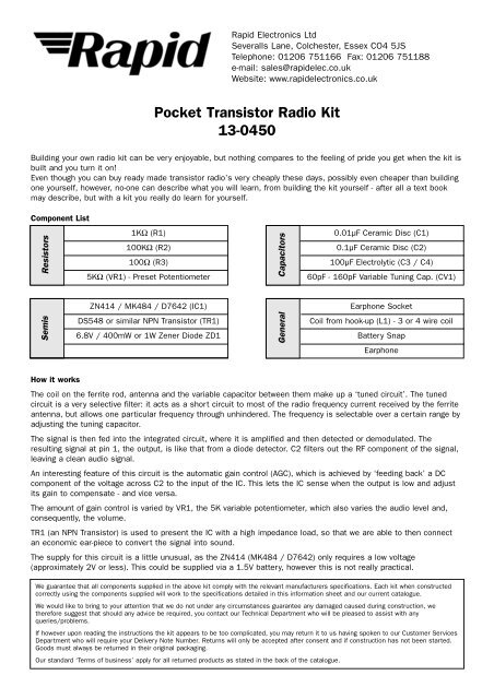
Rapid Electronics LtdSeveralls Lane, Colchester, Essex CO4 5JSTelephone: 01206 751166 Fax: 01206 751188e-mail: sales@rapidelec.co.ukWebsite: www.rapidelectronics.co.uk<strong>Pocket</strong> <strong>Transistor</strong> <strong>Radio</strong> <strong>Kit</strong><strong>13</strong>-<strong>0450</strong>Building your own radio kit can be very enjoyable, but nothing compares to the feeling of pride you get when the kit isbuilt and you turn it on!Even though you can buy ready made transistor radio’s very cheaply these days, possibly even cheaper than buildingone yourself, however, no-one can describe what you will learn, from building the kit yourself - after all a text bookmay describe, but with a kit you really do learn for yourself.Component List1KΩ (R1)0.01µF Ceramic Disc (C1)100KΩ (R2)0.1µF Ceramic Disc (C2)100Ω (R3) 100µF Electrolytic (C3 / C4)5KΩ (VR1) - Preset Potentiometer60pF - 160pF Variable Tuning Cap. (CV1)ResistorsCapacitorsSemisZN414 / MK484 / D7642 (IC1)Earphone SocketDS548 or similar NPN <strong>Transistor</strong> (TR1)Coil from hook-up (L1) - 3 or 4 wire coil6.8V / 400mW or 1W Zener Diode ZD1 Battery SnapGeneralEarphoneHow it worksThe coil on the ferrite rod, antenna and the variable capacitor between them make up a ‘tuned circuit’. The tunedcircuit is a very selective filter: it acts as a short circuit to most of the radio frequency current received by the ferriteantenna, but allows one particular frequency through unhindered. The frequency is selectable over a certain range byadjusting the tuning capacitor.The signal is then fed into the integrated circuit, where it is amplified and then detected or demodulated. Theresulting signal at pin 1, the output, is like that from a diode detector. C2 filters out the RF component of the signal,leaving a clean audio signal.An interesting feature of this circuit is the automatic gain control (AGC), which is achieved by ‘feeding back’ a DCcomponent of the voltage across C2 to the input of the IC. This lets the IC sense when the output is low and adjustits gain to compensate - and vice versa.The amount of gain control is varied by VR1, the 5K variable potentiometer, which also varies the audio level and,consequently, the volume.TR1 (an NPN <strong>Transistor</strong>) is used to present the IC with a high impedance load, so that we are able to then connectan economic ear-piece to convert the signal into sound.The supply for this circuit is a little unusual, as the ZN414 (MK484 / D7642) only requires a low voltage(approximately 2V or less). This could be supplied via a 1.5V battery, however this is not really practical.We guarantee that all components supplied in the above kit comply with the relevant manufacturers specifications. Each kit when constructedcorrectly using the components supplied will work to the specifications detailed in this information sheet and our current catalogue.We would like to bring to your attention that we do not under any circumstances guarantee any damaged caused during construction, wetherefore suggest that should any advice be required, you contact our Technical Department who will be pleased to assist with anyqueries/problems.If however upon reading the instructions the kit appears to be too complicated, you may return it to us having spoken to our Customer ServicesDepartment who will require your Delivery Note Number. Returns will only be accepted after consent and if construction has not been started.Goods must always be returned in their original packaging.Our standard ‘Terms of business’ apply for all returned products as stated in the back of the catalogue.
In order to give the IC the voltage it requires we use a special component called a Zener Diode. The Zener Diode isnormally used as a voltage reference device, as it has quite a stable voltage drop across it. We make use of thisvoltage drop, by connecting the Zener in series with the battery. The voltage drop across the Zener is subtracted fromthe battery voltage leaving us with approximately 2V: just what we want!In order to smooth out any voltage fluctuations, which may occur as the load changes, an electrolyic capacitor isconnected across the normal 2V supply.Definition of resistor colour code100Ω 1KΩ 100KΩBrown Black Brown Brown Black Red Brown Black YellowComponent ViewCoil InformationEarphone socketPCB Mark Coil Lead Colour Coil Lead Colour(3 Wire Coil) (4 Wire Coil)Tuning CapacitorBattery snapB Pink BlackP Red GreenR Not fitted to coil RedG Black or green PinkNote: You may receive either a 3 wire coil or a 4 wire coil(see table above for wiring information)and some of the core coloursmay appear to be faint or dull.Circuit DiagramOptional 'Long wire' AntennaPRGBIC1C1R1R2C2VR1TR1CEBL1- +C3-K-R3AZD1+C4AntennaPinkVR1 5KTrimmerAKEarphoneZD16.8VL1RedBlackGreen2VC160-160pFC1.01uFR2100KZN414*IC<strong>13</strong>1C20.1uFR11KBR3100ΩECTR1DS548+-C3100uF16V+-C4100uF16V-+9V* Please note that the ICmarked on the diagram asZN414, will be an equivalentof the ZN414 (ie MK484 etc.)Assembly TipsWhen soldering components to the PCB, try not to use too much solder as this may cause rounded solder joints.The coil connections must be made via the tip of each lead (the part that is soldered) as the remainder of the lead iscoated with enamel (which will not conduct electricity!).