impact of ethanol on fuel injection pump of diesel engine
impact of ethanol on fuel injection pump of diesel engine
impact of ethanol on fuel injection pump of diesel engine
- No tags were found...

Create successful ePaper yourself
Turn your PDF publications into a flip-book with our unique Google optimized e-Paper software.
ENGINEERING FOR RURAL DEVELOPMENT Jelgava, 26.-27.05.2011.IMPACT OF ETHANOL ON FUEL INJECTION PUMP OF DIESEL ENGINEJuri Olt, Villu Mikita, Risto Ilves, Arne Kuut, Marten MadissooEst<strong>on</strong>ian University <str<strong>on</strong>g>of</str<strong>on</strong>g> Life Sciencesjyri.olt@emu.eeAbstract. In general, it is not purposeful to use <str<strong>on</strong>g>ethanol</str<strong>on</strong>g> as <strong>diesel</strong> <strong>engine</strong> <strong>fuel</strong>, because it causes problems in the<strong>fuel</strong> system. When using <str<strong>on</strong>g>ethanol</str<strong>on</strong>g> in a high-pressure <strong>pump</strong>, <strong>on</strong>e comm<strong>on</strong> problem is the rapid wear or jamming <str<strong>on</strong>g>of</str<strong>on</strong>g>the plunger work surfaces. These problems arise due to the physical and chemical properties <str<strong>on</strong>g>of</str<strong>on</strong>g> <str<strong>on</strong>g>ethanol</str<strong>on</strong>g>. In orderto study the wear-and-tear and work parameters <str<strong>on</strong>g>of</str<strong>on</strong>g> the <strong>pump</strong>, a test was performed with a used high-pressure<strong>pump</strong>. The selecti<strong>on</strong> <str<strong>on</strong>g>of</str<strong>on</strong>g> this <strong>pump</strong> was based <strong>on</strong> the average operati<strong>on</strong> period <str<strong>on</strong>g>of</str<strong>on</strong>g> a tractor, in the case <str<strong>on</strong>g>of</str<strong>on</strong>g>machinery already used in agriculture. This work provides the test data acquired by using bio<str<strong>on</strong>g>ethanol</str<strong>on</strong>g> in a highpressure<strong>pump</strong> and the analysis <str<strong>on</strong>g>of</str<strong>on</strong>g> the results obtained.Keywords: <strong>diesel</strong> <strong>engine</strong>, high-pressure <strong>pump</strong>, bio<str<strong>on</strong>g>ethanol</str<strong>on</strong>g>, work surface.Introducti<strong>on</strong>The research <str<strong>on</strong>g>of</str<strong>on</strong>g> potential uses for alternative <strong>fuel</strong>s is becoming more popular worldwide. Variousbi<str<strong>on</strong>g>of</str<strong>on</strong>g>uels, alcohol <strong>fuel</strong>s, biogas, and plant oils are used as motor <strong>fuel</strong>s in several countries. The problemwith using bi<str<strong>on</strong>g>of</str<strong>on</strong>g>uels c<strong>on</strong>sists in the <str<strong>on</strong>g>impact</str<strong>on</strong>g> <str<strong>on</strong>g>of</str<strong>on</strong>g> their physical-chemical properties <strong>on</strong> the <strong>fuel</strong> supplysystem. One <str<strong>on</strong>g>of</str<strong>on</strong>g> such bi<str<strong>on</strong>g>of</str<strong>on</strong>g>uels is bio<str<strong>on</strong>g>ethanol</str<strong>on</strong>g>.Bio<str<strong>on</strong>g>ethanol</str<strong>on</strong>g> is a prospective and widely used alternative <strong>fuel</strong>, which is used as motor <strong>fuel</strong> in manycountries, such as the USA, Brazil, Germany, and Sweden [1; 2]. Due to its physical-chemicalproperties, bio<str<strong>on</strong>g>ethanol</str<strong>on</strong>g> is mostly used in spark igniti<strong>on</strong> <strong>engine</strong>s. Namely, the auto-igniti<strong>on</strong> temperature<str<strong>on</strong>g>of</str<strong>on</strong>g> <str<strong>on</strong>g>ethanol</str<strong>on</strong>g> is too high to be used in regular compressi<strong>on</strong>-igniti<strong>on</strong> <strong>engine</strong>s. In order to ignite <str<strong>on</strong>g>ethanol</str<strong>on</strong>g> inthe compressi<strong>on</strong>-igniti<strong>on</strong> <strong>engine</strong>, it is necessary to increase the pressure ratio, which results inincreased pressure and temperature in the <strong>engine</strong> cylinder. Besides that the use <str<strong>on</strong>g>of</str<strong>on</strong>g> <str<strong>on</strong>g>ethanol</str<strong>on</strong>g> in <strong>diesel</strong><strong>engine</strong> <strong>fuel</strong>-supply systems is complicated, because the lubricating properties and viscosity <str<strong>on</strong>g>of</str<strong>on</strong>g> <str<strong>on</strong>g>ethanol</str<strong>on</strong>g>are significantly lower than in <strong>diesel</strong> <strong>fuel</strong>. Another problem arises from the water c<strong>on</strong>tent in the <strong>fuel</strong>,which causes corrosi<strong>on</strong> [3]. Due to the aforesaid reas<strong>on</strong>s the precise units <str<strong>on</strong>g>of</str<strong>on</strong>g> the <strong>diesel</strong> <strong>engine</strong> <strong>fuel</strong>supplysystem wear more quickly than when operating <strong>on</strong> regular <strong>fuel</strong>. The precise units may alsooverheat due to increased abrasi<strong>on</strong>, resulting in jamming or breaking <str<strong>on</strong>g>of</str<strong>on</strong>g> the working parts. Therefore,the use <str<strong>on</strong>g>of</str<strong>on</strong>g> <str<strong>on</strong>g>ethanol</str<strong>on</strong>g> in <strong>diesel</strong> <strong>engine</strong> <strong>fuel</strong>-supply systems has not been widely studied. When using<str<strong>on</strong>g>ethanol</str<strong>on</strong>g> in the <strong>diesel</strong> <strong>engine</strong> <strong>fuel</strong>-supply system it is recommended to use a <strong>fuel</strong> injecti<strong>on</strong> <strong>pump</strong> withexternal lubricati<strong>on</strong> or to apply a special layer <str<strong>on</strong>g>of</str<strong>on</strong>g> nanocomposite materials <strong>on</strong> the work surfaces <str<strong>on</strong>g>of</str<strong>on</strong>g> theplungers, in order to increase the durability <str<strong>on</strong>g>of</str<strong>on</strong>g> the operating systems [4]. The aforesaid soluti<strong>on</strong>s havenot been widely used in regular <strong>diesel</strong> <strong>engine</strong> <strong>fuel</strong>-supply systems. This may be due to the high cost <str<strong>on</strong>g>of</str<strong>on</strong>g>the complex systems and special procedures. Without special procedures and external lubricati<strong>on</strong> thework surfaces <str<strong>on</strong>g>of</str<strong>on</strong>g> plunger pairs are processed well enough to allow short-term operati<strong>on</strong> <strong>on</strong> liquids withpoor lubricati<strong>on</strong> qualities. Earlier studies have no reference to the durati<strong>on</strong> <str<strong>on</strong>g>of</str<strong>on</strong>g> plunger pair in theenvir<strong>on</strong>ment which lacks the c<strong>on</strong>diti<strong>on</strong>s required for operati<strong>on</strong>.The article examines the <str<strong>on</strong>g>impact</str<strong>on</strong>g> <str<strong>on</strong>g>of</str<strong>on</strong>g> 94.6 % bio<str<strong>on</strong>g>ethanol</str<strong>on</strong>g> <strong>on</strong> the precise working comp<strong>on</strong>ents <str<strong>on</strong>g>of</str<strong>on</strong>g><strong>diesel</strong> supply equipment. A closer look is given to the technical c<strong>on</strong>diti<strong>on</strong> <str<strong>on</strong>g>of</str<strong>on</strong>g> plunger pairs andinjectors <str<strong>on</strong>g>of</str<strong>on</strong>g> the in-line <strong>fuel</strong>-injecti<strong>on</strong> <strong>pump</strong> before and after operating <strong>on</strong> <str<strong>on</strong>g>ethanol</str<strong>on</strong>g>. The article alsoincludes the study <str<strong>on</strong>g>of</str<strong>on</strong>g> the <str<strong>on</strong>g>impact</str<strong>on</strong>g> <str<strong>on</strong>g>of</str<strong>on</strong>g> <str<strong>on</strong>g>ethanol</str<strong>on</strong>g> <strong>on</strong> the geometry <str<strong>on</strong>g>of</str<strong>on</strong>g> the plunger work surfaces and <strong>on</strong> thechanges in secti<strong>on</strong> capacity <str<strong>on</strong>g>of</str<strong>on</strong>g> the <strong>fuel</strong> injecti<strong>on</strong> <strong>pump</strong>. The aforesaid informati<strong>on</strong> is analysed and anevaluati<strong>on</strong> <str<strong>on</strong>g>of</str<strong>on</strong>g> the <str<strong>on</strong>g>impact</str<strong>on</strong>g> <str<strong>on</strong>g>of</str<strong>on</strong>g> <str<strong>on</strong>g>ethanol</str<strong>on</strong>g> <strong>on</strong> <strong>fuel</strong>-supply equipment is provided. The results are gained bymeans <str<strong>on</strong>g>of</str<strong>on</strong>g> a <strong>fuel</strong>-injecti<strong>on</strong> <strong>pump</strong> test bench, where <strong>fuel</strong>-supply equipment was operated for 100 hoursand the test liquid was 94.6 % bio<str<strong>on</strong>g>ethanol</str<strong>on</strong>g>.Materials and methodsWhen analysing the lubricating properties, <str<strong>on</strong>g>ethanol</str<strong>on</strong>g> with absolute alcohol c<strong>on</strong>tent <str<strong>on</strong>g>of</str<strong>on</strong>g> 94.6 %(surgical spirit) was used as test <strong>fuel</strong> in <strong>fuel</strong>-supply equipment. As <str<strong>on</strong>g>ethanol</str<strong>on</strong>g> is not defined as regular<strong>fuel</strong> in its plain form, its lubricati<strong>on</strong> properties were not analysed. The main parameters whencomparing <str<strong>on</strong>g>ethanol</str<strong>on</strong>g> with regular <strong>fuel</strong> are density and viscosity that enable primary evaluati<strong>on</strong> <str<strong>on</strong>g>of</str<strong>on</strong>g> using254
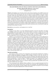
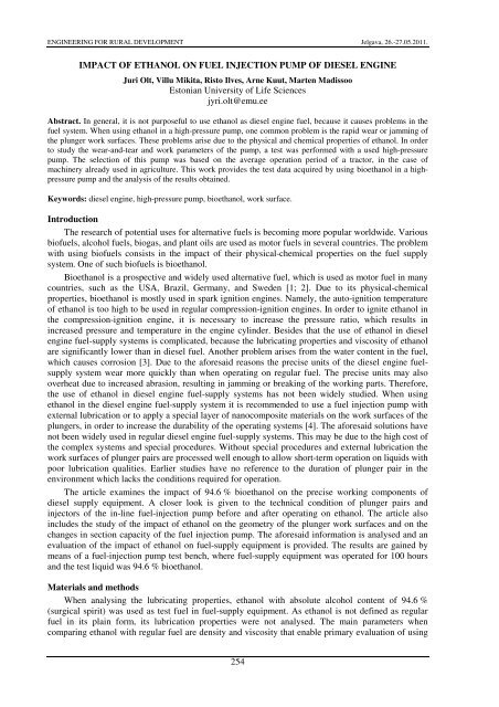
ENGINEERING FOR RURAL DEVELOPMENT Jelgava, 26.-27.05.2011.<str<strong>on</strong>g>ethanol</str<strong>on</strong>g> in the <strong>diesel</strong> <strong>engine</strong> <strong>fuel</strong>-supply system. The main output parameter <str<strong>on</strong>g>of</str<strong>on</strong>g> the <strong>diesel</strong> <strong>engine</strong> <strong>fuel</strong>supplysystem is the <strong>fuel</strong> secti<strong>on</strong> capacity, which characterises the technical c<strong>on</strong>diti<strong>on</strong> <str<strong>on</strong>g>of</str<strong>on</strong>g> the system.The secti<strong>on</strong> capacity is directly associated with the good c<strong>on</strong>diti<strong>on</strong> <str<strong>on</strong>g>of</str<strong>on</strong>g> the subsystems in the <strong>fuel</strong>supplysystem (pre-supply <strong>pump</strong>, <strong>fuel</strong> injecti<strong>on</strong> <strong>pump</strong>, and injectors). Good c<strong>on</strong>diti<strong>on</strong> <str<strong>on</strong>g>of</str<strong>on</strong>g> the <strong>fuel</strong>supplysystem equipment depends <strong>on</strong> the surface quality <str<strong>on</strong>g>of</str<strong>on</strong>g> mutually moving details, which is directlyaffected by corrosi<strong>on</strong> and abrasi<strong>on</strong>. This article focuses mostly <strong>on</strong> the abrasi<strong>on</strong>, which is caused by thelubricating properties <str<strong>on</strong>g>of</str<strong>on</strong>g> the <strong>fuel</strong> and is expressed by the surface the quality <str<strong>on</strong>g>of</str<strong>on</strong>g> moving parts and theirgeometry. The basic moving parts in the <strong>fuel</strong>-supply system include plungers, delivery valve, andinjector nozzles, which require special attenti<strong>on</strong>, as they affect the quality and quantity <str<strong>on</strong>g>of</str<strong>on</strong>g> <strong>fuel</strong>delivery.Test planThe study was performed with regard to the c<strong>on</strong>diti<strong>on</strong> <str<strong>on</strong>g>of</str<strong>on</strong>g> subsystems <str<strong>on</strong>g>of</str<strong>on</strong>g> the <strong>fuel</strong>-supply systemand the wear <str<strong>on</strong>g>of</str<strong>on</strong>g> parts there<str<strong>on</strong>g>of</str<strong>on</strong>g> in the laboratory, based <strong>on</strong> practical tests and by using comm<strong>on</strong> testmethods. The <strong>fuel</strong> injecti<strong>on</strong> <strong>pump</strong> УТН-5A with injectors 6T2 was selected as the <strong>fuel</strong>-supply systemequipment to be tested. The selecti<strong>on</strong> <str<strong>on</strong>g>of</str<strong>on</strong>g> the devices to be tested was based <strong>on</strong> their use in the mostcomm<strong>on</strong> <strong>fuel</strong>-supply systems. The laboratory tasks were divided as follows: 1) measurement <str<strong>on</strong>g>of</str<strong>on</strong>g> initialparameters <str<strong>on</strong>g>of</str<strong>on</strong>g> the parts and adjustment <str<strong>on</strong>g>of</str<strong>on</strong>g> the devices to be tested according to the factoryrequirements; 2) performance <str<strong>on</strong>g>of</str<strong>on</strong>g> durability test; 3) measurement <str<strong>on</strong>g>of</str<strong>on</strong>g> final parameters <str<strong>on</strong>g>of</str<strong>on</strong>g> equipment anddetails. The measurement methods are based <strong>on</strong> the standards specially developed by researchinstituti<strong>on</strong>s, for the devices and parts c<strong>on</strong>sidered in this article in view <str<strong>on</strong>g>of</str<strong>on</strong>g> their particular type <str<strong>on</strong>g>of</str<strong>on</strong>g> wear[5].In order to evaluate the c<strong>on</strong>diti<strong>on</strong> <str<strong>on</strong>g>of</str<strong>on</strong>g> the parts <str<strong>on</strong>g>of</str<strong>on</strong>g> <strong>fuel</strong> injecti<strong>on</strong> <strong>pump</strong>, the compliance <str<strong>on</strong>g>of</str<strong>on</strong>g>operati<strong>on</strong>al parameters <str<strong>on</strong>g>of</str<strong>on</strong>g> plungers and delivery valves (hydraulic density) with the factoryrequirements was measured both before and after the main test. The test stand KI-759 was used formeasuring the hydraulic density <str<strong>on</strong>g>of</str<strong>on</strong>g> plunger pairs. In the course <str<strong>on</strong>g>of</str<strong>on</strong>g> measurement the hydraulic density<str<strong>on</strong>g>of</str<strong>on</strong>g> plunger pairs was evaluated, which characterises the compliance <str<strong>on</strong>g>of</str<strong>on</strong>g> details with the factorystandards up<strong>on</strong> assembly <str<strong>on</strong>g>of</str<strong>on</strong>g> the <strong>pump</strong>. The case was installed in the testing device and filled withspecial stand liquid. When checking, special attenti<strong>on</strong> should be paid to the c<strong>on</strong>diti<strong>on</strong> <str<strong>on</strong>g>of</str<strong>on</strong>g> the bottomcylinder and case fr<strong>on</strong>t surface. Then the plunger was put in place, so that the active guide flute wouldnot coincide with the exhaust outlet. After that the lever was added to the plunger and the stopper wasactivated to measure the time until rapid fall <str<strong>on</strong>g>of</str<strong>on</strong>g> the lever. The test was performed three times for eachplunger pair. The minimum drop time is 30 s for new plunger pairs and 3 s for used plungers. Twomeasurements were performed for checking the delivery valves <strong>on</strong> the stand KI-1086: hydraulicdensity <str<strong>on</strong>g>of</str<strong>on</strong>g> unloading collar; aggregate hydraulic density <str<strong>on</strong>g>of</str<strong>on</strong>g> unloading collar and delivery c<strong>on</strong>e. Inorder to determine the hydraulic density <str<strong>on</strong>g>of</str<strong>on</strong>g> unloading collar the valve with valve seat was placed <strong>on</strong>the stand and then the pressure was elevated up to 0.22 MPa. The measurement <str<strong>on</strong>g>of</str<strong>on</strong>g> time started whenthe pressure dropped to 0.20 MPa, and the time was measured until the pressure in the system droppedto 0.1 MPa. According to the preset values – i.e., minimum 10 s – the unloading collar is c<strong>on</strong>sideredsuitable. For determining the aggregate hydraulic density <str<strong>on</strong>g>of</str<strong>on</strong>g> unloading collar and delivery c<strong>on</strong>e thepressure in the system was brought to 0.82 MPa. The measurement <str<strong>on</strong>g>of</str<strong>on</strong>g> time started when the pressuredropped to 0.80 MPa, and it was measured until the pressure dropped to 0.70 MPa. If the timemeasured is l<strong>on</strong>ger than 30 s, the valve is in order. The stand BOCH EFEP 60H was used for checkingand adjustment <str<strong>on</strong>g>of</str<strong>on</strong>g> the injectors pursuant to the prescribed standards. The injecti<strong>on</strong> pressure <str<strong>on</strong>g>of</str<strong>on</strong>g> theinjectors in questi<strong>on</strong> was adjusted to the pressure <str<strong>on</strong>g>of</str<strong>on</strong>g> 175 bars [6].The methods described above can be used for estimated evaluati<strong>on</strong> <str<strong>on</strong>g>of</str<strong>on</strong>g> the work capacity <str<strong>on</strong>g>of</str<strong>on</strong>g> the<strong>fuel</strong>-supply equipment and its change, but not the exact wear process. In order to provide moreaccurate descripti<strong>on</strong> <str<strong>on</strong>g>of</str<strong>on</strong>g> the changes that take place in the course <str<strong>on</strong>g>of</str<strong>on</strong>g> operati<strong>on</strong>, additi<strong>on</strong>al measurements<str<strong>on</strong>g>of</str<strong>on</strong>g> detail geometry and surface roughness were performed before commencing the main test and aftercompleting the test simultaneously with the measurement <str<strong>on</strong>g>of</str<strong>on</strong>g> hydraulic density <str<strong>on</strong>g>of</str<strong>on</strong>g> <strong>fuel</strong> injecti<strong>on</strong> <strong>pump</strong>parts. The plungers diameter was measured with a micrometer at three different heights towards x axisand each measurement was repeated three times, marked in Figure 1 as: a; b; c. The unloading collardiameter was measured at valves, indicated by letter d in Figure 1. The measurements <str<strong>on</strong>g>of</str<strong>on</strong>g> unloadingcollar geometric circularity <str<strong>on</strong>g>of</str<strong>on</strong>g> plungers and valves was performed by using a device MAHR MMQ-100 (Figure 3), also at three different pre-set heights in order to ensure the repeatability <str<strong>on</strong>g>of</str<strong>on</strong>g> the255
ENGINEERING FOR RURAL DEVELOPMENT Jelgava, 26.-27.05.2011.measurement. Based <strong>on</strong> a comm<strong>on</strong> measurement method the plungers are measured <strong>on</strong>ly at the top(Figure 1) [5]. In additi<strong>on</strong> the surface roughness values R z and R a were measured with MAHR MarSurfMP-1 device from two sides <str<strong>on</strong>g>of</str<strong>on</strong>g> the plunger top. The length <str<strong>on</strong>g>of</str<strong>on</strong>g> the measurement area was 5.6 mm.MAHR MMQ-100 device was used for measuring the circularity <str<strong>on</strong>g>of</str<strong>on</strong>g> the work surface <str<strong>on</strong>g>of</str<strong>on</strong>g> the cylindricalpart <str<strong>on</strong>g>of</str<strong>on</strong>g> the nozzle needle and a micrometer was used for measuring the diameter.Fig. 1. Measurement methods for <strong>fuel</strong> injecti<strong>on</strong> <strong>pump</strong> parts [5]In order to test the <strong>fuel</strong>-supply system equipment the authors decided that the main test should bea short-term operati<strong>on</strong> method, during which the <str<strong>on</strong>g>impact</str<strong>on</strong>g> <str<strong>on</strong>g>of</str<strong>on</strong>g> <strong>fuel</strong> <strong>on</strong> the subsystems and workparameters <str<strong>on</strong>g>of</str<strong>on</strong>g> the <strong>fuel</strong>-supply equipment was evaluated. According to the reference materials thedurati<strong>on</strong> <str<strong>on</strong>g>of</str<strong>on</strong>g> the short-term operati<strong>on</strong> method is 50 hours with interim secti<strong>on</strong> capacity measurementscarried out every 10 hours [5]. The first secti<strong>on</strong> capacity measurement was performed after adjustingthe subsystems <str<strong>on</strong>g>of</str<strong>on</strong>g> the <strong>fuel</strong>-supply equipment to match the factory requirements. The sec<strong>on</strong>dmeasurement was carried out before the main test, i.e., after running the device for <strong>on</strong>e hour, in orderto check whether the setup <str<strong>on</strong>g>of</str<strong>on</strong>g> the <strong>fuel</strong>-supply system equipment remained within the prescribedstandards. The durati<strong>on</strong> <str<strong>on</strong>g>of</str<strong>on</strong>g> our main test was 100 hours with interim measurements performed in every10 hours. The interim measurements were required for checking the stability <str<strong>on</strong>g>of</str<strong>on</strong>g> the work parametersstudied when testing the equipment. A test device was built for performing the test, based <strong>on</strong> a <strong>fuel</strong>injecti<strong>on</strong><strong>pump</strong> test bench SDTA-1 and additi<strong>on</strong>al devices. Using additi<strong>on</strong>al devices <strong>on</strong> the aforesaid<strong>fuel</strong>-injecti<strong>on</strong> <strong>pump</strong> test bench was necessary for several reas<strong>on</strong>s: to prevent the <str<strong>on</strong>g>impact</str<strong>on</strong>g> <str<strong>on</strong>g>of</str<strong>on</strong>g> <strong>fuel</strong>(<str<strong>on</strong>g>ethanol</str<strong>on</strong>g>) <strong>on</strong> the test stand; to reduce the quantity <str<strong>on</strong>g>of</str<strong>on</strong>g> <strong>fuel</strong> used for the test. When preparing the teststand for the main test, it was equipped with the following: <strong>fuel</strong> c<strong>on</strong>tainer; fine filter; cooling device;<strong>fuel</strong> pipes; and thermometer (Figure 2).Fig. 2. Scheme <str<strong>on</strong>g>of</str<strong>on</strong>g> test principle: 1– stand; 2 – <strong>fuel</strong> injecti<strong>on</strong> <strong>pump</strong>; 3 – <strong>fuel</strong> pre-supply <strong>pump</strong>;4 – injector; 5 – <strong>fuel</strong> c<strong>on</strong>tainer; 6 – cooling system; 7 – <strong>fuel</strong> injecti<strong>on</strong> pipes; 8 – <strong>fuel</strong> pre-supply pipes;9 – thermometer; 10 – fine filterThe stability <str<strong>on</strong>g>of</str<strong>on</strong>g> the operating temperature <str<strong>on</strong>g>of</str<strong>on</strong>g> the <strong>fuel</strong> injecti<strong>on</strong> <strong>pump</strong> t fp = 37 °C was ensured by anadditi<strong>on</strong>al cooling device installed <strong>on</strong> the stand. The rotati<strong>on</strong>al speed <str<strong>on</strong>g>of</str<strong>on</strong>g> the test stand when performing256
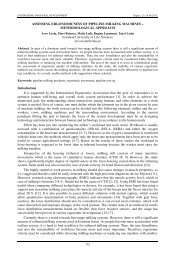
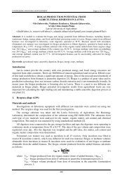
ENGINEERING FOR RURAL DEVELOPMENT Jelgava, 26.-27.05.2011.the tests and measurements was n fp =800 rpm, based <strong>on</strong> the rotati<strong>on</strong>al speed <str<strong>on</strong>g>of</str<strong>on</strong>g> the test <strong>engine</strong> equippedwith a <strong>fuel</strong> injecti<strong>on</strong> <strong>pump</strong> and operating at rated power n e =1600 rpm. The <strong>fuel</strong> secti<strong>on</strong> capacity waschecked separately for each secti<strong>on</strong> and the durati<strong>on</strong> <str<strong>on</strong>g>of</str<strong>on</strong>g> <strong>on</strong>e measurement was n c =800 operating cycles.The <strong>fuel</strong> quantity was measured in cm 3 .Results and discussi<strong>on</strong>The technical c<strong>on</strong>diti<strong>on</strong> <str<strong>on</strong>g>of</str<strong>on</strong>g> the <strong>fuel</strong>-supply equipment can be evaluated by means <str<strong>on</strong>g>of</str<strong>on</strong>g> the secti<strong>on</strong>capacity. If the capacity complies with the values indicated in the technical specificati<strong>on</strong>s, the <strong>engine</strong>receives the required amount <str<strong>on</strong>g>of</str<strong>on</strong>g> <strong>fuel</strong> in every operating mode, provided that the regulator <str<strong>on</strong>g>of</str<strong>on</strong>g> the <strong>fuel</strong>injecti<strong>on</strong> <strong>pump</strong> and other subsystems are in good order. The results <str<strong>on</strong>g>of</str<strong>on</strong>g> secti<strong>on</strong> capacity measurementcarried out in the course <str<strong>on</strong>g>of</str<strong>on</strong>g> the test are shown in Figure 3.The test results reveal that when using the stand liquid and <str<strong>on</strong>g>ethanol</str<strong>on</strong>g> in the <strong>fuel</strong> injecti<strong>on</strong> <strong>pump</strong>there was no significant change in the secti<strong>on</strong> capacity, irrespective <str<strong>on</strong>g>of</str<strong>on</strong>g> the differences in the densityand viscosity <str<strong>on</strong>g>of</str<strong>on</strong>g> <strong>diesel</strong> <strong>fuel</strong> and <str<strong>on</strong>g>ethanol</str<strong>on</strong>g>. This leads to a c<strong>on</strong>clusi<strong>on</strong> that the <strong>fuel</strong> injecti<strong>on</strong> <strong>pump</strong> doesnot need a separate secti<strong>on</strong> capacity adjustment when using <str<strong>on</strong>g>ethanol</str<strong>on</strong>g>. In order to compensate thedifference in the calorific value <str<strong>on</strong>g>of</str<strong>on</strong>g> the <strong>fuel</strong> compared to using <strong>diesel</strong> <strong>fuel</strong> in the <strong>engine</strong>, it is possible toincrease the secti<strong>on</strong> capacity. After the first ten-hour test cycle the capacity <str<strong>on</strong>g>of</str<strong>on</strong>g> the first and fourthsecti<strong>on</strong> was reduced by 6 cm 3 . The reducti<strong>on</strong> <str<strong>on</strong>g>of</str<strong>on</strong>g> the secti<strong>on</strong> capacity was caused by the shifting thatoccurred between the case and c<strong>on</strong>trol rack when running in the <strong>fuel</strong> injecti<strong>on</strong> <strong>pump</strong>. No significantreducti<strong>on</strong> <str<strong>on</strong>g>of</str<strong>on</strong>g> the secti<strong>on</strong> capacity was observed in the course <str<strong>on</strong>g>of</str<strong>on</strong>g> further test cycles, as seen in Figure 3.By the end <str<strong>on</strong>g>of</str<strong>on</strong>g> the sec<strong>on</strong>d test cycle (after 10 hours <str<strong>on</strong>g>of</str<strong>on</strong>g> operati<strong>on</strong>) the capacity <str<strong>on</strong>g>of</str<strong>on</strong>g> the sec<strong>on</strong>d secti<strong>on</strong>increased by 2 cm 3 . During the fourth operating cycle (after 30 hours <str<strong>on</strong>g>of</str<strong>on</strong>g> operati<strong>on</strong>) the capacities <str<strong>on</strong>g>of</str<strong>on</strong>g>the third and the first secti<strong>on</strong> were also increased. Based <strong>on</strong> the final measurements <str<strong>on</strong>g>of</str<strong>on</strong>g> injecti<strong>on</strong>pressures we may c<strong>on</strong>clude that the increase in capacity is caused by the reducti<strong>on</strong> <str<strong>on</strong>g>of</str<strong>on</strong>g> the injecti<strong>on</strong>pressure: I secti<strong>on</strong> – 28 bar; II secti<strong>on</strong> – 30 bar; III secti<strong>on</strong> – 40 bar; IV secti<strong>on</strong> – 20 bar.3·min-1Secti<strong>on</strong> capacity, cmI secti<strong>on</strong>II secti<strong>on</strong>III secti<strong>on</strong>IV secti<strong>on</strong>Working hours, hFig. 3. Secti<strong>on</strong> capacity <str<strong>on</strong>g>of</str<strong>on</strong>g> injecti<strong>on</strong> <strong>pump</strong> depending <strong>on</strong> test timeThe injecti<strong>on</strong> pressure in the fourth secti<strong>on</strong> was reduced the least, which is also characterised bythe stability <str<strong>on</strong>g>of</str<strong>on</strong>g> the capacity throughout the test. The secti<strong>on</strong> pressures in other secti<strong>on</strong>s were reducedmore than in the secti<strong>on</strong> four, but they remained within the standard limit and did not involvesignificant increase in capacity.Reducti<strong>on</strong> <str<strong>on</strong>g>of</str<strong>on</strong>g> injecti<strong>on</strong> pressures was caused by the wear generated when running in the worksurfaces <str<strong>on</strong>g>of</str<strong>on</strong>g> the nozzle needles. The measurement <str<strong>on</strong>g>of</str<strong>on</strong>g> needle geometric circularity revealed the highestdeflecti<strong>on</strong> in case <str<strong>on</strong>g>of</str<strong>on</strong>g> the nozzle needle in the third secti<strong>on</strong> (see Figure 4). It follows that the reducti<strong>on</strong><str<strong>on</strong>g>of</str<strong>on</strong>g> the injecti<strong>on</strong> pressure in the third secti<strong>on</strong> was due to the increased deflecti<strong>on</strong> <str<strong>on</strong>g>of</str<strong>on</strong>g> shape, incomparis<strong>on</strong> with other secti<strong>on</strong>s. According to a general tendency the shape deflecti<strong>on</strong>s were reducedin the course <str<strong>on</strong>g>of</str<strong>on</strong>g> the test. But in case <str<strong>on</strong>g>of</str<strong>on</strong>g> the injector in the third secti<strong>on</strong> the deflecti<strong>on</strong> increased instead.257
ENGINEERING FOR RURAL DEVELOPMENT Jelgava, 26.-27.05.2011.Irrespective <str<strong>on</strong>g>of</str<strong>on</strong>g> that we may c<strong>on</strong>clude that using <str<strong>on</strong>g>ethanol</str<strong>on</strong>g> does not cause ultrafast wear <str<strong>on</strong>g>of</str<strong>on</strong>g> the preciseunits <str<strong>on</strong>g>of</str<strong>on</strong>g> injectors.Fig. 4. Measurement results <str<strong>on</strong>g>of</str<strong>on</strong>g> geometric circularity <str<strong>on</strong>g>of</str<strong>on</strong>g> subsystem partsThe results <str<strong>on</strong>g>of</str<strong>on</strong>g> measuring the delivery valve retracti<strong>on</strong> collar geometric circularity revealed thereducti<strong>on</strong> <str<strong>on</strong>g>of</str<strong>on</strong>g> mean deflecti<strong>on</strong> in all secti<strong>on</strong>s. The reducti<strong>on</strong> <str<strong>on</strong>g>of</str<strong>on</strong>g> deflecti<strong>on</strong>s was caused by running in thedetails. We may c<strong>on</strong>clude that the operati<strong>on</strong> <str<strong>on</strong>g>of</str<strong>on</strong>g> the valves in <str<strong>on</strong>g>ethanol</str<strong>on</strong>g> envir<strong>on</strong>ment during 100 workhours does not cause significant wear that would lead to major changes in the capacity <str<strong>on</strong>g>of</str<strong>on</strong>g> the <strong>fuel</strong>supplyequipment. The same can be said to describe the wear <str<strong>on</strong>g>of</str<strong>on</strong>g> the plunger pairs. The greatest changein deflecti<strong>on</strong>, 1.667 µm, was found in the fourth plunger (Figure 4). The results gained from themeasurement <str<strong>on</strong>g>of</str<strong>on</strong>g> the hydraulic density <str<strong>on</strong>g>of</str<strong>on</strong>g> plunger pairs did not differ from the initial measurements,and the results corresp<strong>on</strong>ded to the factory requirements. Under the microscope <strong>on</strong>e can see barelynoticeable scratches <strong>on</strong> the surface <str<strong>on</strong>g>of</str<strong>on</strong>g> the plunger. More visible scratches <str<strong>on</strong>g>of</str<strong>on</strong>g> the work surface,however, are seen <strong>on</strong> the delivery valve retracti<strong>on</strong> collars (Figure 5), which, according to themeasurement results, did not change the hydraulic density according to the factory requirements.a b cdFig. 5. Work surface <str<strong>on</strong>g>of</str<strong>on</strong>g> subsystem: a – unloading collar before testing; b – unloading collar aftertesting; c – <strong>pump</strong> plunger before testing; d – <strong>pump</strong> plunger after testing.258
ENGINEERING FOR RURAL DEVELOPMENT Jelgava, 26.-27.05.2011.As a result <str<strong>on</strong>g>of</str<strong>on</strong>g> all measurements we determined average surface roughness <str<strong>on</strong>g>of</str<strong>on</strong>g> the plungersR a =0.035 µm and the average distance between the highest and lowest point <str<strong>on</strong>g>of</str<strong>on</strong>g> surface irregularitiesR z =0.6 µm. The average difference in the plunger diameters, measured with micrometre before andafter the test, was no more than 0.003 µm and the average difference in the nozzle needle diameterswas no more than 0.0005 µm (calculated). The micrometer error limit is 0.0005 µm. The <strong>on</strong>lyexcepti<strong>on</strong> was the third secti<strong>on</strong> injector, the nozzle needle diameter <str<strong>on</strong>g>of</str<strong>on</strong>g> which had reduced to 0.001 µmand hence caused the most significant reducti<strong>on</strong> in the injecti<strong>on</strong> pressure.The main problem when using <str<strong>on</strong>g>ethanol</str<strong>on</strong>g> in the <strong>fuel</strong>-injecti<strong>on</strong> <strong>pump</strong> was the possible c<strong>on</strong>tact <str<strong>on</strong>g>of</str<strong>on</strong>g><str<strong>on</strong>g>ethanol</str<strong>on</strong>g> with lubricant oil. The problem c<strong>on</strong>sists in n<strong>on</strong>-solubility <str<strong>on</strong>g>of</str<strong>on</strong>g> <str<strong>on</strong>g>ethanol</str<strong>on</strong>g> and oil, which may causeserious issues in centrally oiled <strong>engine</strong>s with this type <str<strong>on</strong>g>of</str<strong>on</strong>g> <strong>fuel</strong> injecti<strong>on</strong> <strong>pump</strong>s. The aforesaid problemshould not occur in case <str<strong>on</strong>g>of</str<strong>on</strong>g> plunger pairs with additi<strong>on</strong>al reflux flute, but this was not the mainobjective <str<strong>on</strong>g>of</str<strong>on</strong>g> this study. Another problem arises from corrosi<strong>on</strong> generated during the storage <str<strong>on</strong>g>of</str<strong>on</strong>g> the<strong>pump</strong>, as it causes damage to the work surfaces <str<strong>on</strong>g>of</str<strong>on</strong>g> the moving parts.C<strong>on</strong>clusi<strong>on</strong>sThe aim <str<strong>on</strong>g>of</str<strong>on</strong>g> the study discussed in this article was to determine the <str<strong>on</strong>g>impact</str<strong>on</strong>g> <str<strong>on</strong>g>of</str<strong>on</strong>g> <str<strong>on</strong>g>ethanol</str<strong>on</strong>g> <strong>on</strong> the outputparameters <str<strong>on</strong>g>of</str<strong>on</strong>g> the <strong>diesel</strong> <strong>engine</strong> <strong>fuel</strong> injecti<strong>on</strong> <strong>pump</strong> УТН-5A, and the details <str<strong>on</strong>g>of</str<strong>on</strong>g> subsystem <str<strong>on</strong>g>of</str<strong>on</strong>g> <strong>fuel</strong>supplyequipment. The tests revealed that:1. The <strong>pump</strong> secti<strong>on</strong> capacity with the same work parameters <str<strong>on</strong>g>of</str<strong>on</strong>g> the <strong>fuel</strong>-supply equipment shows nosignificant change when using <str<strong>on</strong>g>ethanol</str<strong>on</strong>g> in comparis<strong>on</strong> to <strong>diesel</strong> <strong>fuel</strong>;2. When using <str<strong>on</strong>g>ethanol</str<strong>on</strong>g>, the work surfaces did not have any significant damage that could affect thecapacity and reliability <str<strong>on</strong>g>of</str<strong>on</strong>g> the <strong>fuel</strong>-supply equipment;3. The geometric circularity <str<strong>on</strong>g>of</str<strong>on</strong>g> the measured work parts were generally improved. This leads to thec<strong>on</strong>clusi<strong>on</strong> that <str<strong>on</strong>g>ethanol</str<strong>on</strong>g> envir<strong>on</strong>ment is suitable for running in the details indicated in the study;4. Due to its low viscosity, <str<strong>on</strong>g>ethanol</str<strong>on</strong>g> comes into c<strong>on</strong>tact with lubricant through plunger pairs whenusing this type <str<strong>on</strong>g>of</str<strong>on</strong>g> <strong>fuel</strong> injecti<strong>on</strong> <strong>pump</strong>s;5. The risk <str<strong>on</strong>g>of</str<strong>on</strong>g> corrosi<strong>on</strong> <str<strong>on</strong>g>of</str<strong>on</strong>g> the work surfaces is higher in case <str<strong>on</strong>g>of</str<strong>on</strong>g> l<strong>on</strong>g-term storage <str<strong>on</strong>g>of</str<strong>on</strong>g> the <strong>fuel</strong>-supplyequipment that has been used with <str<strong>on</strong>g>ethanol</str<strong>on</strong>g> than in case <str<strong>on</strong>g>of</str<strong>on</strong>g> equipment operating <strong>on</strong> <strong>diesel</strong> <strong>fuel</strong>.Based <strong>on</strong> the previous results and analyses we may c<strong>on</strong>clude that using <str<strong>on</strong>g>ethanol</str<strong>on</strong>g> in <strong>fuel</strong>-supplyequipment does not cause jamming <str<strong>on</strong>g>of</str<strong>on</strong>g> precise units and c<strong>on</strong>sequent subsystem failure. But these testsdo not allow accurate evaluati<strong>on</strong> <str<strong>on</strong>g>of</str<strong>on</strong>g> the maximum durati<strong>on</strong> <str<strong>on</strong>g>of</str<strong>on</strong>g> operati<strong>on</strong> <str<strong>on</strong>g>of</str<strong>on</strong>g> the <strong>fuel</strong>-supply equipment.The authors recommend using additives that improve lubricati<strong>on</strong>. In the given field further studiesshall be carried out with regard to the <strong>diesel</strong> <strong>engine</strong> <strong>fuel</strong>-supply equipment with a different structure,by using <str<strong>on</strong>g>ethanol</str<strong>on</strong>g> mixtures with various alcohol c<strong>on</strong>tent based <strong>on</strong> renewable raw materials.References1. Harndorf H., Schuemann U., Wichmann V., Fink C. Motorprozessverhalten und Abgasemissi<strong>on</strong>enalternativer Kraftst<str<strong>on</strong>g>of</str<strong>on</strong>g>fe im Vergleich mit Dieselkraftst<str<strong>on</strong>g>of</str<strong>on</strong>g>f, MTZ 7-8/2008, 69 Jahrgang, 2008. pp.640-646.2. Steinbach N., Harndorf H., Weberbauer F., Thiel M. Motorisches Potential v<strong>on</strong> synthetischenDieselkraftst<str<strong>on</strong>g>of</str<strong>on</strong>g>fen, MTZ 02/2006, 67 Jahrgang, 2006. pp. 96-102.3. Govindarajan K. Alcohol as an Automotive Fuel, 2008. [<strong>on</strong>line] [04.03.2011]. Available at:http://www.cheresources.com/energy_future/<str<strong>on</strong>g>ethanol</str<strong>on</strong>g>_transportati<strong>on</strong>_<strong>fuel</strong>.shtml.4. Ma X.Q., DeCarmine., Xiao T.D. Plasma Spray High Lubricity Nanocomposite Coatings.Thermal Spray 2004, Advances in Tehnology and Applicati<strong>on</strong>.5. Baširov R., Kislov V., Pavlov V., Popov V. Reliability <str<strong>on</strong>g>of</str<strong>on</strong>g> Fuel Injecti<strong>on</strong> Equipment Tractor andCombine Diesels. Engineering. 1978. 184 p. (in Russian)6. Kirsi T. Machinery Maintenance, Diagnosis and Repair. Tallinn: Valgus, 1991. 400 p. (inEst<strong>on</strong>ian)259