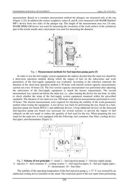
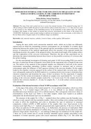
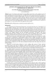
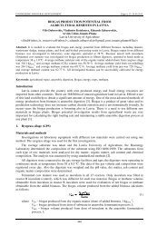
ENGINEERING FOR RURAL DEVELOPMENT Jelgava, 26.-27.05.2011.<str<strong>on</strong>g>ethanol</str<strong>on</strong>g> in the <strong>diesel</strong> <strong>engine</strong> <strong>fuel</strong>-supply system. The main output parameter <str<strong>on</strong>g>of</str<strong>on</strong>g> the <strong>diesel</strong> <strong>engine</strong> <strong>fuel</strong>supplysystem is the <strong>fuel</strong> secti<strong>on</strong> capacity, which characterises the technical c<strong>on</strong>diti<strong>on</strong> <str<strong>on</strong>g>of</str<strong>on</strong>g> the system.The secti<strong>on</strong> capacity is directly associated with the good c<strong>on</strong>diti<strong>on</strong> <str<strong>on</strong>g>of</str<strong>on</strong>g> the subsystems in the <strong>fuel</strong>supplysystem (pre-supply <strong>pump</strong>, <strong>fuel</strong> injecti<strong>on</strong> <strong>pump</strong>, and injectors). Good c<strong>on</strong>diti<strong>on</strong> <str<strong>on</strong>g>of</str<strong>on</strong>g> the <strong>fuel</strong>supplysystem equipment depends <strong>on</strong> the surface quality <str<strong>on</strong>g>of</str<strong>on</strong>g> mutually moving details, which is directlyaffected by corrosi<strong>on</strong> and abrasi<strong>on</strong>. This article focuses mostly <strong>on</strong> the abrasi<strong>on</strong>, which is caused by thelubricating properties <str<strong>on</strong>g>of</str<strong>on</strong>g> the <strong>fuel</strong> and is expressed by the surface the quality <str<strong>on</strong>g>of</str<strong>on</strong>g> moving parts and theirgeometry. The basic moving parts in the <strong>fuel</strong>-supply system include plungers, delivery valve, andinjector nozzles, which require special attenti<strong>on</strong>, as they affect the quality and quantity <str<strong>on</strong>g>of</str<strong>on</strong>g> <strong>fuel</strong>delivery.Test planThe study was performed with regard to the c<strong>on</strong>diti<strong>on</strong> <str<strong>on</strong>g>of</str<strong>on</strong>g> subsystems <str<strong>on</strong>g>of</str<strong>on</strong>g> the <strong>fuel</strong>-supply systemand the wear <str<strong>on</strong>g>of</str<strong>on</strong>g> parts there<str<strong>on</strong>g>of</str<strong>on</strong>g> in the laboratory, based <strong>on</strong> practical tests and by using comm<strong>on</strong> testmethods. The <strong>fuel</strong> injecti<strong>on</strong> <strong>pump</strong> УТН-5A with injectors 6T2 was selected as the <strong>fuel</strong>-supply systemequipment to be tested. The selecti<strong>on</strong> <str<strong>on</strong>g>of</str<strong>on</strong>g> the devices to be tested was based <strong>on</strong> their use in the mostcomm<strong>on</strong> <strong>fuel</strong>-supply systems. The laboratory tasks were divided as follows: 1) measurement <str<strong>on</strong>g>of</str<strong>on</strong>g> initialparameters <str<strong>on</strong>g>of</str<strong>on</strong>g> the parts and adjustment <str<strong>on</strong>g>of</str<strong>on</strong>g> the devices to be tested according to the factoryrequirements; 2) performance <str<strong>on</strong>g>of</str<strong>on</strong>g> durability test; 3) measurement <str<strong>on</strong>g>of</str<strong>on</strong>g> final parameters <str<strong>on</strong>g>of</str<strong>on</strong>g> equipment anddetails. The measurement methods are based <strong>on</strong> the standards specially developed by researchinstituti<strong>on</strong>s, for the devices and parts c<strong>on</strong>sidered in this article in view <str<strong>on</strong>g>of</str<strong>on</strong>g> their particular type <str<strong>on</strong>g>of</str<strong>on</strong>g> wear[5].In order to evaluate the c<strong>on</strong>diti<strong>on</strong> <str<strong>on</strong>g>of</str<strong>on</strong>g> the parts <str<strong>on</strong>g>of</str<strong>on</strong>g> <strong>fuel</strong> injecti<strong>on</strong> <strong>pump</strong>, the compliance <str<strong>on</strong>g>of</str<strong>on</strong>g>operati<strong>on</strong>al parameters <str<strong>on</strong>g>of</str<strong>on</strong>g> plungers and delivery valves (hydraulic density) with the factoryrequirements was measured both before and after the main test. The test stand KI-759 was used formeasuring the hydraulic density <str<strong>on</strong>g>of</str<strong>on</strong>g> plunger pairs. In the course <str<strong>on</strong>g>of</str<strong>on</strong>g> measurement the hydraulic density<str<strong>on</strong>g>of</str<strong>on</strong>g> plunger pairs was evaluated, which characterises the compliance <str<strong>on</strong>g>of</str<strong>on</strong>g> details with the factorystandards up<strong>on</strong> assembly <str<strong>on</strong>g>of</str<strong>on</strong>g> the <strong>pump</strong>. The case was installed in the testing device and filled withspecial stand liquid. When checking, special attenti<strong>on</strong> should be paid to the c<strong>on</strong>diti<strong>on</strong> <str<strong>on</strong>g>of</str<strong>on</strong>g> the bottomcylinder and case fr<strong>on</strong>t surface. Then the plunger was put in place, so that the active guide flute wouldnot coincide with the exhaust outlet. After that the lever was added to the plunger and the stopper wasactivated to measure the time until rapid fall <str<strong>on</strong>g>of</str<strong>on</strong>g> the lever. The test was performed three times for eachplunger pair. The minimum drop time is 30 s for new plunger pairs and 3 s for used plungers. Twomeasurements were performed for checking the delivery valves <strong>on</strong> the stand KI-1086: hydraulicdensity <str<strong>on</strong>g>of</str<strong>on</strong>g> unloading collar; aggregate hydraulic density <str<strong>on</strong>g>of</str<strong>on</strong>g> unloading collar and delivery c<strong>on</strong>e. Inorder to determine the hydraulic density <str<strong>on</strong>g>of</str<strong>on</strong>g> unloading collar the valve with valve seat was placed <strong>on</strong>the stand and then the pressure was elevated up to 0.22 MPa. The measurement <str<strong>on</strong>g>of</str<strong>on</strong>g> time started whenthe pressure dropped to 0.20 MPa, and the time was measured until the pressure in the system droppedto 0.1 MPa. According to the preset values – i.e., minimum 10 s – the unloading collar is c<strong>on</strong>sideredsuitable. For determining the aggregate hydraulic density <str<strong>on</strong>g>of</str<strong>on</strong>g> unloading collar and delivery c<strong>on</strong>e thepressure in the system was brought to 0.82 MPa. The measurement <str<strong>on</strong>g>of</str<strong>on</strong>g> time started when the pressuredropped to 0.80 MPa, and it was measured until the pressure dropped to 0.70 MPa. If the timemeasured is l<strong>on</strong>ger than 30 s, the valve is in order. The stand BOCH EFEP 60H was used for checkingand adjustment <str<strong>on</strong>g>of</str<strong>on</strong>g> the injectors pursuant to the prescribed standards. The injecti<strong>on</strong> pressure <str<strong>on</strong>g>of</str<strong>on</strong>g> theinjectors in questi<strong>on</strong> was adjusted to the pressure <str<strong>on</strong>g>of</str<strong>on</strong>g> 175 bars [6].The methods described above can be used for estimated evaluati<strong>on</strong> <str<strong>on</strong>g>of</str<strong>on</strong>g> the work capacity <str<strong>on</strong>g>of</str<strong>on</strong>g> the<strong>fuel</strong>-supply equipment and its change, but not the exact wear process. In order to provide moreaccurate descripti<strong>on</strong> <str<strong>on</strong>g>of</str<strong>on</strong>g> the changes that take place in the course <str<strong>on</strong>g>of</str<strong>on</strong>g> operati<strong>on</strong>, additi<strong>on</strong>al measurements<str<strong>on</strong>g>of</str<strong>on</strong>g> detail geometry and surface roughness were performed before commencing the main test and aftercompleting the test simultaneously with the measurement <str<strong>on</strong>g>of</str<strong>on</strong>g> hydraulic density <str<strong>on</strong>g>of</str<strong>on</strong>g> <strong>fuel</strong> injecti<strong>on</strong> <strong>pump</strong>parts. The plungers diameter was measured with a micrometer at three different heights towards x axisand each measurement was repeated three times, marked in Figure 1 as: a; b; c. The unloading collardiameter was measured at valves, indicated by letter d in Figure 1. The measurements <str<strong>on</strong>g>of</str<strong>on</strong>g> unloadingcollar geometric circularity <str<strong>on</strong>g>of</str<strong>on</strong>g> plungers and valves was performed by using a device MAHR MMQ-100 (Figure 3), also at three different pre-set heights in order to ensure the repeatability <str<strong>on</strong>g>of</str<strong>on</strong>g> the255
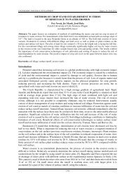
ENGINEERING FOR RURAL DEVELOPMENT Jelgava, 26.-27.05.2011.measurement. Based <strong>on</strong> a comm<strong>on</strong> measurement method the plungers are measured <strong>on</strong>ly at the top(Figure 1) [5]. In additi<strong>on</strong> the surface roughness values R z and R a were measured with MAHR MarSurfMP-1 device from two sides <str<strong>on</strong>g>of</str<strong>on</strong>g> the plunger top. The length <str<strong>on</strong>g>of</str<strong>on</strong>g> the measurement area was 5.6 mm.MAHR MMQ-100 device was used for measuring the circularity <str<strong>on</strong>g>of</str<strong>on</strong>g> the work surface <str<strong>on</strong>g>of</str<strong>on</strong>g> the cylindricalpart <str<strong>on</strong>g>of</str<strong>on</strong>g> the nozzle needle and a micrometer was used for measuring the diameter.Fig. 1. Measurement methods for <strong>fuel</strong> injecti<strong>on</strong> <strong>pump</strong> parts [5]In order to test the <strong>fuel</strong>-supply system equipment the authors decided that the main test should bea short-term operati<strong>on</strong> method, during which the <str<strong>on</strong>g>impact</str<strong>on</strong>g> <str<strong>on</strong>g>of</str<strong>on</strong>g> <strong>fuel</strong> <strong>on</strong> the subsystems and workparameters <str<strong>on</strong>g>of</str<strong>on</strong>g> the <strong>fuel</strong>-supply equipment was evaluated. According to the reference materials thedurati<strong>on</strong> <str<strong>on</strong>g>of</str<strong>on</strong>g> the short-term operati<strong>on</strong> method is 50 hours with interim secti<strong>on</strong> capacity measurementscarried out every 10 hours [5]. The first secti<strong>on</strong> capacity measurement was performed after adjustingthe subsystems <str<strong>on</strong>g>of</str<strong>on</strong>g> the <strong>fuel</strong>-supply equipment to match the factory requirements. The sec<strong>on</strong>dmeasurement was carried out before the main test, i.e., after running the device for <strong>on</strong>e hour, in orderto check whether the setup <str<strong>on</strong>g>of</str<strong>on</strong>g> the <strong>fuel</strong>-supply system equipment remained within the prescribedstandards. The durati<strong>on</strong> <str<strong>on</strong>g>of</str<strong>on</strong>g> our main test was 100 hours with interim measurements performed in every10 hours. The interim measurements were required for checking the stability <str<strong>on</strong>g>of</str<strong>on</strong>g> the work parametersstudied when testing the equipment. A test device was built for performing the test, based <strong>on</strong> a <strong>fuel</strong>injecti<strong>on</strong><strong>pump</strong> test bench SDTA-1 and additi<strong>on</strong>al devices. Using additi<strong>on</strong>al devices <strong>on</strong> the aforesaid<strong>fuel</strong>-injecti<strong>on</strong> <strong>pump</strong> test bench was necessary for several reas<strong>on</strong>s: to prevent the <str<strong>on</strong>g>impact</str<strong>on</strong>g> <str<strong>on</strong>g>of</str<strong>on</strong>g> <strong>fuel</strong>(<str<strong>on</strong>g>ethanol</str<strong>on</strong>g>) <strong>on</strong> the test stand; to reduce the quantity <str<strong>on</strong>g>of</str<strong>on</strong>g> <strong>fuel</strong> used for the test. When preparing the teststand for the main test, it was equipped with the following: <strong>fuel</strong> c<strong>on</strong>tainer; fine filter; cooling device;<strong>fuel</strong> pipes; and thermometer (Figure 2).Fig. 2. Scheme <str<strong>on</strong>g>of</str<strong>on</strong>g> test principle: 1– stand; 2 – <strong>fuel</strong> injecti<strong>on</strong> <strong>pump</strong>; 3 – <strong>fuel</strong> pre-supply <strong>pump</strong>;4 – injector; 5 – <strong>fuel</strong> c<strong>on</strong>tainer; 6 – cooling system; 7 – <strong>fuel</strong> injecti<strong>on</strong> pipes; 8 – <strong>fuel</strong> pre-supply pipes;9 – thermometer; 10 – fine filterThe stability <str<strong>on</strong>g>of</str<strong>on</strong>g> the operating temperature <str<strong>on</strong>g>of</str<strong>on</strong>g> the <strong>fuel</strong> injecti<strong>on</strong> <strong>pump</strong> t fp = 37 °C was ensured by anadditi<strong>on</strong>al cooling device installed <strong>on</strong> the stand. The rotati<strong>on</strong>al speed <str<strong>on</strong>g>of</str<strong>on</strong>g> the test stand when performing256