ST75V Mass Flow Meter - ods-instrumentatie
ST75V Mass Flow Meter - ods-instrumentatie
ST75V Mass Flow Meter - ods-instrumentatie
- No tags were found...

Create successful ePaper yourself
Turn your PDF publications into a flip-book with our unique Google optimized e-Paper software.
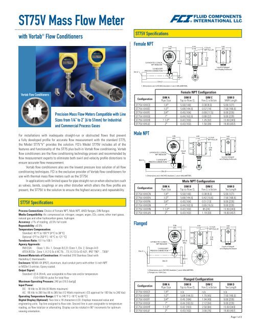
<strong>ST75V</strong> <strong>Mass</strong> <strong>Flow</strong> <strong>Meter</strong>with Vortab ® <strong>Flow</strong> Conditioners<strong>ST75V</strong> SpecificationsFemale NPTVortab <strong>Flow</strong> Conditioners<strong>ST75V</strong> SpecificationsPrecision <strong>Mass</strong> <strong>Flow</strong> <strong>Meter</strong>s Compatible with LineSizes from 1/4” to 2” [6 to 51mm] for Industrialand Commercial Process GasesFor installations with inadequate straight-run or obstructed flows that preventa fully developed profile for accurate flow measurement with the standard ST75,the Model ST75”V” provides the solution. FCI’s Model <strong>ST75V</strong> includes all of thefeatures and functionality of the ST75 plus built-in Vortab flow conditioning. Vortabflow conditioners are the flow conditioning technology proven and recommended byflow measurement experts to eliminate both swirl and velocity profile distortions toensure accurate flow measurement.Vortab flow conditioners also are the lowest pressure loss solution of all flowconditioning techniques. FCI is the exclusive provider of Vortab flow conditioners foruse with thermal mass flow meters such as the <strong>ST75V</strong>.In applications with limited space for pipe straight-run or when obstructors suchas valves, bends, couplings or any other disturber which alters the flow profile arepresent, the <strong>ST75V</strong> is the solution to ensure the highest accuracy and repeatability.Process Connections: Choice of Female NPT, Male NPT, ANSI flanges, DIN flangesMedia Compatibility: Air, compressed air, nitrogen, oxygen, argon, CO2, ozone, other inert gases,natural gas and other hydrocarbon gases, hydrogen.Accuracy: ±1% of reading, ±0.5% full scaleRepeatability: ±0.5%Temperature Compensation:Standard: 40 °F to 100 °F [4 °C to 38 °C]Optional: 0 °F to 250 °F [ -18 °C to 121 °C]Turndown Ratio: 10:1 to 100:1Agency Approvals:FM/CSA: Class 1, Div. 1, Groups B,C,D; Class 1, Div. 2, Groups A-DATEX/IECEx: Zone 1, II 2 G Ex d IIC T6…T3; II 2 D Ex tD A21, IP67 T90°…T300°Element Materials of Construction: All-welded 316 Stainless Steel withHastelloy-C thermowells.Enclosure: NEMA 4X [IP67], aluminum, dual conduit ports with either ½ inch NPTor M20x1.5 entries. Epoxy coated.Output Signal:Standard: (2) 4-20 mA, user assignable to flow rate and/or temperature(1) 0-1000 Hz pulse for total flowMaximum Operating Pressure: 240 psi [16.5 bar(g)]Input Power:DC: 18 Vdc to 36 Vdc (6 Watts maximum)AC: 85 Vdc to 265 Vac 85 to 265 Vac (12 Watts maximum) (CE approval for 100 Vac to 240 Vac)Operating Temperature Range: 0 °F to 140 °F [ -18 °C to 60 °C]Digital Display (Optional): Two-line x 16 characters LCD. Displays measured value andengineering units. Top line assigned to flow rate. Second line is user assignable to temperaturereading, as flow totalizer or alternating. Display can be rotated in 90° increments for optimumviewing orientation.ConfigurationMale NPTFlangedDIM APipe SizeFemale NPT ConfigurationDIM BTop to <strong>Flow</strong> CLDIM C<strong>Flow</strong> CL to BottomDIM DVMR Length<strong>ST75V</strong>-XXXCE 1/4″ 5.50 [140] 0.38 [9,5] 5.00 [127]<strong>ST75V</strong>-XXXEE 1/2″ 5.69 [144,5] 0.57 [14] 7.50 [190,5]<strong>ST75V</strong>-XXXFE 3/4″ 6.45 [164] 0.69 [17,5] 9.00 [229]<strong>ST75V</strong>-XXXGE 1″ 6.44 [163,5] 0.88 [22] 9.00 [229]<strong>ST75V</strong>-XXXHE 1 1/2″ 6.42 [163] 1.25 [32] 13.50 [343]<strong>ST75V</strong>-XXXJE 2″ 6.43 [163] 1.50 [38] 18.00 [457]ConfigurationDIM APipe SizeMale NPT ConfigurationDIM BTop to <strong>Flow</strong> CLDIM C<strong>Flow</strong> CL to BottomDIM DTee Length<strong>ST75V</strong>-XXXCN 1/4″ 5.50 [140] 0.38 [9,5] 5.00 [127]<strong>ST75V</strong>-XXXEN 1/2″ 5.69 [144,5] 0.42 [10,6] 7.50 [190,5]<strong>ST75V</strong>-XXXFN 3/4″ 6.45 [164] 0.51 [13] 9.00 [229]<strong>ST75V</strong>-XXXGN 1″ 6.44 [163,5] 0.65 [16,5] 9.00 [229]<strong>ST75V</strong>-XXXHN 1 1/2″ 6.42 [163] .95 [24] 13.50 [343]<strong>ST75V</strong>-XXXJN 2″ 6.43 [163] 1.19 [30] 18.00 [457]ConfigurationDIM APipe SizeFlanged ConfigurationDIM BTop to <strong>Flow</strong> CLDIM C<strong>Flow</strong> CL to BottomDIM DTee Length<strong>ST75V</strong>-XXXCF 1/4″ n/a n/a n/a<strong>ST75V</strong>-XXXEF 1/2″ 5.69 [144,5] 1.75 [45] 7.50 [190,5]<strong>ST75V</strong>-XXXFF 3/4″ 6.45 [164] 1.94 [49] 9.00 [229]<strong>ST75V</strong>-XXXGF 1″ 6.44 [163,5] 2.12 [54] 9.00 [229]<strong>ST75V</strong>-XXXHF 1 1/2″ 6.42 [163] 2.50 [64] 13.50 [343]<strong>ST75V</strong>-XXXJF 2″ 6.43 [163] 3.00 [76] 18.00 [457]Page 1 of 2
ORDERING GUIDE: <strong>ST75V</strong> <strong>Mass</strong> <strong>Flow</strong> <strong>Meter</strong> with Vortab ® <strong>Flow</strong> ConditionersModel <strong>ST75V</strong>-Base Unit, Enclosure Style (Block 1)Enclosures: All Aluminum, NEMA 4X/IP67 rated, epoxy coatedBlind, Integral Transmitter, with two 1/2″ FNPT cable entries 1Integral Transmitter with Local Digital Display, with two 1/2″ FNPTcable entriesRemote Transmitter w/ two 1/2″ FNPT cable entries and w/Digital Display.(Specify cable length in Block 10)Blind, Integral Transmitter, w/ two M20x1.5 cable entriesIntegral Transmitter with Local Digital Display, w/ two M20x1.5 cable entriesRemote Transmitter w/ two M20x1.5 cable entries and w/Digital Display.(Specify cable length in Block 10)Power Supply (Block 3)DC; 18 - 36 V 1AC; 85 - 265 V, 50/60 Hz 2Line Size (Block 4)1/4″ (Available only with NPT, Block 5 must be Code E or N) 5 C1/2″ E3/4″ F1″ G1-1/2″ H2″ JProcess Connection Type (Block 5)Female NPTMale NPTFlanged, #150 CLASSBlock No. 1 2 3 4 5 6 7 8 9 10Pipe Installation, Display/Transmitter Mounting Orientation and <strong>Flow</strong> Direction (Block 2)CodeHorizontal Pipe Code Vertical Pipe CodeTop mnt, display face frwd, flow L-R F Side mnt L, display face frwd, flow up MTop mnt, display face frwd, flow R-L G Side mnt R, display face frwd, flow up NSide mnt, display face up, flow L-R H Side mnt L, display face frwd, flow down PSide mnt, display face up, flow R-L J Side mnt R, display face frwd, flow down RSide mnt, display face down, flow L-R K For visual representation, refer to FCI drawingSide mnt, display face down, flow R-L L number 020943Other; agency approved, customer specified(If selected, Block 6 and 7 which follow must also be Code WW only)Process Connection Size, Material, Rating, Finish Details (Block 6 & 7)1/4″ NPT (must be selected if Block 4 is Code C) Q01/2″ NPT H03/4″ NPT T01″ NPT 101-1/2″ NPT B02″ NPT 201/2″ ANSI flanged 150 lb RF ANSI 16.5, 316L Stainless steel HG3/4″ ANSI flanged 150 lb RF ANSI 16.5, 316L Stainless steel TG1″ ANSI flanged 150 lb RF ANSI 16.5, 316L Stainless steel 1G1-1/2″ ANSI flanged 150 lb RF ANSI 16.5, 316L Stainless steel BG2″ ANSI flanged 150 lb RF ANSI 16.5, 316L Stainless steel 2GDN15 DIN flanged PN40, Form C per DIN2526 or Form B1 per DIN EN1092-1 in 316L ssDN25 DIN flanged PN40, Form C per DIN2526 or Form B1 per DIN EN1092-1 in 316L ssDN40 DIN flanged PN40, Form C per DIN2526 or Form B1 per DIN EN1092-1 in 316L ssDN50 DIN flanged PN16, Form C per DIN2526 or Form B1 per DIN EN1092-1 in 316L ssOther; agency approved, customer specified24ABCCodeCodeCodeENFWCodeD2E2G2J2WWGas Medium and System Calibration 2 (Block 8)AirAir Equivalence (Oxygen, Chlorine, Ammonia, etc.)Nitrogen, Helium, Argon, CO2, Compressed AirHydrocarbons (e.g. Natural Gas, Ethane, Methane, Propane, Ethylene,Propylene, Mixed)Hydrogen or hydrogen mixtureAir, Compressed AirAir Equivalence (e.g. Oxygen, Chlorine, Ammonia, etc.)Nitrogen, ArgonCO2, Ethylene, EthanePropane, PropyleneButane, PentaneMethane, Helium, Natural GasHydrogenCalibration 3 and Calibration Temperature Conditions (Block 9)High Accuracy 1% Calibration and Standard Conditions+40 °F to 100 °F [+4 °C to 38 °C] w/VortabHigh Accuracy 1% Calibration and Extended Temperature Compensation0 °F to 250 °F [-18 °C to 121 °C] w/VortabOther, Agency approved,customer specifiedInterconnecting Cable Length for Remote Configurations 4 (Block 10)Not required (Specify with integral configuations) 010′ [3 meters] A25′ [7,6 meters] B50′ [15 meters] CCustom length (Cannot exceed 50 ′ [15 meters])Part NumberDescription019819-01 Software Interface Package for PDA/PalmOS020802-01 PDA, Palm ® model Tungsten TM E2FC88Portable Hand-held Communicator014108-02 PC Interface Communications Kit, For RS232 serial port connectionDM10-NDM10-FCDM10-KIT1DM10-KIT2DM15DM15-ALMDM20NotesDigital Display/Readout, LCD, 4-20 mA loop powDM10 with FM and CSA approvalsPanel Mount Kit for DM10Optional Accessories2 inch (52 mm) Pipe Mount Kit for DM10 (Stainless steel)Digital Display/Readout, LED 115/230 Vac poweredSame as DM-15 with user programmable alarm limit, relay outputDigital Display Readout, 8-digit LCD Pulse totalizer/counterCodeBCEFGHJKLMNPRCodeQTWCode2. Must use FCI’s AVAL program to determine letter code. AVAL is a custom flowmeter optimizer program which considers gas medium, flow range, pipe size andother conditions to determine best calibration and supplies FCI letter code to beused here. AVAL is available on-line at www.fluidcomponents.com or consult localFCI representative/distributor.3. Calibration accuracy is ±% of reading, ±0.5% of full scale.4. Fixed cable length with instrument calibrated together as a matched set.Cable may be coiled, but not cut.5. Certified Material Test Report (CMTR) not available with <strong>ST75V</strong> 1/4″.WLocally Represented By:0409 0KVisit FCI on the Worldwide Web: www.fluidcomponents.comHeadquarters: 1755 La Costa Meadows DriveSan Marcos, California 92078 USAPhone: 760-744-6950 Toll Free: 800-854-1993 Fax: 760-736-6250European Office: Persephonestraat 3-01 5047 TT Tilburg, The NetherlandsPhone: 31-13-5159989 Fax: 31-13-5799036FCI is ISO 9001:2000 and AS9100 CertifiedDoc. No. 02MK011529D© Copyright 2009 by Fluid Components International LLC. All rights reserved. Manufactured in accordance with one or more of the following patents: US Patent Numbers: 4,929,088, 4,967,593, 4,981,368, 4,994,780, 5,111,692,5,600,528, 5,780,737, 5,913,250, 6,208,254, 6,340,243, 6,628,202, 6,843,110, China Patent Number: ZL00815586.0. FCI is a registered trademark of Fluid Components International LLC. Information subject to change without notice.