Aerospace - Interstate Connecting Components
Aerospace - Interstate Connecting Components
Aerospace - Interstate Connecting Components
- No tags were found...

Create successful ePaper yourself
Turn your PDF publications into a flip-book with our unique Google optimized e-Paper software.
AMPHENOL’S WIDE RANGE OF CONTACTSMEET THE DEMANDS OF MILITARY ANDAEROSPACE APPLICATIONS.Leading in the electrical connection arena, Amphenolproducts are used on major programs of military andcommercial aircraft, military ground vehicles, spaceapplications, missiles/ordnance, and C4ISR equipment.
Amphenol contacts are designed and qualified to a number ofmilitary specifications and standards. Always striving to meetor exceed customer needs, Amphenol is a leader in contactmanufacturing.For over 50 years,Amphenol <strong>Aerospace</strong>has been in the forefrontof interconnect designand manufacturing foraerospace and harshenvironmentapplications.Engineers work with customers to definethe proper circuitry for a connectorusage - shielding protection, highfrequency protection, combinations ofcontact types in one shell - theoptimum design for your application.Amphenol’s high technology computerdriven centers for connector andcontact production result in qualityproduction and cost reductions withshorter lead and delivery times.
TABLE OF CONTENTSAmphenol ® High Frequency Contacts Catalog Product Overview.......................1-6Cable Usage Guide...........................................................................................7-10Subminiature Cylindrical Connector Overview..................................................... 11Quadrax Contacts for MIL-DTL-38999, Series III Cylindricals.........................12-14Differential Twinax Contacts for MIL-DTL-38999, Series III Cylindricals..........15-16Compliant Quadrax Contacts and PC Tail Quadrax Contactsfor Attachment to PC Boards............................................................................ 17Quadrax Transition Adapters and Differential Twinax Transition Adapters......18-20Insert Patterns - for MIL-DTL-38999,Series III CylindricalsIncorporating quadrax and differential twinax contacts................................21-22How to Order MIL-DTL-38999, Series III Cylindricals with Quadrax100 ohm contacts............................................................................................. 23Coaxial Contacts for Subminiature Cylindricals...............................................24-27Matched Impedance Coaxial Contacts for Subminiature Cylindricals................... 28Typical Contact Installation Instructions for Coax Contacts.................................. 29High Frequency Contacts for MIL-DTL-38999, Series III Cylindricals................... 30Twinax Contacts for Subminiature Cylindricals...............................................31-33Triax Contacts for Subminiature Cylindricals........................................................ 34Coax, Twinax & Triax PC Tail Contacts for Subminiature Cylindricals.............35-37Insert Patterns - Subminiature CylindricalsIncorporating coax, twinax and triax contacts..............................................38-40Standard MIL-DTL-5015, Heavy Duty MIL-DTL-22992Cylindrical Connectors Overview...................................................................... 41Coaxial Contacts for Standard MIL-DTL-5015, Heavy DutyMIL-DTL-22992 Cylindricals........................................................................42-43Insert Patterns - Standard MIL-DTL-5015, Heavy DutyMIL-DTL-22992 Cylindricals, Incorporating coax contacts................................ 44Rectangular Connector OverviewPrinted Circuit Board and LRM Interconnects................................................... 45Coax Contacts for RectangularsPrinted Circuit Board and LRM Interconnects................................................... 46Rectangular Connector OverviewRack and Panel Connectors............................................................................. 47Quadrax, Differential Twinax, Coax & Twinax Contactsfor Rack and Panel Connectors........................................................................ 48Additional Contact Styles from Amphenol.......................................................49-50Guide for Selecting High Frequency Contacts and Cables................................... 51Amphenol Sales Office and Distributor Listing...............................inside back coverThe Amphenol Corporationis known as the SystemDesigner’s Choice forelectrical and optical connectionswhen performance,quality and high reliabilityare paramountBreakaway Failsafe D38999Connector with coax andpower contacts38999 Connectorwith Quadrax ContactsIf more information on Amphenol <strong>Aerospace</strong> capabilities in contacts and interconnectproducts, or to speak with an applications engineer about a particular projectusing high frequency contacts, please consult us at:Amphenol CorporationAmphenol <strong>Aerospace</strong>40-60 Delaware AveSidney, New York 13838-1395Phone: 800-678-0141 or 607-563-5011Fax: 607-563-5157www.amphenol-aerospace.comAmphenol <strong>Aerospace</strong> operates a Quality System that is third-party certified toISO-9001:2000 and AS9100.New High Frequency 38999Connector with special size 8coax contacts that provideDC to 40 GHz microwaveperformance
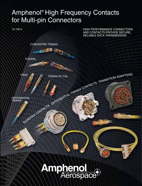
Amphenol ® High Frequency Contactsprovide high speed transmission andoperate in high frequency conditionsWhen you need superior electrical performance plus shielding to eliminateinterference from outside electrical sources in a connector, Amphenol has themost reliable contact solutions.Amphenol offers a very wide range of contacts that provide high speed transmissionand operate in high frequency conditions. You can be assured of interconnectioncompatibility when you come to Amphenol for your contact needs as well asyour connector needs. Amphenol’s expertise in interconnection solutions assuresthat your contacts will mate properly and will perform to the application specificationsof your particular requirements.MIL-DTL-38999 CONNECTORS - The high performance series most ideal forintegrating high speed and high frequency contacts. MIL-DTL-38999, Series I, IIand III are by far the choice of connector for today’s avionics needs - thesesubminiature family connectors are ideally suited for the incorporation ofshielded contacts.This catalog is primarily devoted to the high speed and high frequency contactoptions for use in MIL-DTL-38999 Connectors, which include:CoaxialConcentricTwinaxTriax Quadrax DifferentialTwinaxHighFrequencyTransitionAdaptersPin and socketcontactsdesigned forRF/microwaveand shieldedwire applications.Sizes 4,8, 12 & 16Pin and socketcontacts designed forprotection frommagnetic and electrostaticinterferenceincluding nuclearelectromagneticpulse. Sizes 8 & 12Pin and socketcontactsdesigned forshielded wireapplicationswith 3conductors.Sizes 8, 10 & 12Size 8 pin and socketcontacts. An outercontact with 4strategically spacedinner contacts formingtwo 100 or 150 Ohmmatched impedancedifferential pairs.Size 8 pin and socketcontacts. An outercontact with 2 innercontacts spaced toform one 100 or 150Ohm matchedimpedance differentialpair.Size 8 Coaxialcontacts that providehigh frequencies (DCto 40 GHz). Unique“Float Mount”technology maintainstight mechanicaltolerances.Matched impedancequadrax and twinaxtransition adaptersprovide a method oflaunching from thehigh speedconnectors to PCBboards.Other series of connectors from Amphenol <strong>Aerospace</strong>, in addition to 38999 connectors, canincorporate shielded contacts. These include the following (and are also covered in thiscatalog):• Amphenol ® Heavy Duty Cylindrical Connectors, MIL-DTL-22992 - with coax contacts.• Amphenol ® Printed Circuit Board Connectors - Rectangular connectors with standard lowmating force brush contacts can have hybrid arrangements with coax contacts.• LRM Interconnects - Rectangular module and backplane connectors with standard lowmating force brush contacts can have hybrid arrangements with coax contacts.• Amphenol ® ARINC 600 and R27 Rack & Panel Connectors are available with quadrax,coax, twinax and differential twinax contacts.The Cable Usage Guide is a key reference to help guide you in selecting the contacts bestsuited to your needs. Since most shielded wire applications start with a fixed requirement forcable types, the guide refers you to the Amphenol connector family utilizing contacts whichare compatible with the cable characteristics.See High Frequency ContactDesigner’s Guideat end of this catalog.For more information on other Amphenol connectors with shielded contacts:• Amphenol ® Miniature Cylindrical Connectors, MIL-DTL-26482, Series 1 are available withcoaxial contacts, size 8 and 12 for crimp and solder type. See catalog 12-070 on-lineat www.amphenol-industrial.com, or consult Amphenol Industrial Operations.• Amphenol ® MS/Standard, MIL-DTL-5015 Cylindrical Connectors are available with size4, 8 and 12 coax contacts. Consult Amphenol Industrial Operations for more information.For more information on connectors with fiber optics:• See catalog 12-352, Amphenol ® Fiber Optic Interconnect Products for Military, <strong>Aerospace</strong>and Harsh Environments, on-line at www.amphenol-aerospace.com, or consult Amphenol<strong>Aerospace</strong>.1
High Speed Quadrax andDifferential Twinax ContactsDifferential Twinax and Quadraxcontacts provide high data transferrates, low power consumption,and excellent EMI capability. Theyoffer controlled impedance of 100or 150 Ohm and are ideal for use inharsh environments.Amphenol provides the latest technology in high speed contacts - differentialtwinax and quadrax contacts, size 8, for use in MIL-DTL-38999 Special*Subminiature Cylindrical Connectors.DIFFERENTIALTWINAX CONTACTSHigh speed Differential Twinax contactsconsist of an outer contact with two innercontacts spaced to form one 100 or 150 Ohmcontrolled impedance differential pair. Seepages 15 and 16 for performance data andordering of Differential Twinax contacts, andconsult Amphenol <strong>Aerospace</strong> for moreinformation.QUADRAX CONTACTSHigh speed Quadrax contacts consist of anouter contact with four inner contactsspaced to form two 100 or 150 Ohmcontrolled impedance differential pair.Both contacts, when used in AmphenolMIL-DTL-38999 Series III and ARINC typeconnectors, provide an excellent alternativefor harsh environment applications such as:• Ethernet 100 Base-T-100 Ohm• Gigabit Ethernet 1000 Base-T-100 Ohm• Fibre Channel-150 Ohm• IEEE1394B FireWire-110 OhmDifferential Twinax ContactQuadrax ContactDifferential Twinax and Quadrax contact options include:• Crimp or printed circuit board termination• Established designs to accommodate a variety of cable types and gages• Ground plane connectors can incorporate quadrax contacts. These connectionshave conductive inserts that ground the outer conductor of the contactbody to the shell of the connector. They accommodate size 8 and 12 shieldedcontacts of which the size 8 can be quadrax type.See pages 12-14 for performance data of Quadrax contacts. Consult Amphenol<strong>Aerospace</strong> for further information needed.D38999 Series IIIConnectors(standoff shell atright and standardshell below) withQuadrax PC TailContactsD38999 Series IIIGround PlaneConnectors withQuadrax PCBSocket contactsD38999 Series IIIwith Quadrax andPower Contacts* Requires modified connector to accommodate keyed contacts.2
Quadrax Contacts, QuadraxTerminators, Transition AdaptersQUADRAX CONTACTS FORARINC CONNECTORSAmphenol ARINC 600 Rack and Panelconnectors can incorporate high speedquadrax contacts as well as coax, twinaxand differential twinax contacts. R27 Rackand Panel connectors use the samecontacts as ARINC 600 connectors. SeeCable Usage Guide and see pages 47and 48 for more information on these rackand panel connectors.BOARD LEVEL CONNECTORSWITH COMPLIANT QUADRAXCONTACTSAmphenol also provides compliantquadrax socket contacts and Quadrax pincontacts with PC tails for attaching toprinted circuit boards. See page 17 formore information.Quadrax Contact forARINC ConnectorsCompliant Quadrax Socketand PCB Tail Quadrax PinBoard Level Connectorwith CompliantQuadrax ContactsFEED-THROUGH CONNECTORWITH QUADRAX CONTACTSAmphenol’s feed-through connector isdouble-ended for through bulkheadapplications. Consult Amphenol for moreinfomation.Straight QuadraxReceptacle ContactQuadrax TerminatorsAmphenol offers a terminatorassembly which is a lowreactance, resistiveimpedance match to thecharacteristic impedance ofa transmission line. It isused to terminate the far ends of a transmissionline or an open tap so that the energy from signalstraveling down the transmission line is absorbedwithin the resistor and not reflected back down thetransmission line causing signal interference(noise). Consult Amphenol for more information.Quadrax Terminator90° Quadrax Receptacleand Plug TransitionAdapterTransition AdaptersIn conjunction with its Differential Twinax and Quadrax contacts,Amphenol has developed a full line of Transition Adapters in orderto facilitate launching of controlled impedance signals to printedcircuit boards. These use differential twinax or quadrax 90° orstraight receptacles and they can be either threaded or cable toboard direct. The threaded transition adapters provide an idealmethod of disconnecting the differential twinax or quadraxconnector from the board. See pages 18-20 for furtherdescription, performance data and ordering of transitionadapters.90° Differential TwinaxReceptacle and PlugTransition Adapter3 3
Coax Contacts with FrequencyRange of DC to 40 GHzHIGH FREQUENCY COAXCONTACTS WITH “FLOATMOUNT” TECHNOLOGYAmphenol <strong>Aerospace</strong> now offers DCto 40 GHz size 8 coaxial contacts forthe D38999 housing and standardinserts. These contacts can beterminated to a multiple of cable typesdepending on the application.High Frequency Size 8 Coax Contactswith “Float Mount TechnologyBy using standard interfaces that are based on MIL-STD-348 and can beinstalled in any D38999 size 8 insert, Amphenol has transformed the circularconnector industry. This technology expands the use of D38999 connectors toinclude the microwave transmission lines within the multi-port configurationwithout change to a custom connector.The high frequencies are maintained by Amphenol’s unique “Float Mount”technology. This technology allows for consistent microwave performance whilemaintaining tight mechanical tolerances. This consistency provides superiorelectrical performance and, unlike other blindmate connectors, will maintain anaccurate phase length when mated. See page 30 for specifications, performancesand ordering of this contact.Twinax Contacts for PrintedCircuit Board ApplicationsPC TAIL TWINAXCONTACTSAmphenol provides PrintedCircuit Tail Twinax contacts forMIL-DTL-38999 Series I and IIIcylindrical connectors and alsofor ARINC 404 and ARINC 600rectangular connectors. Highreliability is assured with factorypre-assembled contacts andstandardized termination to theboard.Variety of PC Tail Twinax ContactsSee pages 35-37 for performance data and ordering of PC tail twinax contacts,and consult Amphenol <strong>Aerospace</strong> for further information needed. Also seeAmphenol catalog 12-170, Cylindrical Connectors for Printed Circuit Boards, orCatalog 12-C1, Amphenol’s new combined 38999 catalog.Shielded Triax ContactsTRIAX CONTACTS WITH THREECONDUCTORS FOR USE WITHTRIAX CABLEAmphenol supplies sizes 8, 10 and 12triax contacts for use in MIL-DTL-38999Series I, II and III connectors. Triax contactsprovide additional shielding when terminated to triaxcable having solid or stranded center conductors. See cable compatibility in theCable Usage Guide and performance data and ordering of triax contacts onpages 34-37. Each of the three conductors of the triax contact is separated bydielectric insulation to isolate ground planes and to improve shielding effectiveness.All conductors are crimp terminated for high reliability and ease ofassembly. Triax contacts may be specified for direct connection to printed circuitboards. For maximum system flexibility, triax contacts may be mixed with coax,twinax and power contacts in a single connector.Triax ContactsHF38999 - D38999 Connectors withHigh Frequency Coax ContactsD38999 Connectorswith PC TailTwinaxContactsPrinted Circuit Twinax Contactsprovide a cost effective packagingsolution for limited space applicationswhere connectors are attached toprinted circuit boards.Rail Launch MIL-STD-1760Connector withTriax Contacts5 5
Cable Usage GuideUse the Cable Usage Guide on pages 7-9 as follows:1. Locate the cable you are using in Cable Type column. For cables not listed consult Amphenol <strong>Aerospace</strong>.2. Refer to the Amphenol Connector section which features contacts/adapters for this cable. Connector size, performancefeatures and insert pattern availability may influence your choice.3. Order your connector and contacts or transition adapters by following the procedure given in the section for theconnector series selected. These instructions are supplemented by the Amphenol Catalog Section covering the basicconnector.Quadrax ContactsCABLE USAGE GUIDED38999 Series III* ConnectorsCable TypeDraka Fileca F-4703-3F-4703-4F-4704-5F-47-4-6Filotex ET2PC236ET2PF870PIC Wire E50424E50426E51424Tensolite NF22Q100NF24Q100NF24Q100-1NF24Q100-01-200CNF26Q100NF26Q100-1NF26-2Q10024443/03130X-4(LD)24443/03166X-4(LD)24443/9P025X-4(LD)23450/04090X-4 (LD)24443/C20714X-4(LD)Gore RCN7688RCN8513S280W502-4JSF-18-3Themax 956-4TN956-5T956-4T200MX100Q-24Tensolite 24450/03089X-4(LD)Gore RCN8487JSFY02-1JSF18Tensolite 26473/02006X-4(LD)Gore RCN8328NominalImpedance(ohms)100110150Differential Twinax ContactsCABLE USAGE GUIDED38999 Series III* ConnectorsNominalCable TypeImpedance(ohms)Tensolite 26463/70460X-2ST5M1284-00398Draka Fileca 2709-3PIC Wire E10224Tensolite NF24T100-200C Space23460/05114X-2(LD)24463/03220T-2(LD)24463/05099X-8(LD)26453/03184X-2(LD)24463/9P025X-2(LD)100Raychem 0026A0024, 0024G0024S280W502-6JSFY11-24Gore GSC-05-827300-00Thermax 956-6262, 956-1T20012814MX 100-24Tensolite 26483/03071X-2(LD) 150Quadrax Transition AdaptersCABLE USAGE GUIDED38999 Series III* Connectorsor ARINC 600 ConnectorsNominalCable TypeImpedance(ohms)Draka Fileca F-4703-3F-4704-4Tensolite NF22Q100NF22Q100-01NF24Q100100NF26Q100Thermax 956-5Gore GSC-10-8273900Tensolite 26473/02006X-4(LD) 150* Requires modified connector to accommodate keyed contacts.7Differential Twinax Transition AdaptersCABLE USAGE GUIDED38999 Series III* Connectorsor ARINC 600 ConnectorsNominalCable TypeImpedance(ohms)M17/176-00002 78Tensolite 224463/9P025X-224463/9P025X-2(LD)100Tensolite 26483/03071X-2 150
Cable Usage Guide, cont.Quadrax ContactsCABLE USAGE GUIDEARINC 600 Rack & Panel ConnectorsNominalCable TypeImpedance(ohms)Draka Fileca F-4703-3F-4704-5, F4704-4Tensolite NF22Q100NF24Q10010024443/03130X-4(LD)24443/9P025X-4(LD)S280W502-4JSFY02-1 110Gore RCN8328150Tensolite 26473/02006X-4(LD)Differential Twinax ContactsCABLE USAGE GUIDEARINC 600 Rack & Panel ConnectorsCable TypeNominalImpedance(ohms)ABS0386WF24 100ASNE0272TK22 100ASNE0272TK24 100Tensolite 24463/9P025X-2(LD) 100Concentric Twinax ContactsCABLE USAGE GUIDED38999 Series I, II, III & SJT ConnectorsCable TypeNominalImpedance(ohms)EPD32263A 77EPD22189B 77M17/176-00002 77GSC-12-2548-00 77GC875TM24H 77GSC-12-81095-00 77Raychem 10602 7710606 7710612 7710613 7710614 7723089/RC 7705A0771 77T10971 777724C8664 777726D0664 77782OD0111 (20 AWG) 780024G0024 1005M2022-003 100HS5930 100S280W502-1 100CXN2268 100Triax ContactsCABLE USAGE GUIDED38999 Series I, II, III & SJT ConnectorsCable TypeNominalImpedance(ohms)JN1088WT 505M2397-002 7581264-02 75JN1088WU 75Gore GSC-03-81497-00 75RG179 (Coax Cable) 75Tensolite 28988/50823LXX-1 75Tensolite 28988/50823LXX-1 75Thermatics 12447 7510602 (Twinax Cable) 775M2559-001 9581264-01 95ST5M1323-001 95Champlain 81-00700 95Tensolite 28598/9C026LT-1 9526895/90334X-1 95Teledyne 13809 9511914/1 95Times AA6603 95Concentric Twinax ContactsCABLE USAGE GUIDEARINC 600 Rack & Panel ConnectorsCable TypeNominalImpedance(ohms)S280W502-1 1008
Cable Usage Guide, cont.Use the Cable Usage Guides on this page for Coax Contacts as follows:1. Locate the cable you are using in Cable Type column. For cables not listed consult Amphenol <strong>Aerospace</strong>.2. Refer to the Amphenol connector section which features contacts for this cable, as indicated by a • in the appropriatecolumn. If more than one connector series utilizes contacts designed for your cable, investigate each of them.Connector size, performance features and insert pattern availability may influence your choice.3. Order your connector and coax contact by following the procedure given in the section for the connector seriesselected. These instructions are supplemented by the Amphenol Catalog Section covering the basic connector.4. The Additional Contacts column of this guide is used to indicate an additional availability of contact designs for oldercable types or capability. Consult Amphenol <strong>Aerospace</strong> for further information.Coax ContactsCABLE USAGE GUIDECable TypeNominalImpedance(ohms)For SubminiatureCylindricals(MIL-DTL-38999 type)9For Standard & HeavyDuty Cylindricals(MIL-DTL-5015 type)(MIL-DTL-22992 type)For RectangularConnectorsAdditionalContacts(ConsultAmphenol)RG-5B/U (M17/073-RG212) 50 •RG-6A/U (M17/2-RG6) 75 •RG-7/U 97 •RG-9B/U (M17/075-RG214) 50 •RG-11A/U (M17/6-RG11) 75 •RG-12A/U (M17/6-RG12) 75 •RG-13A/U 74 •RG-21A/U 53 •RG-55B/U (M17/084-RG223) 53 • •RG-58C/U (M17/028-RG058) 50 • •RG-58 (M17/155-00001) 50 •RG-59B/U (M17/29-RG59) 75 •RG-62A/U (M17/030-RG062) 93 •RG-62B/U 93 •RG-63B/U (M17/31-RG63) 125 •RG-71B/U (M17/90-RG71) 93 •RG-87A/U 50 •RG-115/U 50 •RG-115A/U 50 •RG-116/U 50 •RG-122/U (M17/054-RG122) 50 • •RG-133A/U (M17/100-RG133) 95 •RG-140/U (M17/110-RG302) 75 •RG-141A/U 50 • •RG-142A/U 50 • • •RG-142B/U (M17/060-RG142) 50 • • • •RG-143A/U 50 •RG-161/U 70 • •RG-174A/U (M17/119-RG174) 50 • •RG-178B/U (M17/093-RG178) 50 • •RG-179B/U (M17/094-RG179) 75 • •RG-180B/U (M17/095-RG180) 95 • • •RG-187A/U (M17/094-RG179) 75 • •RG-188A/U (M17/113-RG316) 50 • •RG-188 Double Braid 50RG-195A/U (M17/095-RG180) 95 • • •RG-195 Double Braid 95RG-196A/U (M17/169-00001) 50 • •RG-210/U 93 •RG-212/U (M17/073-RG212) 50 • •RG-214/U (M17/075-RG214) 50 •RG-216/U (M17/77-RG216) 75 •RG-222/U 50 •RG-223/U (M17/084-RG223) 50 • • •RG-225/U (M17/86-RG225) 50 •RG-227/U 50 •RG-302/U (M17/110-RG302) 75 •CHART CONTINUES ON NEXT PAGENOTE: For information on coax contacts for Miniature cylindricalconnectors, MIL-DTL-26482 Series 1, see catalog 12-070 and consultAmphenol Industrial Operations.NOTE:MIL-DTL-38999 supersedes MIL-C-38999.MIL-DTL-5015 supersedes MIL-C-38999.MIL-DTL-22992 supersedes MIL-C-22992
Cable Usage Guide, cont.Coax ContactsCABLE USAGE GUIDE, cont.Cable TypeNominalImpedance(ohms)For SubminiatureCylindricals(MIL-DTL-38999 type)For Standard & HeavyDuty Cylindricals(MIL-DTL-5015 type)(MIL-DTL-22992 type)For RectangularConnectorsAdditionalContacts(ConsultAmphenol)RG-303/U (M17/111-RG303) 50 • •RG-304/U (M17/112-RG304) 50 •RG-316/U (M17/113-RG316) 50 • •RD-316Double Braid(M17/152-00001) 50 •RG-400 (M17/128-RG400) 50 •M/A-COM 5M2869-001 50 • •5022A1311-D 50 •Beldon 9307 50 •FA-19X 50 •T-Flex-402 50 •T-Flex-405 50 •Filotex ET124962 50 •JN1088WT (Triax) 50 •JN1088WU (Triax) 75 •PAN6422XQ 50 •PAN6422XY 75 •PAN6595XM (Triax) 75 •Haveg 51-04486 •81-00207 •Gore GWN1159A •CXN3403•Times AA3248 •Teledyne 11299 •Raychem 5021D1331-0 50 •5021D1331-9 50 •5022D1312-9 50 •7527A1318 75 •9527A1314 95 •9528A1318 95 •9530A5314 95 •9530D5314 95 •Thermatics 2929-29 •Tensolite 30850/87T-1 •Thermax 50C-25A-DS-1 •For Cable not found in the Coax Contact Cable Usage Guide, refer to these general dimensional ranges:(In general, for D38999 Connectors, the size 8, 12 and 16 Coax Contacts will terminate cable in the following ranges )SIZE 16.012 / .0215 Center Conductor (Standed).031 / .066 Dielectric.085 Max Outer braid (must be round for crimp termination).102 Max. JacketSIZE 12.012 / .0215 Center Conductor (Standed).031 / .105 Dielectric.126 Max Outer braid (must be round for crimp termination).145 Max. JacketSIZE 8.012 / .0395 Center Conductor (Standed).055 / .133 Dielectric.180 Max Outer braid (must be round for crimp termination).201 Max. JacketSpecial coax contacts may be available for cables outside of ranges shown. Consult Amphenol <strong>Aerospace</strong> for furtherassistance in selection of coax contact cables.10
Subminiature Cylindrical ConnectorOverviewAmphenol ® Subminiature Connectors are ideally suited for the incorporation ofshielded contacts for high performance interconnection applications. The Subminiaturefamily is built around MIL-DTL-38999 specifications, with Mil-approved andproprietary styles offered. Normal operating voltage for Subminiatures with powercontacts only is up to 900 VAC (RMS) at sea level.Subminiature Cylindricals offer these features for contact termination flexibility:• Widest selection of insert arrangements that can incorporate:• size 8 high speed Quadrax and Differential Twinax contacts for MIL-DTL-38999 Series III(specially modified to accommodate keyed contacts)• Transition adapters for use in attaching D38999 Series III connectors with high speedTV-R, Tri-Start, D38999 Series IIIquadrax or differential contacts to PCB boardsSee Catalog 12-092 or Catalog 12-C1* for• size 8, 12 and 16 Coax contactscomplete information on this series.• size 8 and 12 Twinax contacts• High performance capability series for bothgeneral duty and severe environment• size 8, 10 & 12 Triax contactsappli cations• Wide selection of connector shell styles and sizes• Offers the widest range of Subminiature• Scoop-Proof recessed design in LJT-R, TV-R and SJT-R connectors provide protection for Fam ily Mil-Spec qualified options in contactcontactsand connector styles• Threaded coupling; completely mates in one• Standard power contacts are crimp rear release, qualified to SAE AS39029turn; crimp termination• Coax, Twinax, and Triax contacts employ the same retention system as power contacts, • Superior EMI/EMP shielding effectivenesssimplifying user substitution• Scoop-proof design (recessed pins)• Available in aluminum, stainless steel andfirewall, or lightweight composite stylesGENERAL ORDERING INFORMATIONAmphenol Subminiature Cylindricals, which featurerear removable contacts, are normally supplied witha full complement of power contacts, separatelypackaged. Coax, twinax and triax contacts areordered by part number as referenced in the partnumber charts on the fol lowing pages of thiscatalog, and are substituted for the power contactsat the time of the cable or equipment assembly. Ifthe application is for coax, twinax or triax contactsonly, the connector may be ordered less contactsJT-R, D38999 Series IILJT-R, D38999 Series Iand no power contacts will be supplied.See Catalog 12-090 or Catalog 12-C1* for See Catalog 12-090 or Catalog 12-C1* forcomplete information on this series.complete information on this series.• Shorter profile connector series for applica • Scoop-proof (recessed pins)HOW TO ORDER CONNECTORS ANDtions requiring maximum space savings • Bayonet coupling, crimp terminationHIGH FREQUENCY CONTACTS• Bayonet coupling, crimp termination• Also available in solder termination typesA. Select the Subminiature Series desired.• Also available in solder termination types under MIL-DTL-27599 Series II(See features of each series given briefly onunder MIL-DTL-27599 Series IIthis page and in-depth in series catalogs, whichare on-line at www.amphenol-aerospace.com).Catalog 12-090* - JT-R, LJT-R ConnectorsCatalog 12-092* - TV-R ConnectorsCatalog 12-091* - SJT-R ConnectorsCatalog 12-C1* - Combined 38999 Cylindrical ConnectorsCatalog 12-094 - Amphe-Lite (Industrial 38999 type)B. Select the quadrax, differential twinax, coax, twinax and/or triaxcontacts or the transition adapters that are needed from thetables on the follow ing Subminiature Cylindrical pages thatcorrespond to the cable being used.Amphe-Lite, 38999 Type SJT-R, 38999 TypeC. Select the insert arrangement to accommodate required number See Catalog 12-094 for complete See Catalog 12-091 or Catalogof contacts. Insert patterns for quadrax and differential twinaxinformation on this series.12-C1* for complete information oncontacts are on pages 21, 22. Insert patterns for coax, twinax• Commercial/Industrial 38999 this series.and triax contacts are on pages 38-40.Series III type• Amphenol proprietary seriesD. Complete the connector part number from the connector series • Cost effective high performance (non-MS) which is a furtherconnector for severe environmentsor general duty industrial but incorporates the LJTexpansion of the basic JT family,catalog, incorporating the chosen insert pattern number.See detailed how to order page 23 for ordering 38999, Series IIIapplicationsscoop-proof designwith quadrax and differential twinax contacts. Consult Amphenol • Consult Amphenol Industrial • Compliant with several Europeanfor assistance in ordering 38999 cylindricals with coax, twinaxOperations for further information specificationsand triax contacts.E. Consult Amphenol <strong>Aerospace</strong> for ordering information forNOTE: SAE AS39029 supersedes MIL-C-39029.connectors with PC tail contacts, and for transition adapters.NOTE: MIL-DTL-38999 supersedes MIL-C-38999.F. If connector is ordered less contacts, power contacts and/orMIL-DTL-27599 supersedes MIL-C-27599sealing plugs may be ordered separately to fill out the insert* New Amphenol Catalog 12-C1 will combine 38999 Series I, II and IIIarrangement.and SJT Series in one catalog. It will also include 38999 with Filter/11Transient Protection and with PC Tails.
Quadrax Contacts for MIL-DTL-38999, Series IIICylindricalsgeneral descriptionAmphenol ® Quadrax Contacts offer several advantagesfor high data transfer rates, low power consumption and excellentEMI compatibility:• Four strategically spaced inner contacts form two 100 or 150 Ohmmatched impedance differential pairs• Outer contact has rugged wall section for durability• Available in size 8 crimp termination style• Also available in size 8 with PC tails (see page 14)• Requires modification of MIL-DTL-38999 connector toaccommodate keyed contacts(4) CENTERCONDUCTORSBRAIDJACKETTYPICAL QUADRAXSOCKET CONTACT hassocket outer contact with asocket inner contactINSULATIONTYPICAL QUADRAX PIN CONTACThas pin outer con tact with a pin innercontactCable Illustration - Quadrax ContactQuadrax Pin with 8P8C “RJ45” JackQuadrax Pin Size 8 and MIL-DTL-38999Series III ConnectorQuadrax Contacts are gold plated, crimpterminationFinish of mating contacts parts: supplied with0.000050 min. gold over nickel on matingparts. Consult Amphenol for availability ofother finishes.Quadrax Size 8 Contact Performance:• Bandwidth: Up to 3 Gigahertz• Data Rate: Exceeding 3 Gbits/sec.• Voltage Rating: 500 Vrms max. @ sea level• Dielectric Withstanding Voltage:1000 VAC rms between all inner contacts @sea level500 VAC rms between inner and outercontacts @ sea levelQuadrax in an Eight Wire Gigabit Ethernet AssemblySuggested Numbering for QuadraxContactsORIENTATIONKEYSuggested Strain Relief - Insert Arrangements 9-5 or 19-18with Quadrax ContactsDue to the piggyback grommet interference with normal strain reliefs on theshell size 9 only, the recommendedstrain relief for the connector is:Amphenol part number TGW-R-5309-10 (OD Cad) or TGF-R-5309-10 (Electroless nickel) -shell size 9 only.For 19-18 insert pattern, recommendedbackshell: Glenair367-221-NF. This is recommendeddue to the proximity of the size 8contacts in relation to the shell..367 MAX..525MAX.PIGGYBACKGROMMET4312PIN CONTACTMATING FACE2314SOCKET CONTACTMATING FACESee page 23 for part number ordering of popularlyused 38999 Series III connectors with 100 ohmquadrax contacts.Also see Quadrax contacts for ARINC 600 and R27 Rack and Panel Connectors onpage 47 and 48.12
Quadrax Contacts for MIL-DTL-38999, Series IIICylindricalsapplication dataTV-R Series, MIL-DTL-38999 Series III* ConnectorsQUADRAX CONTACTS FOR USE IN TV-R CONNECTORSCableDraka Fileca F-4703-3, F4704-4, Filotex ET2PC236, Filotex ET2PF870, PIC Wire E50424ABS0972, Tensolite 23450/04090X-4(LD)Tensolite NF24Q100, NF24Q100-01,24443/9P025X-4(LD), S280W502-4,24443/03130X-4(LD), 24443/C20714X-4(LD),24450/0120X-4(LD),NF24-2Q100, TYCO CEC-RWC-18664, GOREGSC-01-81869-01, 24443/03166X-4(LD),Thermax T956-4T200, Pic Wire E51424,Thermax MX100Q-24, NF24Q100-01-200C(Space), PIC E50424Tensolite NF22Q100, NF22Q100-01,Thermax956-5, Draka Fileca F-4704-5, GORE RCN7688, ABS1503 KD 24Tensolite NF26Q100, NF26Q100-01,NF26-2Q100, PIC E50426NEXANS ET 132552, Tensolite24443/03130X-4LD92607 altered key (innercontacts box pattern, mates with 21-3338( )-81only)Draka Fileca F-4704-6Tensolite NF24Q100-01 (same as 21-3338( )-51, uses EMI Piggyback)Gore RCN8513, JSFY18-3Tensolite NF22Q100 Special Box pattern, onlymates with 21-333( )-181Tensolite NF24Q100, NF24Q100-01 for 2.5Gbps applicationsUSB2 (28433/02171LX-4)Tensolite 24450/03089X-4(LD)Contact Part Number(Termination InstructionSheet)**Pin21-33384-21(L-2119-A)21-33384-51(L-2119-D)21-33384-61(L-2119-H)21-33384-71(L-2119-AB)21-33384-81(L-2119-R)21-33384-151(L-2119-AW)21-33384-161(L-2119-BE)21-33384-171(L-2119-BN)21-33384-181(L-2119-BP)21-33384-191(L-2119-BS)Socket21-33385-21(L-2119-A)21-33385-51(L-2119-D)21-33385-61(L-2119-H)21-33385-71(L-2119-AB)21-33385-81(L-2119-R)21-33385-151(L-2119-AW)21-33385-161(L-2119-BE)21-33385-171(L-2119-BN)21-33384-181(L-2119-BP)21-33385-191(L-2119-BS)21-33384-101† 21-33385-101†21-33384-211 21-33385-211Impedance(Ohms)100InnerContactConductorSize(AWG)2424222624262422228ElectricalProtocol††Ethernet, 1000 Base-T GigabitEthernetEthernet, 1000 Base-T GigabitEthernetEthernet (100 Mbps), 1000 Base-TGigabit Ethernet (1 Gbps)Ethernet (100 Mbps), 1000 Base-TGigabit Ethernet (1 Gbps)Ethernet (100 Mbps), 1000 Base-TGigabit Ethernet (1 Gbps)Ethernet (100 Mbps), 1000 Base-TGigabit Ethernet (1 Gbps)Ethernet (100 Mbps), 1000 Base-TGigabit Ethernet (1 Gbps)Ethernet (100 Mbps), 1000 Base-TGigabit Ethernet (1 Gbps)Ethernet (100 Mbps), 1000 Base-TGigabit Ethernet (1 Gbps)24 Serial FPDP Applications (2.5 Gbps)90 USB2.0 (480 Mbps)24 IEEE 1394B FirewireCrimping ToolsInnerContactM22520/2-01with PositionerM22520/2-37or with DanielsPositioner K709OuterContactM22520/5-01with Die SetM22520/5-45(Location A)JSFY02-1, JSFY1821-33384-221 21-33385-22124 IEEE 1394B FirewireGore RCN8487, JSFY1821-33384-231 21-33385-23111024 IEEE 1394B FirewireTensolite 24450/03089X-4(LD) Same as21-3338( )-211 but Box pattern, mates with21-3338( )-241 onlyTensolite 26473/02006X-4(LD)/Gore RCN8328(not for new designs, use 21-33450/1 series)21-33384-241† 21-33385-241†21-33384-31(L-2119-B)21-33385-31(L-2119-B)150 2624 IEEE 1394B FirewireCHART CONTINUES ON NEXT PAGEQUADRAX CONTACT DATAContacts are inserted by hand. Refer to termination instructions listed.Contacts are removed with a removal tool. Recommended tool isMIL-I-81969/14-06, Daniels DRK-264-8. Refer to termination instructions listed.Finish of mating contact parts: Contact part numbers shown in the chart aboveare sup plied gold plated per ASTM B488 Type II, Code C, .000050 min. thickover nickel plate per AMS-QQ-N-290, Class 2, .000030/.000150 thick.13CONTACT ORDERING: Example number given in chart 21-33384-21 shouldbe ordered as 21-033384-021; example number 21-33384-151 should beordered as 21-033384-151. Adding Zeros is necessary for Amphenolordering process on all contact numbersDaniels crimping tools are available from Daniels Mfg. Corp. 6103 AnnoAve., Orlando, FL 32809* Requires modified connector to accommodate keyed contacts.**Termination instructions are packaged with each contact and can befound on-line at: www.amphenol-aerospace.com/service instructions.asp† Consult Amphenol <strong>Aerospace</strong> for current release of this contact orinstruction sheet if applicable.†† Test reports available for indicated protocols. Consult Amphenol<strong>Aerospace</strong>.
Quadrax Contacts for MIL-DTL-38999, Series IIICylindricals, cont.application dataTV-R Series, MIL-DTL-38999 Series III* ConnectorsCableTensolite 26473/02006X-4(LD) Same as21-33384/5-31 but box pattern (not for newdesigns, use 21-33450/1 series)QUADRAX CONTACTS FOR USE IN TV-R CONNECTORSContact Part Number(Termination InstructionSheet)**PinTensolite 26473/02006X-4(LD), Gore RCN8328 21-33450-001(L-2119-BW)Tensolite 26473/02006X-4(LD), Gore RCN8328(same as 21-33450/1-1 except box pattern.Mates with 21-33450/1-11 only.Socket21-33384-201† 21-33385-201†21-33451-001(L-2119-BW)21-33450-011† 21-33451-011†Impedance(Ohms)150InnerContactConductorSize(AWG)2626268ElectricalProtocol††Fibre-Channel (1 GBPS, 2 GBPS,1G/2G), 1000 Base-CX (1.25GBPS), SCSI-2 (3.2 GBPS)Fibre-Channel (1 GBPS, 2 GBPS,1G/2G), 1000 Base-CX (1.25GBPS), SCSI-2 (3.2 GBPS)Crimping ToolsInnerContactM22520/2-01with PositionerM22520/2-37or with DanielsPositioner K709OuterContactM22520/5-01with Die SetM22520/5-45(Location A)PCB QUADRAX CONTACTS FOR USE IN TV-R CONNECTORSPCB QuadraxContact Part Number ImpedanceContactsPin Socket (Ohms)PCB (1.035 Length) Pre-tinned tails 21-33398-21 21-33397-21 100PCB (.866 Length) 21-33398-31 21-33397-31 100PCB Right Angle, inner contacts box pattern 21-33425-1 100PCB (.494 Length) Pre-tinned tails 21-33398-71 150PCB (1.194 Length) Pre-tinned tails 21-33398-101 100PCB (.859 Length) 21-33398-121 100PCB (.741 Length) 21-33398-271† 100PCB (1.035 Length) 21-33398-291 21-33397-291 100PCB (.836 Length) 21-33397-301 150PCB (1.035 Length) Pre-tinned tails 21-33398-61 21-33397-61 150PCB (1.035 Length) mates to 21-33451 series 21-33452-11† 150PCB (1.035 Length) mates to 21-33450 series 21-33453-11† 150PCB (.815 Length) mates to 21-33451 series 21-33452-21† 150PCB (.815 Length) mates to 21-33450 series 21-33453-21† 150PCB (.815 Length) Pre-tinned tails, mates to 21-33451 series 21-33452-31† 150PCB (.815 Length) Pre-tinned tails, mates to 21-33450 series 21-33453-31† 150PCB .866 Length) mates to 21-33451 series 21-33452-41† 150PCB (.866 Length) mates to 21-33450 series 21-33453-41† 150PCB (.494 Length) mates to 21-33451 series 21-33452-51† 150PCB (.494 Length) mates to 21-33450 series 21-33453-51† 150PCB (.840 Length) Pre-tinned tails 21-33398-81 150PCB (.780 Length) Pre-tinned tails 21-33398-131 150PCB (.840 Length) Pre-tinned tails 21-33398-91 100PCB (.708 Length) 21-33398-111 100PCB (.605 Length) 21-33398-191 100PCB (.494 Length) 21-33398-231 100PCB (.741 Length) 21-33398-241 21-33397-241 100PCB (.806 Length) 21-33398-281 100PCB (.940 Length) 21-33398-311 100PCB (.939 Length) 21-33398-361 100PCB (.672 Length) 21-33398-371 100PCB (.914 Length) 21-33398-381 100PCB (.866 Length) 21-33398-411 100PCB (.901 Length) 21-33397-341 100PCB (.871 Length) 21-33397-351 100PCB (1.169 Length) 21-33397-421 10014ContactSize8CONTACT ORDERING: Example number given in chartabove 21-33384-201 should be ordered as 21-033384-201; example number given in chart at left 21-33398-21should be ordered as 21-033398-021. Adding Zeros isnecessary for Amphenol ordering process on all contactnumbersDaniels crimping tools are available from Daniels Mfg.Corp. 6103 Anno Ave., Orlando, FL 32809* Requires modified connector to accommodatekeyed contacts.**Termination instructions are packaged with eachcontact and can be found on-line at:www.amphenol-aerospace.com/service instructions.asp† Consult Amphenol <strong>Aerospace</strong> for current releaseof this contact or instruction sheet if applicable.†† Test reports available for indicated protocols.Consult Amphenol <strong>Aerospace</strong>.SEALING PLUGSSealing Plugsfor use with D38999 Connectors usingQuadrax Contacts - Size 8 CavitiesStandard PlasticStandard Plastic to be used with PCB tails(shorter tail length)Metal sealing plug - can be used when matingwith contacts on mating halfMetal sealing plug used with PCB’s and matingcontact on mating halfPIGGYBACK GROMMETPart NumberT3-4008-59PT3-4008-59P121-33899-8Q121-33899-8Q2Grommet for use with D38999ConnectorsPart Numberusing Quadrax ContactsMetalized piggyback grommet 21-33321-23Indicated length given in chart at left is the distancefrom the rear of the contact retention shoulder to thetip of the PCB tails.LENGTHINDICATED INTABLE COLUMNNote: it does not indicate stickout length wheninstalled in D38999 connector.
Differential Twinax Contacts for MIL-DTL-38999,Series III Cylindricalsgeneral descriptionAmphenol ® Differential Twinax Contacts - offerseveral advantages for high data transfer rates, low powerconsumption and excellent EMI compatibility:• Two strategically spaced inner contacts form two 100 or 150 Ohmmatched impedance differential pairs• Outer contact has rugged wall section for durability• Available in size 8 crimp termination style• Also available in size 8 with PC tails (see page 16)• Requires modification of MIL-DTL-38999 connector toaccommodate keyed contacts(2) CENTERCONDUCTORSBRAIDJACKETTYPICAL DIFFERENTIALTWINAX SOCKETCONTACT has socketouter contact with asocket inner contactINSULATIONCable Illustration - Differential Twinax ContactTYPICAL DIFFERENTIALTWINAX PIN CONTACT haspin outer con tact with apin inner contactDifferential Twinax Socket ContactDifferential Twinax Contacts are goldplated, crimp terminationFinish of mating contacts parts: supplied with0.000050 min. gold over nickel on mating parts.Consult Amphenol for availability of otherfinishes.Differential Twinax Size 8 ContactPerformance:• Bandwidth: Up to 3 Gigahertz• Data Rate: Exceeding 3 Gbits/sec.• Voltage Rating: 500 Vrms max. @ sea level• Dielectric Withstanding Voltage:1000 VAC rms between all inner contacts @sea level500 VAC rms between inner and outercontacts @ sea levelDifferential Twinax Pin ContactSuggested Numbering for DifferentialTwinax ContactsORIENTATIONKEY2 1 1 2PIN CONTACTMATING FACESOCKET CONTACTMATING FACE15
Differential Twinax Contacts for MIL-DTL-38999,Series III Cylindricalsapplication dataTV-R Series, MIL-DTL-38999 Series III* ConnectorsDIFFERENTIAL TWINAX CONTACTS FOR USE IN TV-R CONNECTORSCableTensolite 24463/05099X-8(LD), Thermax MX100-24, Tensolite 24463/9P025X-2(LD),Thermax 12814, ST5M1284-003 (98 Ohm),26463/70460X-2 (98 Ohm), PIC E10224,Fileca 2709-3, NF24T100-200C (Space),S280W502-1GORE GSC-05-827300-00Tensolite 26453/03184X-2(LD), Thermax956-626Z, GORE GSC-05-827300-0023460/05114X-2(LD), PIC E1024Raychem 0026A0024, M17/176-00002 (77Ohm)JSFY11-24, Tensolite 24463/03220T-2(LD),Thermax 956-1T200S280W502-6, Tensolite 24463/9P026X-2(LD)Tensolite 26483/03071X-2(LD)Tensolite 26483/03071X-2(LD)Contact Part Number(Termination Instruction Sheet)**Pin21-33387-21(L-2119-E)21-33387-51***(L-2119-AY)21-33387-41(L-2119-T)21-33387-61(L-2119-BH)Socket21-33388-21(L-2119-E)21-33388-51***(L-2119-AY)21-33388-41(L-2119-T)21-33388-61(L-2119-BH)21-33387-71 21-33388-7121-33387-91(L-2119-BT)21-33387-101(L-2119-AK)21-33387-31(L-2119-AC)21-33456-1(L-2119-BX)†21-33388-91(L-2119-BT)21-33388-101(L-2119-AK)21-33388-31(L-2119-AC)21-33457-1(L-2119-BX)†Impedance(Ohms)100150ContactSize8Ethernet, USBElectricalProtocol††Fibre Channel, 1000 Base-CXEthernetCrimping ToolsInnerContactM22520/2-01with PositionerM22520/2-37or with DanielsPositioner K709OuterContactM22520/5-01with Die SetM22520/5-45(Location A)PCB DIFFERENTIAL TWINAX CONTACTS FOR USE IN TV-R CONNECTORSPCB QuadraxContact Part NumberContactsPinSocketPCB (1.035 Length) 21-33834-1 21-33835-1PCB (.788 Length) 21-33834-31 21-33835-31PCB (.494 Length) 21-33834-41 21-33835-41PCB (.939 Length) 21-33834-51 21-33835-51PCB (.780 Length) 21-33834-61 21-33835-61PCB (.871 Length) 21-33834-71 21-33835-71PCB (.937 Length) 21-33834-81 21-33835-81PCB (1.035 Length) 21-33834-91 21-33835-91PCB (.843 Length) 21-33834-101 21-33835-101PCB (.806 Length) 21-33834-111 21-33835-111PCB (.908 Length) 21-33834-121 21-33835-121PCB (.530 Length) 21-33834-131 21-33835-131PCB (.819 Length) 21-33834-141 21-33835-141Impedance(Ohms)PCB (1.035 Length) 21-33834-21 21-33835-21 150100ContactSizeDIFFERENTIAL TWINAX CONTACT DATAContacts are inserted by hand. Refer to termination instructions listed.Contacts are removed with a removal tool. Recommended tool is MIL-I-81969/14-06,Daniels DRK-264-8. Refer to termination instructions listed.Finish of mating contact parts: Contact part numbers shown in the chart above aresup plied gold plated per ASTM B488 Type II, Code C, .000050 min. thick over nickelplate per AMS-QQ-N-290, Class 2, .000030/.000150 thick.8CONTACT ORDERING: Example number given in chartabove 21-33387-21 should be ordered as 21-033387-021;example number given in chart left 21-33834-1 should beordered as 21-033834-001. Adding Zeros is necessary forAmphenol ordering process on all contact numbersDaniels crimping tools are available from Daniels Mfg.Corp. 6103 Anno Ave., Orlando, FL 32809* Requires modified connector to accommodate keyedcontacts.*** Indicated contact is vacuum degassed†† Test reports available for indicated protocols.Consult Amphenol <strong>Aerospace</strong>.**Termination instructions are packaged with each contactand can be found on-line at:www.amphenol-aerospace.com/service instructions.asp† Consult Amphenol <strong>Aerospace</strong> for current release of thisinstruction sheet.Indicated length given in chart at left is the distancefrom the rear of the contact retention shoulder to thetip of the PCB tails.LENGTHINDICATED INTABLE COLUMNNote: it does not indicate stickout length wheninstalled in D38999 connector.16
Compliant Quadrax Contacts and PC Tail QuadraxContacts for Attachment to PC Boardsgeneral descriptionAmphenol ® Quadrax Contacts for PrintedCircuit Board Attachment - available for MIL-DTL-38999Series III Cylindrical connectors with straight PC tail termination andwith compliant pin termination. These provide the ideal solution forbringing high speed data transmission to the board.MIL-DTL-38999, SERIES IIICONNECTOR WITH PC TAILCONTACTS. This arrangementhas 33 size 22D and 2 QuadraxPC tail contacts.MIL-DTL-38999, SERIES IIICONNECTOR WITH PC TAILCONTACTS. This arrangementhas 8 Quadrax PC tailcontacts.Compliant Pin Quadrax and PC Tail Quadrax ContactsAmphenol ® Quadrax Contacts for Rectangular Board LevelConnectors - incorporate the same size 8 Quadrax PCB contacts as used incylindrical 38999 connectors.• Size 8 Quadrax Compliant contacts with hole diameters:.025 ±.002 PTH Quadrax contact.040 ±.003 PTH shell groundingAccommodates backplane .125 inch min. thickness• Consult Amphenol <strong>Aerospace</strong> for availability of additional connector configurations4 POSITION BOARD LEVEL CONNECTOR WITH QUADRAX2.200 2.000.475.500.376.720Compliant Pin Quadrax Board Level Connector8 POSITION BOARD LEVEL CONNECTOR WITH QUADRAX3.6403.440.475.500H G F E D C B A A B C D E F G H.381.72017
Quadrax Transition Adapters andDifferential Twinax Transition Adaptersgeneral descriptionAmphenol ® Transition Adapters - are used to facilitatelaunching of controlled impedance signals to printed circuit boards.Amphenol provides transition adapters in both contact types:• Quadrax transition adapters, 90° or straight receptaclesthreaded or cable to board style• Differential twinax transition adapters, 90° or straight receptacles,threaded or cable to board styleQUADRAXTRANSITIONADAPTER PLUGQUADRAXTRANSITION ADAPTER90 DEGREE RECEPTACLE90° Quadrax Receptacle and Plug Transition AdapterSuggested Numbering for Transition Adapters withQuadrax Contacts1243TRANSITION ADAPTERPLUGMATING FACEORIENTATIONKEY90° Differential Twinax Receptacle and Plug Transition AdapterTRANSITION ADAPTER DATAFinish of mating contact parts: Contacts are sup plied gold plated perASTM B488 Type II, Code C, .000050 min. thick over nickel plate perAMS-QQ-N-290, Class 2, .000030/.000150 thick.4390° RECEPTACLETRANSITION ADAPTERMATING FACE1218Plug21-33836-31ELECTRICAL PROTOCOLS FORQUADRAX TRANSITION ADAPTERSPart NumberReceptacleImpedance(Ohms)ElectricalProtocol††Ethernet, gigabit Ether21-33836-41 Ethernet, gigabit Ether21-33836-51 Ethernet, gigabit Ether21-33836-61 Ethernet, gigabit Ether21-33837-10121-33836-2121-33837-111Plug21-33832-8121-33837-81 (90 degree)21-33837-91 (90 degree) 10021-33837-41 (90 degree)21-33837-51 (straight) Ethernet, gigabit Ether21-33837-61 (90 degree)21-33837-141 (90 degree)21-33837-21 (90 degree)21-33837-31 (straight)21-33837-71 (90 degree)1501000 Base CX,Fibre channel1000 Base CX,Fibre channelELECTRICAL PROTOCOLS FORDIFFERENTIAL TWINAX TRANSITION ADAPTERSPart NumberReceptacleImpedance(Ohms)21-33832-21 Ethernet21-33833-21 (90 degree)21-33833-31 (90 degree) Ethernet21-33833-151 (90 degree)21-33832-111†10021-33833-161† (90 degree)21-33833-171† (90 degree)21-33833-91 (90 degree)21-33833-51 (90 degree)21-33833-141 (90 degree)21-33832-9121-33833-111 (90 degree)15021-33833-181† (90 degree)21-33833-101 (90 degree)ElectricalProtocol††† Consult Amphenol <strong>Aerospace</strong> for current release of this adapter.††Test reports available for indicated protocols; consult Amphenol <strong>Aerospace</strong>.
Quadrax Transition Adaptersfor Attachment to PC Boardsapplication dataQuadrax Type Adapter/Cable or PCB Tail LengthQuadrax Plug Adapter/Tensolite NF24Q100Quadrax Plug Adapter/Tensolite NF22Q100, NF22Q100-01,Thermax 956-5Quadrax Plug Adapter/Draka Fileca F-4703-3, F-4704-4Quadrax Plug Adapter/NF26Q100Quadrax Receptacle Straight Adapterin-line jam nut (threaded)/GSC-10-8273900Quadrax Receptacle Straight Adapterin-line (threaded)/NF24Q100PCB Quadrax Receptacle 90 DegreeAdapter/Tail Length .110PCB Quadrax Receptacle StraightAdapter/Tail Length .110PCB Quadrax Receptacle StraightAdapter/Special Tail Length (.200)Quadrax Receptacle 90 degreeAdapter with cable to board/NF24Q100Quadrax Receptacle Straight Adapterwith cable to board/NF24Q100Mating plugs and receptaclesWired to board100 OHM QUADRAX TRANSITION ADAPTERSFOR LAUNCHING CONTROLLED IMPEDANCE SIGNALS TO PC BOARDSIllustration of AdapterPart NumberMating(Termination Instruction Sheet)** ImpedanceCrimping ToolsThread(Ohms)Plug Receptacle Size Inner Contact Outer Contact21-33836-31(L-2119-U)21-33836-41(L-2119-W)†21-33836-51(L-2119-Y)21-33836-61(L-2119-AM)†21-33837-81(L-2119-AR)†21-33837-91(L-2119-BL)21-33837-4121-33837-5121-33837-6121-33837-141(L-2119-BB)†21-33837-101(L-2119-AN)100 .375100M22520/2-01with PositionerM22520/2-37or withDaniels PositionerK709NAM22520/2-01with PositionerM22520/2-37or withDaniels PositionerK709M22520/5-01with Die SetM22520/5-45(Location A)NAM22520/5-01with Die SetM22520/5-45(Location A)150 OHM QUADRAX TRANSITION ADAPTERSFOR LAUNCHING CONTROLLED IMPEDANCE SIGNALS TO PC BOARDSQuadrax Type Adapter/Cable or PCB Tail LengthQuadrax Plug Adapter/Tensolite 26473/02006X-4(LD), GoreRCN8328PCB Quadrax Receptacle 90 DegreeAdapter/Tail Length .110PCB Quadrax Receptacle StraightAdapter/Tail Length .110Mating plugs and receptaclesIllustration of AdapterPart NumberMating(Termination Instruction Sheet)** ImpedanceCrimping ToolsThread(Ohms)Plug Receptacle Size Inner Contact Outer Contact21-33836-21(L-2119-S)21-33837-2121-33837-31150 .375M22520/2-01with PositionerM22520/2-34NANAQuadrax Receptacle 90 degreeAdapter with cable to board/Tensolite 26473/02006X-4Quadrax Receptacle Straight Adapterwith cable to board/Tensolite 26473/02006X-4 (LD)CONTACT ORDERING: Example number given in chart 21-33837-81should be ordered as 21-033837-081; example number 21-33837-101should be ordered as 21-033837-101. Adding Zeros is necessary forAmphenol ordering process on all contact numbers.Daniels crimping tools are available from Daniels Mfg. Corp. 6103 AnnoAve., Orlando, FL 32809Wired to board21-33837-71(L-2119-AI)†21-33837-111(L-2119-AP)150M22520/2-01with PositionerM22520/2-34M22520/5-01with Die SetM22520/5-45(Location A)** Termination instructions are packaged with each contact and can be found on-line at:www.amphenol-aerospace.com/service instructions.asp† Consult Amphenol <strong>Aerospace</strong> for current release of this adapter andinstruction sheet if applicable.See electrical protocols for transition adapters on page 18.19
Differential Twinax Transition Adaptersfor Attachment to PC Boardsapplication data100 OHM DIFFERENTIAL TWINAX TRANSITION ADAPTERSFOR LAUNCHING CONTROLLED IMPEDANCE SIGNALS TO PC BOARDSDifferential Twinax Type Adapter/Cable or PCB Tail LengthDifferential Twinax Plug Adapter/M17/176-00002 (77 ohms)Differential Twinax Plug Adapter/Tensolite 24463/9P025X-2(LD)PCB Differential Twinax Receptacle 90Degree Adapter/ Tail Length .110PCB Differential Twinax ReceptacleStraight Adapter/ Tail Length .110PCB Differential Twinax ReceptacleStraight Adapter/ Tail Length .165Mating plugs and receptaclesIllustration of AdapterPart NumberMating(Termination Instruction Sheet)** ImpedanceCrimping ToolsThread(Ohms)Plug Receptacle Size Inner Contact Outer Contact21-33832-81(L-2119-AJ)21-33832-21(L-2119-P)21-33833-2121-33833-3121-33833-151100 .3125M22520/2-01with PositionerM22520/2-34N/AM22520/5-01with Die Set M22520/5-05(Location B)N/ADifferential Twinax Plug Adapter/Tensolite CAN22TDT120 (120 Ohm)PCB Differential Twinax Receptacle 90degree Adapter/Tail Length .283PCB Differential Twinax ReceptacleStraight Adapter/Tail Length .283Mating plugs and receptacles21-33832-111†21-33833-161†21-33833-171†100 .375M22520/2-01with PositionerM22520/2-34N/AM22520/5-01with Die Set M22520/5-45(Location A)N/ADifferential Twinax Receptacle 90degree Adapter (low profile) with cableto board/ Tensolite 24463/9P026X-2Differential Twinax Receptacle 90degree Adapter with cable to board/Tensolite 24463/9P025X-2Differential Twinax Receptacle 90degree Adapter with cable to board/Tensolite 24463/9P025X-2Wired to board21-33833-91(L-2119-AF)21-33833-51(L-2119-V)21-33833-141(L-2119-BU)100 N/AM22520/2-01with PositionerM22520/2-34M22520/5-01with Die Set M22520/5-45(Location A)150 OHM DIFFERENTIAL TWINAX TRANSITION ADAPTERSFOR LAUNCHING CONTROLLED IMPEDANCE SIGNALS TO PC BOARDSDifferential Twinax Type Adapter/Cable or PCB Tail LengthIllustration of AdapterPart NumberMating(Termination Instruction Sheet)** ImpedanceCrimping ToolsThread(Ohms)Plug Receptacle Size Inner Contact Outer ContactDifferential Twinax Plug Adapter/Tensolite 26483/03071X-2PCB Differential Twinax Receptacle 90Degree Adapter/ Tail Length .110PCB Differential Twinax ReceptacleStraight Adapter/ Tail Length .110Mating plugs and receptacles21-33832-91(L-2119-BR)M22520/2-01with PositionerM22520/2-34M22520/5-01with Die Set M22520/5-45(Location A)150 .37521-33833-111 N/A N/A21-33833-181† N/A N/ADifferential Twinax Receptacle 90degree Adapter with cable to board/Tensolite 26483/03071X-2Wired to board21-33833-101(L-2119-BM)†150 N/AM22520/2-01with PositionerM22520/2-34M22520/5-01with Die Set M22520/5-45(Location A)CONTACT ORDERING: Example number given in chart 21-33832-21 shouldbe ordered as 21-033832-021; example number 21-338373-141 should beordered as 21-033833-141. Adding Zeros is necessary for Amphenol orderingprocess on all contact numbers.** Termination instructions are packaged with each contact and can be found on-line at:www.amphenol-aerospace.com/service instructions.asp† Consult Amphenol <strong>Aerospace</strong> for current release of this adapter andinstruction sheet if applicable.20 See electrical protocols for transition adapters on page 18.
Insert Patterns - for MIL-DTL-38999,Series III CylindricalsIncorporating quadrax and differential twinax contactsThis illustrated list ing represents the most readily availablepatterns incorporating quadrax and differential twinaxcontacts within D38999, Series III cylindrical connectors.If you require other arrangements than what are shown here,consult Amphenol for further availability. In most cases,unless otherwise stated, size 8 cavities can be filled withquadrax or differential twinax contacts. Arrangements can bemixed with any size 8 coax, and/or concentric twinax or triaxcontacts.CONTACT LEGEND8 10 12 16 20 22DQuadrax orDifferential Twinaxfront face of pin inserts illustrated1716DABA8710129 33011CB6 45Insert Arrangement 9-5 17-2 17-22 17-52 17-60Number of Contacts 1 38 1 2 2 2 8 2Contact Size 8 22D 8 Twinax 12 8 8 22D 8GroundedMeets BoeingSpecificationPNMLKRJHSATUGBCDEFV fWUhNSRAKMCBgE16 114 15 2 31312A4511 810 79 8DCABInsert Arrangement 19-18 19-31 19-AD 21-75Number of Contacts 14 4 12 1 2 16 1 4Contact Size 22D 8 22D 12 8 20 8 8RPSTABCDEFAB129 64227216794678524749418 3267 8141 5925 75N UMLKJHVGFEDC42 6019 3368 826 2653 76 99159321842878Insert Arrangement 21-79 23-6 25-7Number of Contacts 17 2 6 97 2Contact Size 22D 8 8 22D 821
Insert Patterns - for MIL-DTL-38999,Series III CylindricalsIncorporating quadrax and differential twinax contactsCONTACT LEGEND8 10 12 16 20 22DQuadrax orDifferential Twinaxfront face of pin inserts illustratedFGEAHBDCRPSNZTMaYULbKAcJBVdq r s ew tpfn v ugkm hXCDEWFGHSRP ZN Y 47M3XLKA BCT D516WHJU E2FVGInsert Arrangement 25-8 25-17 25-20Number of Contacts 8 36 6 10 13 3 4Contact Size 8 22D 8 20 16 8 12VUsrTqS pWtAARznmP ykNhMLAXBu Y CvZDabEwcFdx GegHfJK8 1DA7 26 3CB5 4Insert Arrangement 25-46 25-62Number of Contacts 40 4 2 8 4Contact Size 20 16 8 16 822
How to Order 38999, Series III CylindricalsWith quadrax 100 ohm contactsAmphenol Tri-Start, 38999 Series III* Connectors can beordered with the following popularly used Quadrax contacts:100 ohm quadrax 21-033385-051 socket contacts100 ohm quadrax 21-033384-051 pin contactsUse the following coded number ordering procedure :For ordering of connectors with any other quadraxcontacts or differential twinax contacts, please consultAmphenol <strong>Aerospace</strong> for part numbers.TVPS 00 RQW 21 – 75 P BConnector TypeShell TypeService ClassShell SizeInsert ArrangementContact TypeAlternate PositionsConnector TypeTV designates Tri-Start Series Connector with metal shellsTVP designates back panel mounted receptacle with metal shellsCTV designates Tri-Start Series Connector with composite shellsCTVP designates back panel mounted receptacle with compositeshellsShell Style00 designates wall mount receptacle02 designates box mount receptacle available only with thePCB tails and epoxy backfilled (non-removable)06 designates straight plug07 designates jam nut receptacleService Classes with QuadraxRQF electroless nickel plated aluminumRGQF electroless nickel plated ground plane aluminumRQW olive drab cadmium plateRGQW olive drab cadmium plated ground plane aluminumRQB NiAlBronzeRGQB NiAlBronze ground planeRQK corrosion resistance stainless steelRGQK stainless steel ground planeQDT Durmalon plated, Nickel-PTFE alternative to cadmiumShell Size / Insert ArrangementSee insert arrangements available with quadrax contacts onpreceding pages 21 and 22.Contact TypeP designates pin contactsS designates socket contactsAlternate PositionsLocksmith keying - rotation of minor keys. See Tri-Start AlternatePostions at right. “N” not required for normal postion* The incorporation of quadrax or differential twinax contacts requires amodified connector to accommodate keyed contacts.For more information on Tri-Start, MIL-DTL-38999 Series III connectorssee catalog 12-092 or catalog 12-C1. New Amphenol Catalog 12-C1 willcombine 38999 Series I, II and III and SJT Series in one catalog. It will alsoinclude 38999 with Filter/Transient Protection and with PC Tails23Tri-Start AlternatePositionsA plug with a given rotationletter will mate with areceptacle with the samerotation letter. The anglesfor a given connector arethe same whether itcontains pins or sockets.Inserts are not rotated inconjunction with themaster key/keyway.ShellSize911, 13,and 1517 and1921, 23,and 2525L, 33,and 37Key & KeywayArrangementIdentificationLetterNABCDENABCDENABCDENABCDENABCDEARBSC˚BRBSC˚DRBSC˚AR°orAP°BSC1051028035649195113905311951801354966627980135496662798013549666279CRBSC˚MAINKEYWAYPLUG(front face shown)BR°orBP°BSC140132118140155131141156145156146141142170169140145153142170169140145153142170169140145153RECEPTACLE(front face shown)MAINKEYWAYCR°orCP°BSC215248230205234197208182195220176184196200200200180197196200200200180197188188188188188188˚CPBSC˚APBSCBP˚BSC˚DPBSCDR°orDP°BSC265320312275304240236292252255298242293310244257280272293310244257280272293310244257280272
Coaxial Contacts for SubminiatureCylindricalsgeneral descriptionAmphenol ® Coaxial Contacts offer several advantagesfor reliable interconnection and continued performance:• Large crimping area assures low contact resistance and hightensile strength• Back insulator positively captivates inner contact againstaxial loads• Front insulator provides closed entry for socket inner contact• Recessed inner contact is protected• Outer contact has rugged wall section for durabilityTYPICAL SUBMINIATURE COAXSOCKET CONTACT has socket outercontact with a pin inner contactTYPICAL SUBMINIATURE COAXPIN CONTACT has pin outercon tact with a socket inner contactJacketInsulationLJT-R, JT-R, TV-R, SJT-R MS Type, CoaxSize 12 Socket Assembled ContactBraidCenterConductorCable Illustration - Coax ContactLJT-R, JT-R, TV-R, SJT-R MS Type, CoaxSize 16 Pin Unassembled ContactLJT-R, JT-R, TV-R, SJT-R MS Type, CoaxSize 8 Pin Assembled ContactCoax Contacts are gold plated, crimp terminationFinish of mating contacts parts: supplied with 0.000050 min. gold overnickel on mating parts. Other finishes are available; consult Amphenolfor further information.Coax Size 12 & 16 Contact Performance:• Typical VSWR: 1.5:1 maximum up to 700 MHz and 500 MHzrespec tively, for properly cabled size 12 and 16 coaxial contacts inthe M38999 Series I, II and III• Insulation Resistance: 5,000 megohms minimum @ 25°C• Dielectric Withstanding Voltage:Size 12: 1,000 VAC Rms @ sea level, 250 VAC Rms @ 50,000 ft.Size 16: 800 VAC Rms @ sea level, 250 VAC Rms @ 50,000 ft.• Contact Resistance: See MIL-C-39029/27, /28, /75, /76, /77, /78Coax Size 8 Contact Performance:• Typical VSWR when terminated to specified 50 ohm cable:1.5:1 maximum up to 3 GHz (excluding 21-33101/2-27)• Insulation Resistance: 5,000 megohms minimum @ 25°C• Dielectric Withstanding Voltage:1,300 VAC Rms @ sea level, 250 VAC Rms @ 50,000 ft.• Contact Resistance: See MIL-C-39029/59, /60LJT-R, JT-R, TV-R, SJT-R MS Type, CoaxSize 8 Socket Unassembled Contact24
Coaxial Contacts for SubminiatureCylindricalsapplication dataJT-R Series, MIL-DTL-38999 Series II,SAE AS39029 (27, 28, 76, 78)COAX CONTACTS FOR USE IN JT-R CONNECTORSCableContact Part Number(Termination Instruction Sheet)**ContactSizeCrimping ToolsInstallation ToolsRG-178B/U, RG-196A/UHaveg30-00761, 30-02024, 30-02033Tensolite24713/A955KK1, 26723/A955KK1Haveg 61-02051RG-174A/U, RG-188A/U, RG-161/U,RG-187A/U, RG-316/U, RG-179B/U,Haveg 8100207, Times (HS-179)AA3248, Teledyne 11299RG-180B/U, RG-195A/U,Raychem 9528A1318Raychem 5022E5111Raychem 9530A5314Raychem 9527A1318Gore GWN1159APin Socket Inner Contact Crimp Ferrule Insertion Removal21-33122-564(M39029/76-425)(L-2035-AG)21-33122-562†(L-2035-AN)21-33122-561†(L-2035-AK)21-33122-563(M39029/76-424)(L-2035-AD)21-33122-546(M39029/28-211)(L-2035-F)21-33122-541(M39029/28-409)(L-2035-C)21-33122-543†(L-2035-M)21-33122-544(L-2035-R)21-33122-545(L-2035-U)21-33122-547†(L-2035-X)21-33121-564(M39029/78-433)(L-2035-AH)21-33121-562†(L-2035-AP)21-33121-561†(L-2035-AL)21-33121-563(M39029/78-432)(L-2035-AE)21-33121-546(M39029/27-210)(L-2035-G)21-33121-541(M39029/27-402)(L-2035-E)21-33121-543†(L-2035-N)21-33121-544(L-2035-S)21-33121-545(L-2035-V)21-33121-547†(L-2035-Y)1612M22520/2-01with PositionerM22520/2-35or withDaniels Positioner K532M22520/2-01with PositionerM22520/2-34or withDaniels Positioner K323M22520/4-01with PositionerM22520/4-02M22520/31-01with PositionerM22520/31-02orDaniels GS-200 Toolwith PositionerG2P330M81969/8-07orM81969/14-03orAmphenol11-8674-1611-8794-16orMS27495A16orMS27534-16M81969/8-09orM81969/14-04orAmphenol11-8674-1211-8794-12orMS27495A12orMS27534-12M81969/8-08orM81969/14-03orAmphenol11-8675-1611-8795-16orMS27495R16orMS27534-16M81969/8-10orM81969/14-04orAmphenol11-8675-1211-8795-12orMS27495R12orMS27534-12CONTACT ORDERING: Example number given in chart 21-33122-564 should be ordered as 21-033122-564.Adding Zeros is necessary for Amphenol ordering process on all contact numbers† Consult Amphenol <strong>Aerospace</strong> for current release of this contact or instruction sheet if applicable.NOTE: SAE AS39029 supersedes MIL-C-39029**Termination instructions are packaged with each contact and can be found on-line at:www.amphenol-aerospace.com/service instructions.aspSUBMINIATURE CONTACT DATAAll contacts mate with other contacts in this series which have the same inner and outer contact diameters.JTExample: Socket 21-33121-564 on RG-196A/U cable will mate with pin 21-33122-563 on RG-188A/Ucable which is used in both this and the LJT-R series.LJT, TV, SJT,Amphe-LiteExample:Socket 21-33123-564 on RG-196A/U cable will mate with pin 21-33122-563 on RG-188A/Ucable which is used in both this and the JT-R series.Finish of mating contact parts: Contact part numbers shown in the chart above are sup plied with 0.000050 min.gold (Knoop hardness 130-200) over nickel on mating parts. Other finishes are available; consult Amphenol.Daniels crimping tools are available from:Daniels Mfg. Corp. 6103 Anno Ave., Orlando FL 3280925
Coaxial Contacts for SubminiatureCylindricalsapplication data, cont.LJT-R, MIL-DTL-38999 Series I; TV-R, MIL-DTL-38999 Series III; Amphe-Lite and SJT-R Series,SAE AS39029 (28, 59, 60, 75, 76, 77)COAX CONTACTS FOR USE IN LJT-R, TV-R, AMPHE-LITE AND SJT-R CONNECTORSCableRG-178B/U, RG-196A/UHaveg 30-00761, 30-02024,30-02033Tensolite 24713/A955KK1, 26723/A955KK1Haveg 61-02051RG-174A/U, RG-188A/U, RG-316/U,RG-161/U RG-187A/U, RG-179B/U,Haveg 8100207, Times (HS-179)AA3248, Teledyne 11299RG-180B/U, RG-195A/U,Raychem 9528A1318Raychem 5022E5111Raychem 9530A5314Raychem 9527A1318Raychem 9527A1314Gore GWN1159A, Nexans RG179-DTM/A-Com 5M2869-001RG-187A/U, RG-179B/U, RG-174A/U,RG-188A/U, RG-316/U, RG-161/UHaveg 8100207, Times (HS-179)AA3248, Teledyne 11299RG-142B/U, RG-223/UContact Part Number(Termination Instruction Sheet)**ContactSizeCrimping ToolsInstallation ToolsPin Socket Inner Contact Crimp Ferrule Insertion Removal21-33122-564(M39029/76-425)(L-2035-AG)21-33122-562†(L-2035-AN)21-33122-561†(L-2035-AK)†21-33122-563(M39029/76-424)(L-2035-AD)21-33122-546(M39029/28-211)(L-2035-F)21-33122-541(M39029/28-409)(L-2035-C)21-33122-543†(L-2035-M)†21-33122-544†(L-2035-R)21-33122-545†(L-2035-U)†21-33122-585(L-2035-GG)21-33122-547(L-2035-X)†21-33122-589(L-2035-GR)21-33102-23†(L-1107-C)21-33102-24*(L-1107-D)21-33123-564(M39029/77-429)(L-2035-AJ)21-33123-562†(L-2035-AR)†21-33123-561†(L-2035-AM)†21-33123-563(M39029/77-428)(L-2035-AF)21-33123-546(M39029/75-416)(L-2035-H)21-33123-541(M39029/75-417)(L-2035-D)21-33123-543†(L-2035-P)21-33123-544†(L-2035-T)†21-33123-545†(L-2035-W)21-33123-585(L-2035-GH)21-33123-547(L-2035-Z)†21-33123-589(L-2035-GT)21-33101-23†(L-1107-G)21-33101-24*(L-1107-H)16128M22520/2-01with PositionerM22520/2-35or withDaniels Positioner K532M22520/2-01with PositionerM22520/2-34or withDaniels Positioner K323M22520/2-01with PositionerM22520/2-31††or solderM22520/4-01with PositionerM22520/4-02M22520/31-01with PositionerM22520/31-02orDanielsGS-200 Toolwith PositionerG2P330M22520/5-01with die setM22520/5-03 (A)or M22520/5-08 (A)M22520/5-35 (B)or M22520/10-01with Die SetM22520/10-05 (A)M22520/5-01with die setM22520/5-05 (A)or M22520/5-19 (B)or M22520/10-01with Die SetM22520/10-07 (A)M81969/8-07orM81969/14-03orAmphenol11-8674-1611-8794-16orMS27495A16orMS27534-16M81969/8-09orM81969/14-04orAmphenol11-8674-1211-8794-12orMS27495A12orMS27534-12handinsertedM81969/8-08orM81969/14-03orAmphenol11-8675-1611-8795-16orMS27495R16orMS27534-16M81969/8-10orM81969/14-04orAmphenol11-8675-1211-8795-12orMS27495R12orMS27534-1211-9170orMSNOTE: SAE AS39029 supersedes MIL-C-39029CRIMPING TOOLS: Italicized letters in parenthesis that follow positioner partnum bers indicate applicable die closure. Commercial equivalents with the samedie clo sure dimension may be used.CHART CONTINUES ON NEXT PAGECONTACT ORDERING: Example number given in chart 21-33122-564 shouldbe ordered as 21-033122-564; example number 21-33102-23 should beordered as 21-033102-023. Adding Zeros is necessary for Amphenol orderingprocess on all contact numbers† Consult Amphenol <strong>Aerospace</strong> for current release of this contact or instructionsheet if applicable.†† When inner contact is installed by crimping only. 11-10134 Expander ToolKit must be used to assemble rear insulator over contact.**Termination instructions are packaged with each contact and can be foundon-line at: www.amphenol-aerospace.com/service instructions.asp26
Coaxial Contacts for SubminiatureCylindricalsapplication data, cont.LJT-R, MIL-DTL-38999 Series I; TV-R, MIL-DTL-38999 Series III; Amphe-Lite and SJT-R Series,SAE AS39029 (28, 59, 60, 75, 76, 77), cont.COAX CONTACTS FOR USE IN LJT-R, TV-R, AMPHE-LITE AND SJT-R CONNECTORS, CONT.CableContact Part Number(Termination Instruction Sheet)***ContactSizeCrimping ToolsInstallation ToolsPin Socket Inner Contact Crimp Ferrule Insertion RemovalHaveg 51-03111, Tensolite 28895/2X1RG-180B/U, RG-195A/U,Raychem 9528A131821-33102-22(L-1107-B)21-33102-21(M39029/60-367SupersedesMS27536)(L-1107-A)21-33101-22(L-1107-F)21-33101-21(M39029/59-366SupersedesMS27535)(L-1107-E)M22520/2-01with PositionerM22520/2-31**or solderM22520/5-01with die setM22520/5-05 (B)or M22520/5-41 (B)or M22520/10-01 withDie SetM22520/10-07 (B)RD-316 Double Shield(M17/152-00001)21-33102-25(L-1107-J)21-33101-25(L-1107-N)M22520/2-01with PositionerM22520/2-31M22520/5-01with Die SetM22520/5-37 (B)orM22520/10-01with Die SetM22520/10-15 (A)RG-400, ECS3C058ARG-58 (M17/155-00001),M17/028-RG-05821-33102-27(L-1286-B21-33102-29(L-1107-AA)21-33101-27(L-1293-B)21-33101-29(L-1107-Y)†8M22520/2-01with PositionerM22520/2-10SolderM22520/5-01with Die SetM22520/5-45 (A)M22520/5-01with Die SetM22520/5-05 (B)handinserted11-9170 or MS5021D1331-05M2869-0015022A1311-021-33102-36(L-1107-P)21-33102-37(L-1107-V)21-33102-39(L-1107-AC)21-33101-36†(L-1107-Q)21-33101-37(L-1107-W)21-33101-36†(L-1107-AB)M22520/2-01with PositionerM22520/2-31M22520/5-01with Die SetM22520/5-05 (B)orM22520/10-01with Die SetM22520/10-07 (B)FA-19X21-33652-1(L-2091-A)21-033653-1(L-2091-B)M22520/2-01with Positioner K1106M22520/5-01with Die Set Y25 (B)T Flex-40221-33102-41(L-1107-AG)21-33101-41(L-1107-AF)SolderM22520/5-01with Die SetM22520/5-05 (B)NOTE: SAE AS39029 supersedes MIL-C-39029NOTE: Contacts can be ordered by part numbers given in chartCRIMPING TOOLS: Italicized letters in parenthesis that follow positioner partnum bers indicate applicable die closure. Commercial equivalents with the samedie clo sure dimension may be used.CONTACT ORDERING: Example number given in chart 21-33102-22 should beordered as 21-033102-022; example number 21-33652-1 should be ordered as21-033652-001. Adding Zeros is necessary for Amphenol ordering process on allcontact numbers.† Consult Amphenol <strong>Aerospace</strong> for current release of this contact or instructionsheet if applicable** When inner contact is installed by crimping only. 11-10134 Expander ToolKit must be used to assemble rear insulator over contact.***Termination instructions are packaged with each contact and can be foundon-line at: www.amphenol-aerospace.com/service instructions.asp27
Matched Impedance Coaxial Contactsfor Subminiature CylindricalsAmphenol ® Matched Impedance Size 12 Coaxial ContactsFor RF/Microwave, High Frequency andHigh Performance RequirementsThe matched impedance coax contact is available in size 12.It incorporates a captivated inner contact which “snaps into”the outer contact preventing displacement or pull backof the inner contact in situations where the cable maybe bent.TYPICAL MATCHED IMPEDANCECOAX SOCKET CONTACThas socket outer contact with a captivatedpin inner contactTYPICAL MATCHED IMPEDANCECOAX PIN CONTACThas pin outer contact with a captivatedsocket inner contactDesign features and benefits of the Matched Impedance:• For use in 90 degree angle or bent cable applications• Provides 50 ohm matched impedance resulting in low VSWR and lowinsertion loss• Frequency range for a mated pair extends to 3 GHz and beyond,higher than other coaxial contacts previously offered.• Ideally suited for D38999 high performance and MIL-STD-1760 highband coaxial contact requirementsHigh Performance Size 12 Coax50 Ohm matchedLJT-R, MIL-DTL-38999 Series I, JT-R, MIL-DTL-38999 Series II, andTV-R, MIL-DTL-38999 Series IIIUse with CableRG316,T-Flex-405RG-316,T-Flex-405RD316,Filotex,ET124962,M17/152-00001JN1088WTPinComment(TerminationInstruction Sheet)***M39029/102/103 21-33651-11(L-2092-C)JT-R, MIL-DTL-38999Series IIM39029/102/103 TypeJN1104*50C21-33651-17(L-2092-F)21-33213-42PAN6422XQ PAN6841*50C 21-33651-12(L-2092-E)RG178,Gore CXN 3403RG178,Gore CXN 3403M39029/102/103 Type 21-33651-18(L-2092-K)JT-R, MIL-DTL-38999Series IISFT-316-TR M39029/102/103 Type 21-33651-22(L-2092-N)Socket(TerminationInstruction Sheet)***21-33650-11(L-2092-C)21-33729-11(L-2092-P)21-33650-17(L-2092-F)21-33214-42(L-2092-D)21-33650-1221-33650-18(L-2092-K)21-33729-18(L-2092-K)21-33650-22(L-2092-N)* Add P or S for pin or socketCONTACT ORDERING: Example number given in chart 21-33651-11 should be orderedas 21-033651-011. Adding Zeros is necessary for Amphenol ordering process on allcontact numbers.***Termination instructions are packaged with each contactand can be found on-line at:www.amphenol-aerospace.com/service instructions.asp28Matched Impedance Coax Contact Performance:Electrical Specifications:• Contact impedance = 50 ohms nominal• Frequency range = 0–3 GHzOperable at higher frequencies depending on cableselection. Consult Amphenol for details.• Dielectric withstanding voltage(for a mated pair):At sea level = 1000 VRMSAt 50, 000 ft. = 250 VRMS• Insulation resistance: 5 gigaohms min. @ 25°C• VSWR: 1.20 + .04F (F in GHz) max. up to 3 GHz• Insertion Loss: .11 fGHz dB max.Environmental Specifications:• Thermal limits: –55 ° to 200°CMechanical Specifications:• Mating: slide-on• Mounting: conforms to M39029/102 & /103envelope dimensions
Typical Contact Installation Instructionsfor Coax ContactsThe following is an example of a contact instruction sheet that would be shipped within the package of contacts for a Crimp, Size 12Coax Con tact for use in Subminiature, D38999 connectors. The sheet provides detailed instructions for assembling the componentparts and for crimping the contact to coaxial cable, along with the recommended cable and tooling to be used. Installation instructionsare included within all contacts for D38999 connectors. For installation instructions for other connector series, there are separatedocuments (not included in packaging of parts) as follows: L- 633 for Miniature solder types, L-613 for Miniature SE types, L-660 forMiniature CE types, and L-650 for MS/Standard and Heavy Duty types. For any other instructions needed, consult Amphenol.Most installation instructions can be found on-line at www.amphenol-aerospace.com (from home page, go to Service Instructions andenter contact part number or instruction sheet number).21-33651-11 (PIN)21-33650-11 (SOCKET)Contact, Pin and Socket, Coaxial,Type LJT-R & TV-R, (MIL-DTL-38999 Series I & III) Crimp, Size 12Installation InstructionsSee table on reverse side for coaxial cable recommended and crimptool information.A. 1. Slide outer crimp ferrule over cable outer jacket as shown.2. Strip cable outer braid as illustrated. Ends must be cut cleanlyand at right angles to the axial plane of the cable. The cablemust not be deformed while making cuts.3. Flare outer braid, then strip cable dielectric as shown.B. 1. Assemble inner contact assembly over cable center conductorand cable dielectric until inside bore of bushing butts againstcable dielectric.2. Cable center conductor must be visible through the inspectionhole in the inner contact wire well.3. Crimp inner contact wire well using crimp tool listed in table.C. 1. Carefully slide outer contact assembly over inner contactassembly and under cable outer braid until inner contact buttsagainst insulator shoulder as illustrated. (Inner contactassembly will snap into the locked position when fully assembledinside the outer contact assembly.)2. Bring outer crimp ferrule forward over cable outer braid asillustrated. (Continue to push the inner contact assembly fullyforward while bringing the outer crimp ferrule into position.)3. Crimp outer crimp ferrule using crimp tool listed in table ( .156Max. over ferrule after crimping). Trim excess braid ahead ofcrimp ferrule, if necessary.CONTACT INSERTION INTO CONNECTORUsing insertion tool (part number M81969/8-09 or M81969/14-04),insert contact assembly into rear connector grommet hole. Contactmust be aligned with hole and not inserted at an angle. Push forwarduntil contact is felt to snap into position within insert. Remove tool.CONTACT REMOVAL FROM CONNECTORPosition removal tool (part number M81969/8-10 or M81969/14-04)around cable and slide tool down wire until tool tips enter rear grommetand come to a positive stop. Hold tool tip firmly against positivestop on contact, grip wire and simultaneously remove tool, contact andcable.L-2092-COctober 2001FSCM7782021-33651-11 (PIN)21-33650-11 (SOCKET)CABLEDIELECTRIC.135 .195.165CABLECENTERCONDUCTORCABLEDIELECTRICCABLE CENTER CONDUCTORINNER CONTACT ASSEMBLY(SOCKET SHOWN FOR REFERENCE)INSPECTION HOLEOUTER CONTACT ASSEMBLY(PIN SHOWN FOR REFERENCE)INNER CONTACTMUST BUTT INSULATOR.330 REF.CABLEOUTER BRAID.165REF.CABLE DIELECTRICMUST BUTTBUSHING.010 / .030CABLE DIELECTRICAmphenol <strong>Aerospace</strong>OUTER CRIMP FERRULECABLE OUTER BRAIDOUTER FERRULECCABLEOUTER BRAIDBCABLEOUTER JACKETA 1 & A2A3AMPHENOL CORPORATIONAmphenol <strong>Aerospace</strong>40-60 Delaware AvenueSidney, New York 13838-1395www.amphenol-aerospace.comToolsAmphenol ®Part NumberDescriptionCoaxial CableAccommodatedCrimp ToolInner ContactSettingPositioner(Daniels)ToolOuter ContactPositioner21-33651-1121-33650-11Matched Impedance*Size 12 CoaxPinMatched Impedance*Size 12 CoaxSocketRG316(M17/113-RG316)RG179(M17/094-RG179)RG316(M17/113-RG316)RG179(M17/094-RG179)MH992 (Daniels) 5 K1360MH992 (Daniels) 4 K1360MH992 (Daniels) 5 K1360MH992 (Daniels) 4 K1360M22520/5-01M22520/5-03 (A)orM22520/5-35 (B)* Matched Impedance applies when contacts are terminated to RG316 cable only.29
High Frequency Contacts for MIL-DTL-38999,Series III Cylindricalsgeneral descriptionAmphenol ® High Frequency ContactsAmphenol and SV Microwave (an Amphenol company) offer DC to 40 GHzhigh frequency size 8, 12 and 16 coaxial contacts for the D38999 Series IIIhousing and standard inserts. These contacts allow any application tocontinue to use the D38999 connector and be able to expand the use toinclude the microwave transmission lines. Features include:• Superior electrical performance and high frequency capability• Blindmate advantage and maintance of an accurate phase length when mated• Can be terminated to a multiple of cable types depending on the application• Uses standard interfaces based on MIL-STD-348, and can be installed in anyMIL-DT-38999 size 8, 12 or 16 insert• Unique “Float Mount” technology allows for consistent microwave performancewhile maintaining tight mechanical tolerancesHIGH FREQUENCY CONTACTS30Subminiature MIL-DTL-38999 Series III Connectorwith Size 8 High Frequency ContactsHIGH FREQUENCY COAX CONTACTSFOR USE IN D38999, SERIES III CONNECTORSSPECIFICATIONSElectricalHigh Frequency(Mated pair size 8 - RG 405 Semi-Rigid Cable) Amphenol Part NumberInter-(Termination Instruction Sheet)faceFrequencyFor usewith CableTypeImpedance50 W21-033449-01HFFrequency RangeDC - 40 GHzSocket(300-17-008)BMZ 40 GHZ TFLEX-405VSWR1.05 +.01 (freq. GHz)21-033448-01HFInsertion Loss0.03. (freq. GHz)(300-17-008)PinInsulation Resistance (Min.) 10,000 M W21-033449-02HFSocket(300-89-009)Contact Resistance (Max.)BMZ 18 GHZ TFLEX-40521-033448-02HFcenter conductor: 6.0 mW(300-89-009)Pinouter conductor: 3.0 mW21-033449-03HFSocketouter to cable:0.5 mW(300-89-008)BMZ 12 GHZRG-400/Dielectric Withstanding Voltage 1,000 VRMS21-033448-03HFRG-142Corona Extinction Voltage 250 VRMS(300-89-008)PinRF High Potential Voltage 500 VRMS21-033449-04HFSocket(300-89-002)RF Leakage- (80-freq. GHz)BMZ 18 GHZ TFLEX-40221-033448-04HFMaterials and Finish(300-89-002)PinBody and Sleeve Stainless steel per21-033449-06HFAMS-5640 Alloy UNSSocketS30300 Type 1BMA 26.5 GHZ TFLEX-40521-033448-06HFPinFerrule Brass per ASTM B16,Alloy UNS C3600021-033449-07HFSocketContact & Lock Ring Beryllium copper per ASTMBMA 26.5 GHZ TFLEX-402B196 Alloy UNS C17300, Td04 21-033448-07HFPinInsulator PTFE per ASTM D1710,SpringType 1, Grade 1, Class B21-033449-08HFBMZ-SocketStainless steel per ASTM75 2 GHZLMR-240-A313 Type 63121-033448-08HF Ohm75PinRear Body & Contacts Gold per ASTM B488 Type II,Code C, Class 1.27;21-033449-09HFSocketover Nickel per AMS-QQ-N-290SMPM 65 GHZ TFLEX-405Class 1 (60µ inches);21-033448-09HFPinover Copper per MIL-C-14550(10µ inches)21-033449-10HFSocketPassivated per AMS-2700, Type 2SMPS 65 GHZ0.047 Dia.21-033448-10HFCableEnvironmentalPinTemperature Range –65°C to +125°CCorrosion (Salt Spray) MIL-STD-202, Method 101, Condition BVibrationMIL-STD-202, Method 204, Condition D, 20 GsShockMIL-STD-202, Method 213, Condition 1, 100 GxsThermal Shock MIL-STD-202, Method 107, Condition B, –65°C to +125°CMoisture Resistance MIL-STD-202, Method 106, Less step 7BBarometric Pressure (Altitude) MIL-STD-202, Method 105, Condition C, 70,000 ft.CavitySizePiggybackGrommet8 21-033321-0078 21-033321-0078 21-033321-0098 21-033321-0108 21-033321-0078 21-033321-0108 21-033321-00812 N/A16 N/A
Twinax Contacts for SubminiatureCylindricalsgeneral description, application data - size 10 &12Amphenol ® Twinax Contacts were designed for use withtwinax cable in Data Bus systems. Twinax contacts provide thefollowing benefits:• Protection from magnetic interference• Protection from electrostatic interference including nuclear electromagneticpulse• Meets parameters defined by MIL-STD-1553B• Maintains shield integrity through a multi-pin cylindrical connec tor anddoes not require contact polarization within the insertJacket Braid InsulationCenterConductorSIZE 10 & 12 CONCENTRIC TWINAX CONTACTSThe size 12 concentric twinax contact interface was developed forJN1104 EuroFighter contacts, and can be used in any size 12 cavityM38999 I, II or III or SJT connector.Features:• Operating temperature –55°C to 175°C• Pins are scoop-proof• Meets performance levels of M38999 connector• 4 components, gold plated crimp termination• For use with a variety of cables (See chart below)TYPICAL ELECTRICAL PERFORMANCESize 10 & 12 Concentric Twinax ContactsVoltage Rating: 500 Vrms max. @ sea levelContact Resistance:Center @ 1 Amp, 55 millivolts max. voltage drop @ 25°CIntermediate @ 1 Amp, 55 millivolts max. voltage drop @ 25°COuter @ 12 Amps, 85 millivolts max. voltage drop @ 25°COperating Frequency: 0–30 MHzDielectric Withstanding Voltage:Center to Intermediate 800 VAC Rms @ Sea LevelIntermediate to Outer 500 VAC Rms @ Sea LevelCable Illustration - Twinax ContactConcentric Twinax Contacts Size 12Unassembled <strong>Components</strong> of Size 12Concentric Twinax ContactSIZE 10 & 12 CONCENTRIC TWINAX CONTACTS FOR USE IN D38999 CONNECTORSFor use withCableConcentric Twinaxial ContactPart Number(Termination Instruction Sheet)**Contact SizeCommentsConnectorSeriesM17/176-00002,ST5M1212-0020024A0024, FilecaF2709-13-CAEPD32263A,10612,GSC-12-2548-00ASNE0849,5PTM1T04-1VG95218T023D002M17/176-00002,GSC-12-2549-000024A00245M2022-003Pin21-33909-25(L-2092-G)21-33909-28(L-2092-G)21-33909-29(L-2092-H)21-33909-81(L-2092-AB)21-33909-91(L-2092-AC)21-33844-1(L-1255-A)Socket21-33908-25(L-2092-G)21-33908-28(L-2092-G)21-33908-29(L-2092-H)21-33908-81(L-2092-AB)21-33908-91(L-2092-AC)21-33640-25(L-2092-W)21-33640-28(L-2092-V)21-33843-1(L-1255-B)12 JN1104 Interface D38999 Series I, III12 JN1104 Interface D38999 Series IICONTACT ORDERING: Example number given in chart above 21-33909-25 should be ordered as 21-033909-025;example number 21-33843-1 should be ordered as 21-033843-001. Adding Zeros is necessary for Amphenol ordering process on allcontact numbers.**Termination instructions are packaged with each contact and can be foundon-line at: www.amphenol-aerospace.com/service instructions.asp3110Supplied withThermal fit sleeveD38999 Series I, III
Twinax Contacts for SubminiatureCylindricalsgeneral description, application data - size 8High performance connectors within the D38999 families are the mostcommonly used connectors for incorporation of twinax contacts. Theseconnectors offer wide versatility in insert arrangements for not onlycon centric twinax contacts, but also coax, triax, PCB, wire wrap,thermo couples and EMI filter contacts.Other connectors available with concentric twinax contacts:• Wire Integrated Connectors (WICS) for Data Bus Systems. ConsultAmphenol <strong>Aerospace</strong>, Sidney, NY.• ARINC 404, ARINC 600 and R27 Series rectangular connectors.Supplied by Amphenol Canada.SIZE 8 CONCENTRIC TWINAX CONTACTSThe size 8 concentric twinax contact was developed for use inMIL-STD-1553 Airborne multiplex data bus applications which requirehigh performance interconnect characteristics in multi-pin connectors.Ideal for this application need is the high performance Tri-Startconnector with its fully scoop-proof feature of recessed pins. Theconcentric twinax contact is crimp terminable to twisted shieldedcable. Features include:• Provides protection from magnetic and electrostatic interfer enceincluding nuclear electromagnetic pulse• Maintains shield integrity through a multi-pin cylindricalcon nector and does not require contact polarization within the insert• 175°C rated and meets performance levels of MIL-DTL-38999 SeriesIII connectors• MIL-C-17/176-00002 cable termination• Gold plated full crimp termination contacts qualified to M39029/90 & /91• Integral part of the MIL-STD-1760 interconnection system• Also available in modified but intermateable versions for termi nation toa host of cables (See chart on next page)TYPICAL ELECTRICAL PERFORMANCESize 8 Concentric Twinax ContactsVoltage Rating: 500 Vrms max. @ sea levelContact Resistance:Center @ 1 Amp, 55 millivolts max. voltage drop @ 25°CIntermediate @ 1 Amp, 55 millivolts max. voltage drop @ 25°COuter @ 12 Amps, 75 millivolts max. voltage drop @ 25°COperating Frequency: 0–20 MHzDielectric Withstanding Voltage:Center to Intermediate: 1000 VAC Rms @ Sea LevelIntermediate to Outer: 500 VAC Rms@ Sea LevelSHORT PROFILE TWINAX CONTACT OPTIONA Short Profile size 8 Twinax is avail able that can be used with a lowprofile right angle backshell and can offer increased packagingefficiency. Consult Amphenol <strong>Aerospace</strong> for further information.Subminiature MIL-DTL-38999 Series III Connectorwith Twinax Contacts and Standard ContactsConcentric Twinax Contacts Size 8Short Profile Twinax vsStandard Length Twinax Contact32
Twinax Contacts for SubminiatureCylindricalsgeneral description, application data - size 8, cont.M17/176-00002,5PTM1T04-2M17/176-00002M17/176-00002M17/176-00002For use withCableRaychem 10612, 5M2022-003Raychem 10614, EPD22189B,7724C8664, 05A0771,GC875TM24H, T10971Raychem 10613,PAN711-6421, 23089/RCRaychem 10613,PAN711-6421, 23089/RCRaychem 10613,PAN711-6421, 23089/RCGSC-12-2548-00,7726D0664Axon P517417Raychem 10612, 5M2022-003Raychem 10612, 5M2022-003Raychem 10614,7724C86647820D0111 (20 AWG)Gore CXN2268M17/176-00002M17/176-00002M17/176-00002Gore CNX2702M17/176-00002S280W502-1, Fileca F2709-13-CA,HS5930, 0024G0024,Raychem 10602, Raychem 0024G0024S280W502-1, Fileca F2709-13-CA,HS5930, 0024G0024,Raychem 10602S280W502-1, Fileca F2709-13-CA,HS5930, 0024G0024,Raychem 106020024A0311, PIC E102440024A0311, PIC E10240024A0311, PIC E1024M17/176-00002SIZE 8 CONCENTRIC TWINAX CONTACTS FOR USE IN D38999 CONNECTORSSize 8 Concentric Twinaxial ContactPart Number(Termination Instruction Sheet)**Pin21-33190-529(L-1253-A)T3-46T08-LD(PN-430)21-33190(L-1253-A)21-33190-1(L-1253-A)21-33190-26(L-1253-AA)21-33190-22(L-1253-C)21-33190-27(L-1253-K)21-33190-29(L-1253-K)21-33190-30(L-1253-K)21-33190-40(L-1253-S)21-33190-81(L-1253-W)†21-33190-261(L-1253-AA)21-33190-262(L-1253-AA)T3-46TB08-LD(PN-494)T3-467C08-LD(PN-537)T3-46TE08-LD(PN-1001)T3-46TD08-LD(PN-1000)21-33910-15†(PN-1005)21-33617-1(REF PN-100)T3-46TF08-LD(PN-1002)21-33190-70(L-1253-U)21-33190-71(L-1253-U)21-33190-72(L-1253-U)Socket21-33191-530(L-1253-B)T3-47T08-LD(PN-430)21-33191(L-1253-B)21-33191-1(L-1253-B)21-33191-26†21-33191-22(L-1253-D)21-33191-27(L-1253-L)21-33191-29(L-1253-L)21-33191-30(L-1253-L)21-33191-40(L-1253-T)21-33191-81(L-1253-Y)†21-33191-261†21-33190-262†T3-47TB08-LD(PN-494)T3-47TC08-LD(PN-537)T3-47TE08-LD(PN-1001)T3-47TD08-LD(PN-1000)21-33922-15(PN-1005)T3-47TF08-LD(PN-1002)P-209546-27†21-33191-70(L-1253-V)21-33191-71(L-1253-V)21-33191-72(L-1253-V)21-33190-90† 21-33191-90(L-1253-AD)21-33190-91† 21-33191-91(L-1253-AD)21-33190-92† 21-33191-92(L-1253-AD)21-33190-625(L-1253-AG)21-33191-628(L-1253-AG)CommentsM39029/90/91 (Amphenol)Supplied with heat shrink sealM39029/90/91 (Pyle)Supplied with heat shrink sealWithout sealsSupplied with piggyback grommet sealWithout sealsWithout sealsSupplied with heat shrink sealSupplied with piggyback grommet sealWithout sealsSupplied with heat shrink sleeveSupplied with piggyback grommet sealSupplied with piggyback grommet sealSupplied with heat shrink sealWithout sealsWithout sealsShort profileSupplied with heat shrink seal (.450)Short profileSupplied with heat shrink seal (.450)Short profileWithout seals (.263)Short profileSupplied with piggyback grommet seal (.450)Short profileSupplied with heat shrink seal (.450)Short profileWithout seals (.303)Without sealsSupplied with piggyback grommet sealSupplied with heat shrink sealWithout sealsSupplied with piggyback grommet sealSupplied with heat shrink sealM39029/113-625 & /114-628Supplied with heat shrink sealConnectorSeriesD38999 Series I, IIICONTACT ORDERING: Example number given in chart above 21-33190-529should be ordered as 21-033190-529; example number 21-33190-1 should beordered as 21-033190-001. Adding Zeros is necessary for Amphenol orderingprocess on all contact numbers.33**Termination instructions are packaged with each contact and can be foundon-line at: www.amphenol-aerospace.com/service instructions.asp† Consult Amphenol <strong>Aerospace</strong> for current release of this contact orinstruction sheet if applicable.
Triax Contacts for SubminiatureCylindricalsgeneral description, application dataAmphenol ® Triax Contacts provide additional shieldingwhen terminated to triax cable having solid or stranded centercon ductors. Amphenol supplies triax contacts in sizes 8, 10 and 12and they are ideally suited for use in D38999 Series I, II and IIIcylindrical connectors.Features and benefits of Amphenol triax contacts include:• Incorporates three conductors, designed for use with triax cable• Each of the three conductors are separated by dielectricinsulation to isolate ground planes• Shielding effectiveness is improved with two isolated shields• May be specified for direct connection to printed circuit boards• May be mixed with coax, twinax and power contacts in a singleconnectorJacketBraidInsulationCenterConductorCable Illustration - Triax ContactTriax Size 8 Pin ContactTriax Size 12 Socket ContactTYPICAL ELECTRICAL PERFORMANCESize 8, 10 and 12 Triax ContactsContact Resistance:Center @ 1 Amp, 120 millivolts max. voltage drop @ 25°CIntermediate @ 1 Amp, 60 millivolts max. voltage drop @ 25°COuter @ 12 Amps, 90 millivolts max. voltage drop @ 25°COperating Frequency:Size 12: 0-30 MHzSize 10: 0-300 MHzSize 8: 0-500 MHzDielectric Withstanding Voltage:Center to Intermediate 800 VAC Rms @ Sea LevelIntermediate to Outer 500 VAC Rms @ Sea LevelInsulation Resistance:1000 megohms minimum @ 25°CSIZE 8, 10 & 12 TRIAX CONTACTS FOR USE IN D38999 SERIES I & III CONNECTORSFor use withCable5M2397-002, 81264-02, RGX-179, RT-179,Champlain 81-00321A, Tensolite 28988/50823LXX-1,7528A5314, Thermatics 12447, 28883/02060X-1752866314, 7528G6314 85M2559-001, 81264-01,Tensolite 28598/9C026LT-1, Teledyne 13809ST5M1323-001, Champlain 81-00700,Teledyne 11914/1, Times AA6603,Tensolite 26895/90334X-1Size5M2397-002 10JN1088WU, JN1088WT 12GSC-03-81497-00 12GSC-03-81497-00 12Harbour TRX179, Times Microwave AA-6151 (RT-179),Axon RGX-179, 540-1050-00010602 (Twinax) 888812Size 8, 10, 12 Triax Contact Part Number(Termination Instruction Sheet)**Pin21-33198-3(L-1254-F)21-33198-11(L-1254-V)21-33198-4(L-1254-D)21-33198-10(L-1254-S)21-33800-1(L-1256-A)21-33909-12(L-1256-J)21-33909-23(L-1256-M)21-33909-33(L-1256-P)21-33909-71(L-1256-AA)21-33724-15(L-1255-C)Socket21-33197-3(L-1254-E)21-33197-11(L-1254-T)21-33197-4(L-1254-C)21-33197-10(L-1254-S)21-33801-1(L-1256-B)21-33908-12(L-1256-J)21-33908-23(L-1256-M)21-33908-33(L-1256-P)21-33908-71(L-1256-AA)(consult with Amphenol foravailability)CommentsJN1104 InterfaceSpecial design with triax matingend and twinax cable terminationCONTACT ORDERING: Example number given in chart 21-33198-3should be ordered as 21-033198-003; example number given in chart21-33198-10 should be ordered as 21-033198-010. Adding Zeros isnecessary for Amphenol ordering process on all contact numbers.34**Termination instructions are packaged with each contactand can be found on-line at:www.amphenol-aerospace.com/service instructions.asp
Coax, Twinax & Triax PC Tail Contactsfor Subminiature Cylindricalsgeneral description, application dataAmphenol ® Printed Circuit Tail Contactsare currently supplied as follows:• 8, 12 and 16 Coax• 8, 10 and 12 Twinax• 8 Triax (socket only)PC Tail shielded contacts provide a cost effective packagingsolution for limited space applications where connectorsare attached to printed circuit boards. High reliability isassured with factory pre-assembled contacts and standardizationtermination to the board. PC Tail contacts areavailable for MIL-DTL-38999 Series I and III cylindricalconnectors and also for ARINC 404, ARINC 600 and R27rect angular connectors. The following pages (36 & 37)show the avail able PC Tail contact part numbers forSubminiature Cylindricals. See the Rectangular Section ofthis catalog for information on twinax contacts for ARINCRect angular connectors along with compatible cabletermina tions. Consult Amphenol <strong>Aerospace</strong> for furtherinformation on the applicable tooling for these contacts.PC Tail Coax and Twinax Contacts forAttachment to Printed Circuit BoardsTYPICAL ELECTRICAL PERFORMANCESize 8, 12 & 16 PC Tail Coax ContactsContact Resistance:Center @ 1 Amp, 55 millivolts max. voltage drop @ 25°COuter @ 1 Amp, 55 millivolts max. voltage drop @ 25°COperating Frequency: 0–500 MHzDielectric Withstanding Voltage:Center to Outer 500 VAC Rms @ Sea LevelInsulation Resistance1,000 megohms minimum @ 25°CTYPICAL ELECTRICAL PERFORMANCESize 8, 10 & 12 PC Tail Twinax ContactsContact Resistance:Center @ 1 Amp, 55 millivolts max. voltage drop @ 25°CIntermediate @ 1 Amp, 55 millivolts max. voltage drop @ 25°COuter @ 1 Amp, 55 millivolts max. voltage drop @ 25°COperating Frequency: 0–20 MHzDielectric Withstanding Voltage:Center to Intermediate 500 VAC Rms @ Sea LevelIntermediate to Outer 500 VAC Rms @ Sea LevelInsulation Resistance1,000 megohms minimum @ 25°CTYPICAL ELECTRICAL PERFORMANCESize 8 PC Tail Triax ContactsContact Resistance:Center @ 1 Amp, 55 millivolts max. voltage drop @ 25°CIntermediate @ 1 Amp, 55 millivolts max. voltage drop @ 25°COuter @ 1 Amp, 55 millivolts max. voltage drop @ 25°COperating Frequency: 0–500 MHzDielectric Withstanding Voltage:Center to Intermediate 500 VAC Rms @ Sea LevelIntermediate to Outer 500 VAC Rms @ Sea LevelInsulation Resistance1,000 megohms minimum @ 25°C35Size 8, PC Tail Twinax Socket Contactfor use in D38999 ConnectorsD38999 Connector with PC Tail Coax Contacts,Sealing Plugs in unused contact cavities andPC Tail Alignment Disc
Coax, Twinax & Triax PC Tail Contactsfor Subminiature Cylindricalsapplication data, cont.SizePC TAIL COAX, TWINAX, AND TRIAX CONTACTS FOR USE IN D38999 SERIES I & III CONNECTORSPC Tail CoaxContact Part NumberPC Tail TwinaxContact Part NumberPC Tail TriaxContact Part Number Tails* Comments8 Pin 21-33733-7 PCB 2 tails8 Pin 21-33733-2 PCB 2 tails For epoxy filled connector8 Pin 21-33733-4 PCB 2 tails For epoxy filled connector8 Pin 21-33733-5 PCB 4 outer tails, 1 inner8 Pin 21-33733-9 PCB 2 tails8 Pin 21-33733-8 PCB 2 tails8 Socket 21-33426-1 PCB 2 tails8 Pin 21-33967-115 PCB 3 tails8 Pin 21-33967-125 PCB 3 tails8 Pin 21-33967-15 PCB 3 tails8 Pin 21-33967-45 PCB 3 tails8 Pin 21-33967-55 PCB 3 tails8 Pin 21-33967-65 PCB 3 tails8 Pin 21-33967-85 PCB 3 tails8 Pin 21-33967-95 PCB 3 tailsM39029/90/91 Interface8 Pin P-209550† PCB 3 tails8 Pin P-209532-1 PCB 9 tails8 Pin P-209532-2 PCB 9 tails8 Socket 21-33921-15 PCB 3 tails8 Socket 21-33921-75 PCB 3 tails8 Socket 21-33921-35 PCB 3 tails8 Socket 21-33921-65 PCB 3 tails8 Socket 21-33921-115† PCB 3 tails8 Socket 21-33921-105† PCB 3 tailsM39029/90/91 Interface.040 dia. tails8 Socket DB-109002 PCB 2 tails8 Socket 21-33919-15 PCB 2 tailsM39029/91 InterfaceOuter body grounded to shell8 Socket 21-33919-25 PCB 2 tails8 Pin 21-33828-1 PCB 3 tails8 Pin 21-33828-21 PCB 3 tails8 Pin 21-33828-41 PCB 3 tails8 Socket 21-33840-1 PCB 3 tails8 Socket 21-33840-21 PCB 2 tails Outer body grounded to shell8 Socket 21-33841-1 PCB 2 tails Outer body grounded to shell10 Pin 21-33844-2† PCB 2 tails Outer body grounded to shell* Consult Amphenol <strong>Aerospace</strong> for tail configurations and tail diameters.† Consult Amphenol <strong>Aerospace</strong> for current release of this contact.CONTACT ORDERING: Example number given in chart 21-33733-7 should beordered as 21-033733-007; example number given in chart 21-33967-115should be ordered as 21-033967-115; example number given in chart21-33840-21 should be ordered as 21-033840-021. Adding Zeros is necessaryfor Amphenol ordering process on all contact numbers.36
Coax, Twinax & Triax PC Tail Contactsfor Subminiature Cylindricalsapplication data, cont.SizePC TAIL COAX, TWINAX, AND TRIAX CONTACTS FOR USE IN D38999 SERIES I & III CONNECTORSPC Tail CoaxContact Part NumberPC Tail TwinaxContact Part Number12 Pin 21-33686-8 PCB 2 tails12 Pin 21-33686-9 PCB 2 tails12 Pin 21-33686-5 PCB 2 tails12 Pin 21-33686-10 PCB 2 tailsPC Tail TriaxContact Part Number Tails* CommentsOuter tail clip type12 Pin 21-33686-13 PCB 2 tails Outer tail clip type12 Pin 21-33687-6 PCB 2 tails For epoxy filled connector12 Pin 21-33687-7 PCB 2 tails12 Pin 21-33686-16† PCB 2 tails12 Socket 21-33614-1 PCB 2 tails12 Socket 21-33614-21 PCB 2 tails12 Socket 21-33614-41 PCB 2 tails12 Socket 21-33611-3 PCB 2 tails Outer tail clip type12 Socket 21-33440-1 PCB 3 tails12 Socket 21-33430-1 PCB 2 tailsOuter tail clip type,M38999 Series II12 Socket 21-33430-21 PCB 2 tails M38999 Series II12 Pin 21-33633-1†** PCB 4 tails12 Pin 21-33633-2** PCB 4 tails12 Pin 21-33633-6** PCB 4 tails12 Pin 21-33633-7** PCB 4 tailsJN1104 Interface12 Socket 21-33393-6** PCB 4 tails12 Socket 21-33393-5** PCB 4 tails12 Socket 21-33433-1** PCB 4 tailsM38999 Series II,JN1104 Interface16 Pin 21-33856-15 PCB 2 tails16 Pin 21-33856-25 PCB 90 degree, 2 tails16 Pin 21-33856-65 PCB 2 tails16 Pin 21-33634-15 PCB 1 tail Outer body grounded to shell16 Pin 21-33634-35 PCB 1 tail16 Pin 21-33634-45 PCB 1 tail16 Pin 21-33386-1 PCB 2 tails16 Socket 21-33857-1 PCB 2 tails16 Socket 21-33857-8 PCB 2 tailsOuter body grounded to shell16 Socket 21-33857-7 PCB 2 tails16 Socket 21-33610-1 PCB 2 tails16 Socket 21-33610-2 PCB 2 tails16 Socket 21-33441-1 PCB 2 tails16 Socket 21-33606-1 PCB 2 tails16 Socket 21-33606-21† PCB 2 tailsM38999 Series II16 Socket 21-33606-31† PCB 2 tails16 Socket 21-33610-3 PCB 2 tails16 Socket 21-33857-3 PCB 2 tails* Consult Amphenol <strong>Aerospace</strong> for tail configurations and tail diameters.** Size 12 twinax and triax contacts are intermatable.† Consult Amphenol <strong>Aerospace</strong> for current release of this contact.CONTACT ORDERING: Example number given in chart 21-33633-7 should beordered as 21-033633-007; example number given in chart 21-33686-10 shouldbe ordered as 21-033686-010. Adding Zeros is necessary for Amphenolordering process on all contact numbers.37
Insert Patterns - Subminiature CylindricalsIncorporating coax, twinax and triax contactsThe following pages show the most popular insert arrangementswithin the Subminiature Cylindrical Connector Family.See page 11 for Subminiature Connector descriptions and forreference to detailed connector catalogs. This illustrated list ingrepresents the most readily available patterns within theSubminiature Series. If you require other arrangements thanwhat are shown here, consult Amphenol for further availability.In most cases, unless otherwise stated, size 8 and size 12cavities can be filled with either coax, twinax, triax or powercontacts.BACBACONTACT LEGEND8 10 12 16 20 22DCoax/ Twinax/ Coax/ Coax Power PowerTwinax/ Triax/ Twinax/ or PowerTriax or Power or Power Triax or Powerfront face of pin inserts illustratedDABCDCABInsert Arrangement 9-5 10-2 11-2 12-3 13-3 12-4 13-4 14-4 15-4Available in Connector Series TV SJT LJT, TV JT LJT JT, SJT LJT, TV JT LJTService Rating Grounded I II I INumber of Contact 1 2 3 4 4Contact Size 8 Twinax 16 16 16 12EDACBKL AMBJHR NPCDG EFFGEHADBCKJAL BHCM DGF EDEAFCBInsert Arrangement 14-5 15-5 14-15 15-15 14-68 15-68 14-97 15-97 16-6 17-6Available in Connector Series JT, SJT LJT, TV JT, SJT LJT, TV JT LJT JT, SJT LJT, TV JT, SJT LJT, TVService Rating II I I I INumber of Contact 5 14 1 8 8 4 6Contact Size 16 20 16 16 20 16 12FGEHADBCHGJFNKABLM CEDLRKJAP S TYN ZXM WInsert Arrangement 16-8 17-8 16-13 17-13 16-99 17-99 17-2 17-22Available in Connector Series JT, SJT LJT, TV JT, SJT LJT JT, SJT LJT, TV LJT TV LJT TVService Rating II I I M CoaxNumber of Contact 8 13 21 2 38 1 2 2Contact Size 16 16 20 16 22D 8 12 8HGBU CVFDE17130116DACB313 141211 22 15 161221 231710 20 2418 49 19 58 67HGFJKLEADBCTS UR dPNMcLbaZeJK HAVBCDX EYFGWS ARBdTPUceCNMbgafVWDELZYX FKGJ HV fWUInsert Arrangement 17-25 18-11 19-11 18-28 19-28 18-30 19-30 19-31Available in Connector Series LJT JT, SJT LJT, TV JT LJT JT LJT TVService Rating M II I I MNumber of Contact 22 2 11 26 2 29 1 2 1 12Contact Size 22D 8 16 20 16 20 16 8 12 22DhSNRAKMCBEg38
Insert Patterns - Subminiature CylindricalsIncorporating coax, twinax and triax contactsCONTACT LEGEND8 10 12 16 20 22DCoax/ Twinax/ Coax/ Coax Power PowerTwinax/ Triax/ Twinax/ or PowerTriax or Power or Power Triax or Powerfront face of pin inserts illustratedLKJTH SGAMURBCNDPFEGHFAJEBDCJHKGFLEABCDLKSJRHGAMNPEFBDCInsert Arrangement 18-68 19-68 18-96 20-11 21-11 20-16 21-16Available in Connector Series JT LJT JT JT, SJT LJT, TV JT, SJT LJT, TVService Rating I I I IINumber of Contact 18 9 11 16Contact Size 16 12 12 16AU V WBTCjXYS iDk Zh rm a ER g q n bPfc FNdepGMHL JKDCABRPNMTSULKJABCV DEFGHNMWLK VUJHGPXABRCSDTEFInsert Arrangement 20-39 21-39 20-75 21-75 20-79 21-79 22-21 23-21Available in Connector Series JT, SJT LJT, TV SJT LJT, TV SJT LJT JT, SJT LJT, TVService Rating I M II IINumber of Contact 37 2 4 17 21Contact Size 20 16 8 22D 1624 1 2 321 2223 2542043 44 262742 5251945 46284162951 53 47403039 50 49 48 31718 383217 37 33 836 3416910151413351112MLSKJHANRGBCPDEFHGFLAKEJCDBAZBa CY wvbc DX u GG xEFFdW tHH ye FVs EE LL JJ z fr DD KK AAUg Gq CC BBhTHpkSnm JR N KP LMInsert Arrangement 23-54 23-97 23-99 24-4 25-4Available in Connector Series TV LJT LJT JT, SJT LJT, TVService Rating M II II INumber of Contact 40 9 4 16 11 48 8Contact Size 22D 16 12 16 16 20 1639
Insert Patterns - Subminiature CylindricalsIncorporating coax, twinax and triax contactsCONTACT LEGEND8 10 12 16 20 22DCoax/ Twinax/ Coax/ Coax Power PowerTwinax/ Triax/ Twinax/ or PowerTriax or Power or Power Triax or Powerfront face of pin inserts illustratedLMNAPBCRPSZA5BTCDNPRASBCKJUHTVRSGFDEN Y 47M3XLKWJ16HU E2FVGMLYXKZWJaVHTUGDEFInsert Arrangement 24-19 25-19 24-20 25-20* 24-24 25-24Available in Connector Series JT, SJT LJT, TV SJT LJT, TV JT, SJT LJT, TVService Rating I N INumber of Contact 19 10 13 3 4 12 12Contact Size 12 20 16 8 12 16 12(Locations U and Y - Dedicatedto Fiber Optics)ABAU A BX Y Z CRBS TT g VCWpna DPCSfWDVEhmbb cUe q kXUw qFNDRrEkcfVaddm Yv x rPpFMe W EcnT hd GZu t sZNLaY XGSHFbgeR fKGMKJHPKJ HL JNMLInsert Arrangement 24-29 25-29 24-37 25-37 24-43 25-43Available in Connector Series JT, SJT LJT, TV JT, SJT LJT, TV JT, SJT LJT, TVService Rating I I INumber of Contact 29 37 23 20Contact Size 16 16 20 16VUsrTqS pWtAARznmP ykNhMLAXBu Y CvZDabEwcFdx GegHfJKGHLFAJKEBDCInsert Arrangement 24-46 25-46 25-11*Available in Connector Series SJT LJT, TV LJT, TVService Rating I NNumber of Contact 40 4 2 2 9Contact Size 20 16 8 20 10* For use in MIL-STD-1760 applications with MIL-DTL-38999 Series III.40
Standard MIL-DTL-5015,Heavy Duty MIL-DTL-22992Cylindrical Connectors OverviewAmphenol’s medium to heavy weight cylindricals include the MS/StandardMIL-DTL-5015 series and the heaviest weight, largest size cylindrical is theHeavy Duty MIL-DTL-22992 series. These time-tested cylindricals have beenused for several years. They are dependable general duty and environmentallyresistant connectors for military and industrial applications.Shielded coax contacts, although more popularly used in 38999 types and26482 types, can be incorporated into some arrangements of the 5015 and22992 type cylindricals. Shielded coaxial contacts within these series areconsidered MS modifications to the MIL-spec connector and the coaxcontacts are pre-installed in the connector. Normal operating voltage withpower contacts only is up to 3000 VAC (RMS) at sea level for MIL-DTL-5015cylindricals. The Heavy Duty types are designed for high current capacity andhave current ratings (with power contacts only) of up to 200 amps.Standard and Heavy Duty Cylindricals offer these features for contacttermination flexibility:• Insert arrangements that can incorporate:• Size 4, 8 & 12 Crimp Coax contacts, pre-installed in the connector• Wide selection of connector shell styles and sizes• Standard power contact options within the various connector styles include: solder type,crimp front release, crimp rear release• Coax contacts are designed to the same high performance standards as power contacts.Coax and power contacts may be intermixed with no degrada tion of connector reliability.Amphenol ® MS/Standard CylindricalMIL-DTL-5015* Type Connector Family:See Catalog 12-020 for complete information on these styles.MS-A, MS-C, MS-E, MS-F, MS-R• Produced in strict accordance with MIL-DTL-5015• Threaded coupling, solder or crimp rear insertion contacts(coax available in crimp type only)• Class A, Solid Shell - intended for general connector usage• Class C, Pressurized - for use on pressurized bulkheads orpressure barriers• Class E/F, Environmental Resisting - ideally suited for installationwhere condensation, vibration and rapid changes inpressure or tem perature are considerations• Class R, Lightweight Environmental Resisting - shorter in lengthand lighter in weight than Class EMS/Standard MIL-DTL-5015 Type ConnectorsHeavy Duty QWLD,Amphenol ® Heavy Duty Cylindrical MIL-DTL-22992 ConnectorsMIL-DTL-22992 Connector Family:QWLD• Designed for most power and control circuits• Military MIL-DTL-22992 qualified versions and proprietary equivalentsSee Catalog 12-052 for complete information on these styles.QWL• A more compact heavy duty design for industrial power and controlappli cationsSee Catalog 12-053 for complete information on these styles.GENERAL ORDERING INFORMATIONAmphenol MS/Standard MIL-DTL-5015 type and Heavy Duty MIL-DTL-22992 type cylindricals are normally supplied with a fullcomplement of power contacts, separately packaged. Coax contacts are ordered by part number as referenced in the part numbercharts on the following pages of this catalog, and are substituted for the power contacts at the time of the cable or equipmentassembly. Coax contacts are pre-installed in these series. Installation instructions for the coax contacts for these series areprovided in Amphenol document L-650.HOW TO ORDER:1. Select the coax contacts designed for the cable being used from the chart on page 43 of this catalog.Select a connector insert from those shown on page 44 which will accommodate the quantity and size of coaxial contacts needed plusany power contacts required.2. Determine the MS/Standard or Heavy Duty Series style desired. (See features of each series referenced above). The catalog referencedfor each series will guide you in determining shell style, finish, service class and insert rotation required for your application.Catalog 12-020 - MS/Standard MIL-DTL-5015 Type Connectors (catalog is on-line at www.amphenol-aerospace.com)Catalog 12-052 - MIL-DTL-22992 QWLD Connectors (catalog is on-line at www.amphenol-aerospace.com)Catalog 12-053 - QWL Connectors (catalog is currently not on-line; consult Amphenol <strong>Aerospace</strong> for hardcopy)3. Consult Amphenol, Sidney, NY with the pertinent cable, contact, insert arrangement and connector style choices for complete connectorpart number.* Amphenol also offers the following other MIL-DTL-5015 Cylindrical Connectors which are threaded coupling(consult Amphenol Industrial for availability of shielded contacts in any of these series):• Amphenol ® /Matrix ® MIL-DTL-5015 with crimp rear releasable and rear insertable contacts. (Ask for Catalog 12-026)• Amphenol ® MIL-DTL-5015 Modifications (Ask for Industrial Catalog 12-021)• Amphenol ® GT Series with reverse bayonet coupling (Ask for Catalog 12-024)• Amphenol ® AC Threaded and AC-B Bayonet Series(Ask for Industrial Catalog 12-025)41NOTE:MIL-DTL-5015 supersedes MIL-C-5015MIL-DTL-22992 supersedes MIL-C-22992
Coaxial Contacts for Standard MIL-DTL-5015,Heavy Duty MIL-DTL-22992 Cylindricalsgeneral descriptionAmphenol ® Coaxial Contacts can be incorporated into MS/StandardMIL-DTL-5015 Type Cylindrical Connectors and Heavy Duty MIL-DTL-22992Connec tors. They offer the same durability advantages and design benefits forreliable interconnection as the Amphenol coax contacts used in high performanceD38999 connectors. A variety of military and commercial shielded cables areaccommodated within these cylindrical series.Other features of the coax contacts available for MS/Standard and Heavy Dutycylindricals include:• Several insert arrangements that can incorporate:• Size 4, 8 and 12 coax contacts• Advanced shielding wire technology in a rugged military connector• Single connector with multiple coaxial connection eliminates cross-mating• Positive contact captivation - especially important in these series with its muchhigher coupling/uncoupling force• Older shielded cable type availabilityCoax Contact, Pinfor use in MS/Standard MIL-DTL-5015 andHeavy Duty MIL-DTL-22992 ConnectorsTYPICAL ELECTRICAL PERFORMANCESize 4, 8 & 12 ContactsContact Resistance:Center @ 1 Amp, 170 millivolts max. voltage drop @ 25°COuter @ 12 Amps, 150 millivolts max. voltage drop @ 25°CDielectric Withstanding Voltage:Size 4 & 8: 1,300 VAC Rms @ sea levelSize 12: 1,000 VAC Rms @ sea levelSize 4, 8 & 12: 250 VAC Rms @ 50,000 ft.Insulation Resistance5,000 megohms minimum @ 25°CAll contacts in these series are non-impedance matched contacts.Part numbers 21-33063-XX( ) and 21-33064-XX( ) are moisture sealdesign (internal O-ring).Coax Contact, Socketfor use in MS/Standard MIL-DTL-5015 andHeavy Duty MIL-DTL-22992 ConnectorsCONTACT FINISHES:Suffix Finish1 0.00020 min. silver over copper flash2 0.00005 min. gold (Knoop hardness 130-200) over silver3 0.00010 min. gold (Knoop hardness 130-200) over silver4 0.00010 min. gold (Knoop hardness 130-200) over copper5 0.00005 min. gold (Knoop hardness 130-200) over nickelE 0.00005 min. gold (Knoop hardness 90 max.) over copperF 0.00005 min. gold (Knoop hardness 130-200) over copperH 0.00010 min. gold (Knoop hardness 130-200) over copper42
Coaxial Contacts for Standard MIL-DTL-5015,Heavy Duty MIL-DTL-22992 Cylindricalsapplication dataFLH MATINGPIN DIAHLSOCKETGFG MATINGPIN DIAPINNOTE: All contacts of the same size and the same inner andouter contact diameters (G & H) will mate with each other.CableRG-58C/U,RG-141A/U,RG-303/UContact Part Number(See L-650 TerminationInstruction Sheet for allcontacts listed below)**COAX CONTACTSFor use in MS/Standard MIL-DTL-5015 Type and Heavy Duty MIL-DTL-22992 Type ConnectorsFinishonMatingParts(SeePg. 42)Dimensional Data(See Drawings above)LLength Ref.ContactH FSizeG Dia. AcrossDia. ± FlatsPin Socket 0.001 ±0.004 Pin Socket21-33014-121-33034-221-33048-221-33016-521-33130-2( )21-33013-121-33033-221-33047-221-33015-521-33129-2( )8888851††3***MIL-T-22910/7-1ToolUse with DiePart NumberCrimp Ferrule ToolsMIL-T-22520/5-01ToolUse with Die PartNumber0.0355± 0.0010 0.218 0.280 1.481 1.511 M22910/7-15 (B) M22520/5-05 (B)M22520/5-41 (B)MIL-T-229520/10-01ToolUse with Die PartNumberRetainerNutWrenchM22520/10-07 (B) 11-8676-2RG-59B/U,RG-62A/U,RG-62B/U,RG-210/URG-161/U,RG-174A/U,RG-179B/U,RG-187A/U,RG-188A/U,RG-316/URG-178B/U,RG-196A/URG-180B/U,RG-195A/U21-33014-521-33016-221-33034-521-33130-5( )21-33064-21( )21-33013-521-33015-221-33033-5†21-33129-5( )21-33063-21( )88888531******21-33060-10( ) 21-33059-10( ) 4 ***21-33014-321-33016-121-33034-321-33130-3( )†21-33064-20( )†21-33014-2121-33034-121-33048-121-33130-1( )†21-33013-321-33015-121-33033-321-33129-3( )†21-33063-20( )†21-33013-2121-33033-121-33047-121-33129-1( )†8888812121212531******51******21-33014-22† 21-33013-22† 12 521-33014-621-33034-6†21-33048-321-33130-6( )†21-33013-621-33033-6†21-33047-321-33129-6( )888851******RG-212/U 21-33060-11( ) 21-33059-11( ) 4 ***RG-140/U,RG-302/URG-55B/U,RG-142A/U,RG-142B/U,RG-223/U21-33014-821-33034-821-33130-8( )†21-33014-421-33034-421-33130-4( )21-33013-821-33033-821-33129-8( )†21-33013-421-33033-421-33129-4( )88888851***51***21-33060-12( ) 21-33059-12( ) 4 ***0.0355± 0.0010 0.218 0.280 1.481 1.511 M22910/7-18 (B) M22520/5-45 (B)0.0400± 0.001011-8676-30.344 0.375 1.669 1.605 11-8676-40.0355± 0.0010 0.218 0.280 1.481 1.511 M22910/7-12 (B)0.0200± 0.0005M22520/5-03 (A)M22520/5-08 (A)M22520/5-35 (B)M22520/10-05 (A)11-8676-20.128 0.172 11-8676-10.0200± 0.0005 0.128 0.172 1.481 1.511 M22910/7-11 (B) M22520/5-03 (B)M22520/5-33 (B)0.355± 0.0010 0.218 0.280 1.481 1.511 M22910/7-15 (B) M22520/5-05 (B)M22520/5-41 (B)0.0625± 0.0010M22520/10-05 (B) 11-8676-1M22520/10-07 (B) 11-8676-20.344 0.375 1.669 1.605 M22910/7-14 (A) M22520/5-39 (A) 11-8676-40.0355± 0.0010 0.218 0.280 1.481 1.511 M22910/7-17 (B) M22520/5-05 (A)M22520/5-19 (B)0.0355± 0.0010 0.218 0.280 1.481 1.511 M22910/7-17 (B)0.0625± 0.0010M22520/5-05 (A)M22520/5-19 (B)M22520/10-07 (A) 11-8676-2M22520/10-07 (A)11-8676-20.344 0.375 1.669 1.605 11-8676-4CONTACT ORDERING: Example number given in chart 21-33014-1should be ordered as 21-033014-001; example number 21-33014-21should be ordered as 21-033014-021. Adding Zeros is necessary forAmphenol ordering process on all contact numbers.*** See finish options for MS/Standard and Heavy Duty contacts listedon page 42. Replace the parenthesis of the contact part number with thefin ish suffix number. However, you should consult Amphenol <strong>Aerospace</strong>regarding the availability of all finish choices for each part number.43† Consult Amphenol <strong>Aerospace</strong> for current availability of this contact.CRIMPING TOOLS: Italicized letters in parenthesis that follow positioner partnumbers indicate applicable die closure. Commercial equivalents with thesame die closure dimension may be used.†† 21-33047-X and 21-33048-X are supplied with E (soft gold) finish onmating socket parts, and F (hard gold) finish on mating pin parts.**Termination instruction sheet L-650 can be found on-line at:www.amphenol-aerospace.com/service instructions.asp
Insert Patterns - Standard MIL-DTL-5015, Heavy DutyMIL-DTL-22992 CylindricalsIncorporating coax contactsThe following shows the most popular insert arrangements within the CylindricalCon nector families of MS/Standard MIL-DTL-5015 and the Heavy Duty QWLD/HeavyDuty QWL series of MIL-DTL-22992. See page 41 for these series connectordescriptions and for reference to detailed connector catalogs. This illustrated listingrepresents the most readily available patterns within these series. If you require otherarrangements than what are shown here, consult Amphenol for further availability. MS/Standard connectors have over 200 insert pattern arrangements available, and withinthese patterns any size 4, 8 or 12 contact cavities can be incorporated with coaxcontacts. However, you need to consult Amphenol, Sidney NY for availability andordering information. All coax contacts in the Standard and Heavy Duty series comepre-installed in connectors.CONTACT LEGEND4 8 12 16Coax Coax Coax Poweror Power or Power or Powerfront face of pin inserts illustratedCADADABCBCBInsert Arrangement 16-10 18-10 18-16 20-4Available in Connector Series MS/Standard, QWLD, QWL MS/Standard, QWLD, QWL MS/Standard, QWLD, QWL MS/Standard, QWLD, QWLService Rating A A C DNumber of Contact 3 4 1 4Contact Size 12 12 12 12FAEFGFAABCEGBDIHEGBD E FDCCBADCGHIInsert Arrangement 20-15 20-16 24-2 24-11Available in Connector Series MS/Standard, QWLD, QWL MS/Standard, QWLD, QWL MS/Standard, QWLD, QWL MS/Standard, QWLD, QWLService Rating A A D ANumber of Contact 7 2 7 7 3 6Contact Size 12 12 16 12 8 12MCABUVWXNPRSTJKLMEFGHIABCDcdeYZabTUVWNOPRHIJKDEFGABCXSLInsert Arrangement 28-6 28-11 32-8Available in Connector Series MS/Standard, QWLD, QWL MS/Standard, QWLD, QWL MS/Standard, QWLD, QWLService Rating D A ANumber of Contact 3 4 18 6 24Contact Size 4 12 16 12 1644
Rectangular Connector OverviewPrinted Circuit Board and LRM InterconnectsAmphenol provides an impressive array of Rectangular Interconnection products tomeet the needs of high density systems such as opto-electrical backplanes used inmany applications that include: medical equipment, IC chip testers, telecommunications,military and commercial aviation, military ground vehicles, GPSsystems, space and industrial applications.Low Mating Force Rectangular Connectors with Brush ContactsSee Catalog 12-035 for complete information on this series.• Designed to provide reliable interconnection means with printed cir cuit boards• Qualified to MIL-DTL-55302• Incorporates Brush Contacts - multiple points of contacts and very low insertion forceachieved through the intermeshing of 0.007 inch diameter wires• Excellent durability - over 20,000 cycles of mating/unmating without performance degradation• High density available - 2, 3 and 4 row contact arrangements with 10 to 100 contacts per row• Four body styles allow for flexibility: applications for parallel boards, perpen dicular boards,wire to board, end to end boards, card extenders• Hybrids are available - combinations of signal contacts with coax, power or fiber opticsLow Mating Force PCB Connector with combinationof signal Brush contacts and Coax contactsNOTE:MIL-DTL-55302 supersedes MIL-C-55302.Power Strip Connectors - A Wide Variety of Contacts in the ThermoplasticMolded Housing of Rectangular ConnectorsSee Product Data #206 for complete information on this series.• Designed to provide a modular interconnect with standard MIL-DTL-38999 Series II powercontacts, and also available with brush contacts, coax contacts and/or fiber optic termini• Allows for 2 to 12 Size 12 contacts or 2 to 24 Size 16 contacts per connector• Offered with crimp, solder cup or solder tail termination• Available in a variety of color housingsPower Strip Connector designed for a wideversatility of contacts can incorporate coaxcontactsLRM (Line Replaceable Module) InterconnectsSee Catalog 12-037 for complete information on this series, and consultAmphenol <strong>Aerospace</strong> for incorporation of high speed contacts in LRMinterconnects.• Line replaceable modular interconnects with very high contact densities,for attachment to printed circuit boards• The brush contact is the standard contact for the LRM due to its lowmating force, stable electrical performance and extended service life.• Design flexibility with combinations of other types of contacts: power,high speed coax, triax, differential twinax, and quadrax contacts, fiberoptic MT ferrules, high speed differential pairs, or high power RADSOK ®sockets. Flex circuitry also available• RF module inserts are also available with arrangements of RF and highspeed shielded contacts in combinations with brush contacts• Combinations of module and backplane inserts, tailored to meetcustomer needs• One bay, two bay, three bay or more configurations with many shelldesigns available• Staggered grid patterns (180 contact pattern grid in 8 rows) or morecompact GEN-X patterns ( 236 contact pattern grid in 8 rows)Two LRM Connectors with Inserts of Staggered Brush Contactsand Inserts of Coax ContactsGENERAL ORDERING INFORMATIONAmphenol Rectangular Connectors are normally ordered with signal or brush contacts. To order connectors withshielded contacts:A. Select the coax contacts designed for the cable being used from the chart on next page of this catalog.B. Select the Rectangular Series desired. (See features of series ref erenced here.) The catalog referenced for eachseries will guide you in determining the connector style and arrangement required for your application. (catalogs areon-line at www.amphenol-aero space.com)Catalog 12-035 - Low Mating Force Rectangular ConnectorsCatalog 12-037 - LRM (Line Replaceable Module Interconnects)C. Consult Amphenol, Sidney, NY with the pertinent cable, contact criteria, and connector style desired for completeconnector part number.45
Coax Contacts for RectangularsPrinted Circuit Board and LRM InterconnectsAmphenol ® Coaxial Contacts can be incorporated into Amphenol Rectangular Connectors.Rectangular Connectors offer these features for contact termination flexibility:• Low Mating Force PCB connectors can incorporate:• size 16 and size 12 Coax contacts (same coaxial contacts as used in 38999 cylindricals)• LRM module and backplane connectors can incorporate the following contacts (refer to Amphenol LRM catalog12-037for most common insert patterns with high speed contacts, and consult Amphenol <strong>Aerospace</strong> for more information)• size 8, 10 or 12 Coax contacts (SAE AS39029 type)• other coax types• size 8 Quadrax and Differential Twinax contacts• Flexibility of designing in combinations of contact types in one rectangular bodyCOAX CONTACTSFOR USE IN LOW MATING FORCE PCB RECTANGULAR CONNECTORSCableContact Part Number(Termination Instruction Sheet)**ContactSizeCrimping ToolsInstallation ToolsRG-178B/U,RG-196A/UHaveg30-0076130-0202430-02033Tensolite 24713/A955KK1Tensolite 26723/A955KK1Haveg 61-02051RG-174A/U,RG-188A/U,RG-161/U,RG-187A/U,RG-316/U,RG-179B/U,Haveg 8100207,Times (HS-179) AA3248Teledyne 11299RG-180B/U,RG-195A/U,Raychem 9528A1318Raychem 5022E5111Raychem 9530A5314Raychem 9527A1318Gore GWN1159ARG-316, RG-179RG-178,Gore CXN3403Pin Socket Inner Contact Crimp Ferrule Insertion Removal21-33122-564(M39029/76-425)(L-2035-AG)21-33122-562†(L-2035-AN)21-33122-561†(L-2035-AK)†21-33122-563(M39029/76-424)(L-2035-AD)†21-33122-546(M39029/28-211)(L-2035-F)21-33122-541(M39029/28-409)(L-2035-C)21-33122-543†(L-2035-M)†21-33122-544(L-2035-R)21-33122-545†(L-2035-U)†21-33122-547†(L-2035-X)†21-33650-11(L-2092-C)21-33650-18(L-2092-K)21-33121-564(M39029/78-433)(L-2035-AH)21-33121-562†(L-2035-AP)†21-33121-561†(L-2035-AL)†21-33121-563(M39029/78-432)(L-2035-AE)21-33121-546(M39029/27-210)(L-2035-E)21-33121-541(M39029/27-402)(L-2035-E)21-33121-543†(L-2035-N)†21-33121-544(L-2035-R)21-33121-545†(L-2035-V)†21-33121-547†(L-2035-Y)21-33729-11†(L-2092-P)†21-33729-18(L-2092-K)1612M22520/2-01with PositionerM22520/2-35or withDaniels Positioner K532M22520/2-01with PositionerM22520/2-34or withDaniels Positioner K323Daniels HK992with Daniels PositionerK1360M22520/4-01with PositionerM22520/4-02M22520/31-01with PositionerM22520/31-02orDanielsGS-200 Toolwith PositionerG2P330M22520/5-01with PositionerM22520/5--03 (A)or M22520/5-35 (B)M81969/8-07orM81969/14-03orAmphenol11-8674-1611-8794-16orMS27495A16orMS27534-16M81969/8-09orM81969/14-04orAmphenol11-8674-1211-8794-12orMS27495A12orMS27534-12M81969/8-09orM81969/14-04M81969/8-08orM81969/14-03orAmphenol11-8675-1611-8795-16orMS27495R16orMS27534-16M81969/8-10orM81969/14-04orAmphenol11-8675-1211-8795-12orMS27495R12orMS27534-12M81969/8-10orM81969/14-04† Consult Amphenol <strong>Aerospace</strong> for current release of this contact or instruction sheetif applicable.**Termination instructions are packaged with each contact and can be found on-line at:www.amphenol-aerospace.com/service instructions.aspCONTACT ORDERING: Example number given in chart 21-33122-564should be ordered as 21-033122-564; example number 21-33650-11should be ordered as 21-033650-011. Adding Zeros is necessary forAmphenol ordering process on all contact numbers.46
Rectangular Connector OverviewRack and Panel ConnectorsAmphenol provides an impressive array of RectangularInterconnection products to meet the needs of high densitysystems such as opto-electrical backplanes used in manyapplications that include: medical equipment, IC chip testers,tele communications, military and commercial aviation, militaryground vehicles, GPS systems, space and industrialapplications.• ARINC 600 and R27 Rack and Panel connectors canincorporate:• size 8 Coax contacts• size 1 and size 5 Coax (consult Amphenol Canada)• size 12 Twinax contacts• size 8 Quadrax contacts• size 8 Differential Twinax contactsARINC 600 Rack and Panel Rectangular ConnectorsSee Amphenol Canada Publication SL-379, ARINC 600 Rack and PanelCon nectors for complete information.• The ARINC 600 is the successor to the ARINC 404 for many of thenew avionics designs and offers lower mating force contacts,increased contact count and a front release, floating keying system• ARINC 600 Connectors are a recognized standard rack and panelconnector for aircraft applications with both environmental andnon-environmental versions available• Designed to meet all relevant ARINC 600 connector specifications• Front removable keying posts• Up to 800 size 22 contact positions in one connector• Contact options: standard contacts are power/signal crimp rearrelease in sizes 12, 16, 20 and 22 in crimp or PCB; or shielded coax,concentric twi nax, quadrax contacts; or fiber optics• Waveguide connectionsR27 Rack and Panel Rectangular ConnectorsSee Amphenol Canada Publication for R27 Series Con nectors for completeinformation.• The R27 Series is a robust rectangular connector designed to meet orsurpass all the requirements of the MIL-DTL-83527 specification andEN 3682 European Standard.• Well suited for harsh environments - enhanced environmentalsealing, robust and durable shells, EMI shielding spring• Filtered or non-filtered• Connectors, shells, inserts, termination modules and contacts aresold separately or fully assembled• Interchangeable insert patterns with ARINC 600 models• Contact options: standard contacts are power/signal crimp rearrelease in sizes 12, 16, 20 and 22 in crimp or PCB; or shielded coax,concentric twi nax, quadrax contacts; or fiber opticsARINC 600 Rack and Panel Connectors are high densityconnectors that can incorporate high speed shielded contactsR27 Series Rack and Panel Connector can incorporatehigh speed shielded contactsCoax Contact , Size 8 for use in ARINC Rackand Panel ConnectorsQuadrax Contact , Size 8 for use in ARINCRack and Panel Connectors47
Quadrax, Differential Twinax, Coax & Twinax ContactsRack and Panel Connectorsapplication dataARINC 600 & R27 Rack and Panel ConnectorsQUADRAX CONTACTSFOR USE IN ARINC 600 & R27 CONNECTORSCableTensolite NF24Q100, 24443/9P025X-4(LD),S280W502-4, 24443/03130X-4(LD)Draka Fileca F-4703-3Draka Fileca F-4704-5, NF22Q100JSFY02-1Tensolite 26473/02006X-4(LD),Gore RCN8328Contact Part Number(Termination Instruction Sheet)**Pin21-33382-21(L-2119-AH)21-33382-31(L-2119-I)21-33382-101(L-2119-AS)†21-33382-71†21-33382-61(L-2119-L)Socket21-33383-21(L-2119-AH)21-33383-31(L-2119-I)21-33383-101(L-2119-AS)†21-33383-71†21-33383-61(L-2119-L)Impedance(Ohms)100100100110150ContactSize8InnerContactM22520/2-01with Positioner Daniels K709(M22520/2-37)M22520/2-01with Positioner Daniels K709(M22520/2-37)Crimping ToolsOuter ContactM22520/5-01with Die Set M22520/5-45(Location B)M22520/5-01with Die Set M22520/5-45(Location A)DIFFERENTIAL TWINAX CONTACTSFOR USE IN ARINC 600 & R27 CONNECTORSCableABS0386WF24ASNE0272TK22ASNE0272TK24Tensolite 24463/9P025X-2(LD)GC875TM24HContact Part Number(Termination Instruction Sheet)**Pin21-33378-21(L-2119-G)21-33378-31(L-2119-G)21-33378-41(L-2119-G)21-33378-51†21-33378-61(L-2119-AU)21-33378-71†Socket21-33379-21(L-2119-G)21-33379-31(L-2119-G)21-33379-41(L-2119-G)21-33379-51†21-33379-61(L-2119-AU)21-33379-71†Impedance(Ohms)10010010010077110ContactSize8InnerContactM22520/2-01with Positioner Daniels K709(M22520/2-37)Crimping ToolsOuter ContactM22520/5-01with Die Set M22520/5-45(Location A & B)CableRG-1795M2869-001CableEPD 32263, 10612,GSC-12-2548-00COAX CONTACTSFOR USE IN ARINC 600 & R27 CONNECTORSContact Part Number(Termination Instruction Sheet)**Pin21-33676-1(L-2090-B)21-33676-2†TWINAX CONTACTSFOR USE IN ARINC 600 & R27 CONNECTORSContact Part Number(Termination Instruction Sheet)**Pin21-33631-4†(L-2092-U)†Socket21-33675-1(L-2090-A)21-33675-2†Socket21-33632-3(L-2092-J)ContactSize8ContactSize12InnerContactM22520/2-01with PositionerK1275Crimping ToolsCrimping ToolsInnerContactMH992with PositionerK1365OuterContactM22520/10-01with Die SetM22520/10-05 (A)OuterContactGS200-1with PositionerGP959PCB QUADRAX CONTACTSFOR USE IN ARINC 600 & R27 CONNECTORSPCB Quadrax Contact Part NumberContacts Pin SocketPCB (.346 Length) 21-33397-171PCB (.473 Length) 21-33398-261Impedance(Ohms)ContactSize100 8CONTACT ORDERING: Example number given in chart 21-33382-21should be ordered as 21-033382-021; example number 21-33382-101should be ordered as 21-033382-101. Adding Zeros is necessary forAmphenol ordering process on all contact numbers.† Consult Amphenol <strong>Aerospace</strong> for current release of this contact orinstruction sheet if applicable.Daniels crimping tools are available from Daniels Mfg. Corp. 6103 AnnoAve., Orlando, FL 32809**Termination instructions are packaged with each contact and can befound on-line at: www.amphenol-aerospace.com/service instructions.asp48
Additional Contact Stylesfrom AmphenolAmphenol has today’s broadest range of interconnectionsolutions for military, commercial andindustrial applications. As a worldwide interconnectionproduct leader, Amphenol can meet notonly connector needs, but also contact needs of alltypes. In addition to the shielded and high frequencycontacts shown in this publication, Amphenoloffers many other contact styles:PRINTED CIRCUIT BOARD SIGNAL ANDPOWER CONTACTSAmphenol has a full range of printed circuit tail contacts for signal and powerapplications, available in both solder termination and compliant pin tails. They offersignificant savings in system installed costs. Custom designs are available to meetcustomer needs. Catalog 12-170*, Amphenol ® Cylindrical Connectors for PCBApplications, provides information on connectors available with PCB contactswhich include MIL-DTL-38999, MIL-DTL-26482, and MIL-DTL-5015.THERMOCOUPLE CONTACTSAvailable for MIL-DTL-5015, MIL-DTL-22992, MIL-DTL-26482, MIL-DTL-26500,MIL-DTL-38999, MIL-DTL-83723 and other series connectors. Thermocouples aredesigned for temperature measuring applications, and are available in both pin andsocket configurations in alumel, chromel, iron and constantan materials. Refer toeach of the MIL series catalogs.WIRE WRAP CONTACTSAvailable for MIL-DTL-26482 and MIL-DTL-38999 series connectors. See catalog12-090* (38999, Series I & II) for part numbers and dimensional data.FLEX TERMINATION ASSEMBLIES FOR PCB APPLICATIONFlex circuits are available for MIL-DTL-38999, MIL-DTL-5015 and MIL-DTL-26482,as well as for special products such as EMI/EMP filter connectors and rectangularLRM connectors. The APC division of Amphenol manufactures and marketsAmphenol printed circuit boards and flexible/rigid-flex products. Sculptured FlexibleCircuits with built-in terminations plug into a printed circuit board and create aself-locking terminal pad which eliminates the need for an additional interconnect tothe PCB. See catalog 12-170* and consult Amphenol for further information.FIBER OPTIC TERMINIAmphenol offers high performance fiber optic termini within MIL-DTL-38999cylindricals and within LRM, PCB and rack & panel rectangular interconnects. Otherspace application fiber optic connectors and hermaphroditic connectors are availablewith fiber optics, as well as Amphenol backplanes and VITA-46 interconnects. Thefiber optic termini choices include:• MIL-PRF-29504 pin and socket termini. High precision, pre-radiused ceramicferrules to help improve insertion loss performance and reduce polishing time.Single mode and multi-mode versions.• HD20 pin and socket termini with the same benefits of the MIL-PRF-29504 termini,but smaller for increased density• 90° pin and socket termini• ARINC 801 termini - genderless fiber optic termini that use a precision 1.25 mmceramic ferrule. Precision inserts with guide pins and keyed termini. Multi-modeand single mode.• MT ferrules - Industry standard, very high density plastic ferrules available in either12-fiber or 24-fiber versions, in multi-mode PC, single mode PC, and single modeAPC configurations.Many connectors can have combinations of fiber optics and other contact types.See catalog 12-352, Amphenol ® Fiber Optic Interconnect Products for Military,<strong>Aerospace</strong> and Harsh Environments. (online at www.amphenol-aerospace.com)PC Tail Signal and Power Contactsand Custom PC Tail DesignsSculpturedFlexCircuitsCompliant PIn(Press Fit)Contactsfor SolderlessMounting toPC BoardsFiber Optic MT FerruleTermini in 38999 ConnectorsMIL-PRF-29504Fiber Optic Terminiin LRM Connectors* 12-170 and 12-090 will be combined within Catalog # 12-C1, Amphenol’snew combined 38999 connector catalog; consult Amphenolfor more information.49 49
Additional Contact Stylesfrom Amphenol, cont.Amphenol offers broad flexibility to connectorusers. Our contact engineers can help in theselection of the best contact style and functionalityfor your interconnect needs. Here are moreAmphenol contact choices:FILTER PI TYPE TUBULAR AND PLANAR ARRAYCONTACT ASSEMBLIESAmphenol filter/transient protection connectors utilize filter contact designs toprovide protection for sensitive electronic circuits; protection in VHF, UHF, HF andother filter ranges. Amphenol filter connectors offer the advantage of internalhousing of the filter device within a wide range of connector packages - virtually allmajor Mil-spec cylindricals and rectangular series. Housing the filter protectionwithin the connector eliminates costly and bulky exterior discrete protectiondevices. Header assemblies (see right) allow for easy separation and easytermination of connectors when attaching to flex or pc boards. They allow forelectrical testing that would adversely affect sensitive diodes, MOV’s or filtercapacitors. See Amphenol EMI Filter/Transient Protection Connector Catalog12-120* for further information.RADSOK ® HIGH POWER CONTACTSAmphenol’s RADSOK ® contact design is a hyperbolic, stamped grid configurationwithin the socket cylinder. As the male pin is inserted, axial membersin the female socket half deflect, imparting high current flow across theconnection with minimal voltage loss. Another advantage of theRADSOK ® contact is low insertion force. The RADSOK ® contact hasbeen incorporated into three of the large industrial families of connectors;the GT series, the P-Lok series and 5015 types. These connectors,known as Amphe-Power ® connectors, can handle up to 150% higheramperages. Amphenol Industrial Operations division also provides a widerange of power to board interconnects utilizing the RADSOK ® technology.These provide high amperage connection to busbars, wires and circuit boards. SeeAmphenol Industrial Brochure, SL-391. (online at www.amphenol-industrial.com)RADSOK ® contacts are being further introduced into military/aerospace products.High power RADSOK ® is now developed into applications for engine connectors forCommercial Air, and are also being designed into LRM interconnects for highspeed data transfer.LOW MATING FORCE HIGH CYCLE, BRISTLE BRUSH CONTACTSAmphenol bristle brush or B 3 contacts are made up of multiple stands of high tensilewire that are bundled together. 70% to 90% reduction in mating/unmating forces isachieved over conventional contacts, and the brush contact has proven durabilityand long contact life. Hybrid Low Mating Force connectors can be designed withcombinations of brush and coax/twinax/power contacts or fiber optic termini. Seepages 45 & 46 of this publication, and refer to Amphenol catalog 12-035, LowMating Force Rectangular Connectors for more information on Brush contacts(online at www.amphenol-aerospace.com).LRM Surface Mount Connectors also use brush technology as the standard contacttype, but can have other contact types combined in the module and backplaneinserts. There is a high level of design versatility in LRM designs - one bay, two bay,three bay, or more configurations with many shell designs, plus theability to combine contact types. See pages 45 & 46 of thispublication, and refer to Amphenol LRM catalog 12-037.STANDARD CRIMP CONTACTSCrimp contacts are used throughout the connector industry forstandard interconnection. Amphenol supplies crimp contacts that aredesigned and qualified to various military/customer specifications and M39029slash sheets. Numerous contact sizes and finishes are available for use with frontor rear release connector applications.FilteredConnectorand HeaderAssemblyRADSOK ®High Power Contactsand ConnectorsFilter ContactDevices InternallyHoused inConnectorsProtect SensitiveCircuitsBrush Contact TechnologyRectangularConnectorswith BrushContacts* 12-120 will be combined within Catalog # 12-C1, Amphenol’snew combined 38999 connector catalog; consult Amphenolfor more information.50
Guide for Selecting High FrequencyContacts and CablesThe following check list is provided to help you specify a highfrequency contact and cable system, and it will help our designteam to meet your requirements. You may copy this page and faxit to Amphenol <strong>Aerospace</strong> 607-563-5157, attention ContactDesign. Or call 607-563-5011 or 800-678-0141 for assistance.Date__________________________________________AmphenolSalesperson___________________________________CONNECTOR INFORMATIONConnector Family: TV-R ‘ LJT-R ‘ JT-R ‘CUSTOMER INFORMATIONCustomer Company Name_ ____________________________________Engineer Name______________________________________________Program___________________________________________________Forecast___________________________________________________CABLE INFORMATIONCable Part Number*_____________________________________Cable Manufacturer _ ____________________________________Cable Type: Coaxial ‘ Twinax ‘Triax ‘ Quadrax ‘Cable Impedance_______________________________* if not an RG-Number complete below information:Other ______________Insert Arrangement Desired_______________________Shell Style_____________________________________Shell Plating___________________________________CONTACT INFORMATIONType: Coaxial ‘ Concentric Twinax ‘ Triax ‘Differential Twinax* ‘ Quadrax* ‘Size*: 8 ‘ 12 ‘ 16 ‘Contact Impedance Matched? Yes ‘ No ‘50W ‘ 75W ‘ 100W ‘ 150W ‘ Other_______* Quadrax and Differential Twinax currently available insize 8 only.O.D. of Inner Wire_ ____________________No. of Inner Wire Strands_______________O.D. of Inner Insulation_ ________________AWG of Inner Wires__________________Material of Inner Wires _______________Material of Inner Insulation ____________O.D. of First Braid_ ____________________ Braid Type_ ________________________ Braid AWG __________________(flat, round, wrap)O.D. of First Jacket_ ___________________Jacket Material______________________O.D. of Second Braid___________________ Braid Type_ ________________________ Braid AWG___________________(flat, round, wrap)O.D. of Second Jacket__________________Jacket Material______________________It is essential that a 3 foot sample of the cable be supplied for performance and crimp tool development.PERFORMANCE INFORMATIONElectrical Protocol _______________________________________________________________________________________VSWR Requirement 1. to 1.______________Cross Talk_ ______________________dbOperating Frequency___________________ Attenuation_________________________ Insertion Loss_________________Operating Voltage ____________________ VAC (RMS)_________________DCCurrent Outer Contact______________ AmpApplication Temperature________________Current Inner Contacts____________ AmpEnvironmental Requirement_________________________________________51