EN.33.C.14_LK Wireless Room Control Cq 1, 4 & 6 ... - LK Systems AB
EN.33.C.14_LK Wireless Room Control Cq 1, 4 & 6 ... - LK Systems AB
EN.33.C.14_LK Wireless Room Control Cq 1, 4 & 6 ... - LK Systems AB
- No tags were found...

Create successful ePaper yourself
Turn your PDF publications into a flip-book with our unique Google optimized e-Paper software.
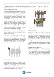
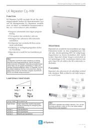
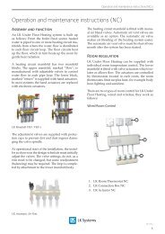
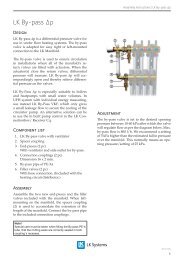
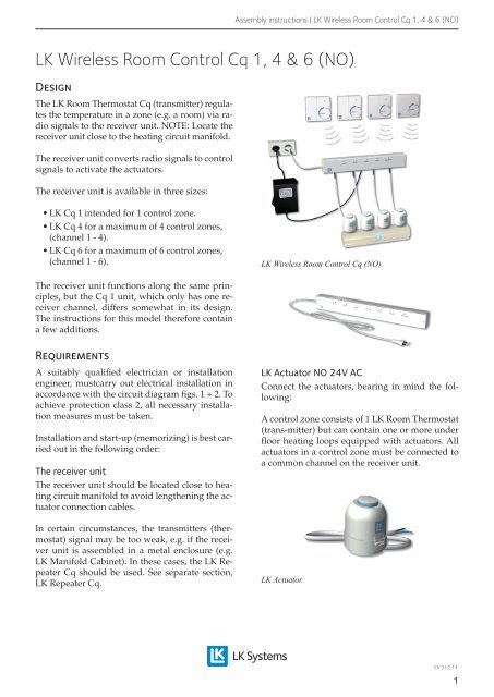
Assembly instructions | <strong>LK</strong> <strong>Wireless</strong> <strong>Room</strong> <strong>Control</strong> <strong>Cq</strong> 1, 4 & 6 (NO)<strong>LK</strong> <strong>Wireless</strong> <strong>Room</strong> <strong>Control</strong> <strong>Cq</strong> 1, 4 & 6 (NO)DesignThe <strong>LK</strong> <strong>Room</strong> Thermostat <strong>Cq</strong> (transmitter) regulatesthe temperature in a zone (e.g. a room) via radiosignals to the receiver unit. NOTE: Locate thereceiver unit close to the heating circuit manifold.The receiver unit converts radio signals to controlsignals to activate the actuators.The receiver unit is available in three sizes:• <strong>LK</strong> <strong>Cq</strong> 1 intended for 1 control zone.• <strong>LK</strong> <strong>Cq</strong> 4 for a maximum of 4 control zones,(channel 1 - 4).• <strong>LK</strong> <strong>Cq</strong> 6 for a maximum of 6 control zones,(channel 1 - 6).<strong>LK</strong> <strong>Wireless</strong> <strong>Room</strong> <strong>Control</strong> <strong>Cq</strong> (NO).The receiver unit functions along the same principles,but the <strong>Cq</strong> 1 unit, which only has one receiverchannel, differs somewhat in its design.The instructions for this model therefore containa few additions.RequirementsA suitably qualified electrician or installationengineer, mustcarry out electrical installation inaccordance with the circuit diagram figs. 1 + 2. Toachieve protection class 2, all necessary installationmeasures must be taken.Installation and start-up (memorizing) is best carriedout in the following order:The receiver unitThe receiver unit should be located close to heatingcircuit manifold to avoid lengthening the actuatorconnection cables.In certain circumstances, the transmitters (thermostat)signal may be too weak, e.g. if the receiverunit is assembled in a metal enclosure (e.g.<strong>LK</strong> Manifold Cabinet). In these cases, the <strong>LK</strong> Repeater<strong>Cq</strong> should be used. See separate section,<strong>LK</strong> Repeater <strong>Cq</strong>.<strong>LK</strong> Actuator NO 24V ACConnect the actuators, bearing in mind the following:A control zone consists of 1 <strong>LK</strong> <strong>Room</strong> Thermostat(trans-mitter) but can contain one or more underfloor heating loops equipped with actuators. Allactuators in a control zone must be connected toa common channel on the receiver unit.<strong>LK</strong> Actuator.<strong>EN.33.C.14</strong>.1
Assembly instructions | <strong>LK</strong> <strong>Wireless</strong> <strong>Room</strong> <strong>Control</strong> <strong>Cq</strong> 1, 4 & 6 (NO)<strong>Cq</strong> 4 and <strong>Cq</strong> 6 <strong>Control</strong> UnitFor the <strong>Cq</strong> 4 and <strong>Cq</strong> 6 Receiver Unit, a maximumof 4 actuators can be connected to each channel.The circuit diagram shows that all channels in <strong>Cq</strong>4, and 2 channels in <strong>Cq</strong> 6, have double terminalboards, a or c respectively, for connecting the actuators.<strong>Cq</strong>4 and <strong>Cq</strong>6 receiver units can operate amaximum of 16 actuators.When connecting two or more actuators to thesame channel, the connections must be only tothe double circuit boards.channel 1 channel 2 channel 3 channel 4Supply AC 24V<strong>LK</strong> TransformerMMains AC 230V29NCircuit diagram <strong>Cq</strong> 1, (M = Actuator).<strong>LK</strong> Transformer 230/24 V ACA transformer 60 VA for 24V AC supply is connectedin accordance with the circuit diagram foreach receiver unit.MainsAC 230VSupply AC 24V<strong>LK</strong> TransformerCircuit diagram <strong>Cq</strong> 4, (M = actuator).channel 1 channel 2 channel 3 channel 4 channel 5 channel 6MainsAC 230VSupply AC 24V<strong>LK</strong> TransformerCircuit diagram <strong>Cq</strong> 6, (M = actuator).<strong>Cq</strong> 1 Receiver Unit<strong>Cq</strong> 1 Receiver Unit differs from the other units asup to eight actuators can be connected.230V mains voltage connection• Connect the receiver unit and the transformerto the mains.• Check the primary and secondary voltage.• Reassemble the protection box on the receiverunit before Memorizing/Start-up.Up to two actuators can be connected direct to<strong>Cq</strong>1. However, if necessary, it is possible to connectup to eight actuators to <strong>Cq</strong>1 by using an externalwiring/junction box. In both cases the actuatorsare connected parrallel to each other andin line between terminal 9 and the <strong>LK</strong> Transformer.<strong>EN.33.C.14</strong>.2
Assembly instructions | <strong>LK</strong> <strong>Wireless</strong> <strong>Room</strong> <strong>Control</strong> <strong>Cq</strong> 1, 4 & 6 (NO)Memorizing/activation - Start-upResetAlways begin memorizing by first erasing all previousprogramming.For <strong>Cq</strong> 4 and <strong>Cq</strong> 6 as follows:• Press the ”Reset” button and the button for”Channel 1” at the same time.• First release the ”Reset” button, followed bythe ”Channel 1” button.For <strong>Cq</strong> 1 as follows:• Press the ”Reset” button and the button !at the same time.• First release the ”Reset” button, followed bythe button ! .• Press ”Reset” again.<strong>LK</strong> <strong>Room</strong> Thermostat <strong>Cq</strong>Open the door on the room thermostat and removethe transport protection covering the batteries.DCACheck the mains switch (A) is in the lower positiontowards the heat symbol as shown in thepicture. During memorizing, the thermostat willattempt to communicate with the activated channelon the receiver unit. Memorizing can takeplace before the thermostat is assembled in theintended place. The distance between the thermostatand the receiver should be at least 2 metresduring memorizing.NOTE!Mark the thermostat with the channel number that it willbe sent to. (e.g. with tape on the inside of the door.)Activating the receiverFor <strong>Cq</strong> 4 and <strong>Cq</strong> 6 as follows:• To activate the memorizing phase on thereceiver unit, press the button for the channelthat is to be activated first. A weak soundsignal is heard and the indicator light willcome on.For <strong>Cq</strong> 1 as follows:• To activate the memorizing phase on thereceiver unit, press the button ! . A weaksound signal is heard and the indicator lightwill come on.Activating the room thermostat• Press and hold the lower black button (B).• Briefly press the upper black button (C).• When the indicator light (D) is lit, release thelower button. Memorizing (the connection)between the thermostat and the channelselected now occur. Pay attention to the receiver.Once contact is established, the soundsignal will cease and the indicator light willgo out.• Press the upper button on the room thermostatone more time to switch off the indicatorlight. (The indicator light on the thermostatin future use is only used to warn of low batterypower.)B<strong>EN.33.C.14</strong>.3
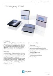
Assembly instructions | <strong>LK</strong> <strong>Wireless</strong> <strong>Room</strong> <strong>Control</strong> <strong>Cq</strong> 1, 4 & 6 (NO)Function controlPlace the room thermostat in the room where itis intended to be assembled according to the design.By turning the thermostat’s adjustment dial,the indicator light on the receiver’s channel willbe lit or switched off respectively within approximately30 seconds.• Dial towards maximum temperature, thelight on the receiver unit comes on.• Dial towards minimum temperature, thelight on the receiver unit goes off.NOTE: The receiver <strong>Cq</strong> 1 works the opposite way.If the light switches off when it should come on,check that the mains switch’s setting is in the lowerposition towards the heat symbol. See thesection <strong>LK</strong> <strong>Room</strong> Thermostat <strong>Cq</strong>. If the settingwas right and the problem continues, see the section”Heat/Cool”.• Mount it approximately 1.5 metres above thefloor.• Do not mount it near a radio, TV or othertransmitter.• Do not mount it near metal objects, such asmetal doors, metal cupboards or similar.NOTE:After fixing to the wall, care must be taken to ensurebuttons A, B & C are correctly located in the front cover;misalignment will cause malfunctions.Completing activation / memorizingContinue activation / memorizing in the sameway as for the other channels, following the instructionsfor the <strong>LK</strong> <strong>Room</strong> Thermostat <strong>Cq</strong>.<strong>LK</strong> Repeater <strong>Cq</strong>NOTE:During set up (only) the indicator light on channel 4 orchannel 6 comes on when one or more other channelstrigger the heating. This function continues until all thechannels are activated. For more information, see thesection “Pump <strong>Control</strong>”.Additional measuresAssembling the room thermostatOpen the room thermostat by pulling the temperaturescale dial right out and loosening the screwthat becomes visible. Bend out the upper part tothe left until it becomes loose. Position the roomthermostat as per the design plan.For the room thermostat to function properly, thefollowing guidance should be followed:The <strong>LK</strong> Repeater <strong>Cq</strong> is used to increase the transmittingdistance between <strong>LK</strong> <strong>Room</strong> Thermostat<strong>Cq</strong> and <strong>LK</strong> Receiving Unit <strong>Cq</strong>. The Repeater isalso used when it may be necessary to improvethe quality of transmission, e.g. when affected byexternal sources of interference. Place the repeaterin an earthed wall socket. The socket in the repeaterreplaces the occupied wall socket. The repeaterwill function automatically. The user doesnot have to do anything to add the apparatus tothe existing radio links. The repeater should belocated at an appropriate distance from the transmitter.For more information, see seperate instructionfor <strong>LK</strong> Repeater <strong>Cq</strong>.• Mount it on an inner wall where it is ventilatedbut not in a draught. (NOTE FOR UK:in some home refurbishment projects wherethe building is poorly insulated, it may beprudent to place the thermostat on an outside,or coldest, wall. The thermostat will thencompensate by calling for heat.)• Do not expose it to direct sunlight or otherheat sources.<strong>EN.33.C.14</strong>.4
Assembly instructions | <strong>LK</strong> <strong>Wireless</strong> <strong>Room</strong> <strong>Control</strong> <strong>Cq</strong> 1, 4 & 6 (NO)Pump control for <strong>Cq</strong> 4 and <strong>Cq</strong> 6The last channels on the receiver <strong>Cq</strong> 4 (channel 4)and <strong>Cq</strong> 6 (channel 6) can start or stop a circulatingpump. However, <strong>Cq</strong> 4 becomes 3 channeland <strong>Cq</strong> 6, 5 channel receiver. Pump control can bearranged via an external relay for 24/230 V (relaynot supplied by <strong>LK</strong>). The 24 V side of the relayshould be connected to terminals A and C of thechannels. The channels have a time delay of 10minutes for pump control.Range control of radio signalTo determine a connection’s maximum range,the following check can be carried out:• First, carry out activation/memorizing bypressing and holding the lower black button(B), and briefly pressing the upper black button(C). The indicator light should now be lit.• Then push the “Reset” button on the receiverunit at the same time as the button for“Channel 2”.• First release “Reset” followed by the “Channel2” button. The sound signal and theindicator light will now pulse for about 2seconds on, 8 seconds off.• Next move the room thermostat far enoughaway from the receiver unit that the pulsesalmost stop. This is the maximum distancefor radio connection.• Finish the check by pressing “Reset” on thereceiver unit.The room thermostat returns to normal operationmode after a short time. Other channels are notaffected by the check. If the connection is insufficient,the radio signal can be strengthened with<strong>LK</strong> Repeater <strong>Cq</strong>. See separate section, <strong>LK</strong> Repeater<strong>Cq</strong>.Heating & coolingThe equipment is constructed so that it can beused to heat (under floor heating) and cool. Thefunctions are changed manually. When supplied,the components are set for heat. Switching to coolcan be done in two ways.Alternative 2Changing the whole installation by reprogrammingthe receiver unit as follows:Change to cool (summer operation):• Press the “Reset” button and the button for”Channel 3” at the same time.• First release “Reset” followed by “Channel3”.Change to heat (winter operation):• Press the “Reset” button and the button for”Channel 4” at the same time.• First release “Reset” followed by ”Channel4”.NOTE:For the <strong>Cq</strong> 1 unit, the change is made on the room thermostat.AlarmWhen a fault occurs, the indicator light begins toflash with an irregular time interval and a soundsignal is heard. During signal disruption, the affectedchannel will deliver approximately 70%heat output.Temporary interruptionIf no signal is received from the room thermostat(transmitter) for a period between 1 to 10 hours,the indicator light on the receiver unit will displayshort flashes, but no sound signal. Acknowledgmentof the alarm occurs automatically if thetransmitter signal reoccurs.Prolonged interruptionIf no signal is received from the room thermostat(transmitter) for a period of more than 10 hours,the indicator light on the receiver unit will displayshort flashes and a sound signal is emitted.Acknowledgment of the alarm occurs automaticallyif the transmitter signal is regained. In theevent of a loss of power in the receiver unit, noprogramming will be affected. Operation willcontinue as normal once power is restored.Alternative 1Change all room thermostats by moving themains switch A to the upper position.<strong>EN.33.C.14</strong>.5
Assembly instructions | <strong>LK</strong> <strong>Wireless</strong> <strong>Room</strong> <strong>Control</strong> <strong>Cq</strong> 1, 4 & 6 (NO)Acknowledgment of the alarmTo acknowledge a disruption, interrupt “Memorizing”,orend a connection test, press “Reset” onthe receiver unit.The output will return to the basicposition. When the next control signal comesafter approximately 10 - 20 minutes, the outputwill return to its correct position. Any radio connectionestablished will not be affected.Valve exercisingThe actuator disconnects once a day for 3 minutesand opens the valve on the heating circuitdistributor. This function prevents valves fromsticking, for instance, during the summer period.If valve exercising is not required, this functioncan be disconnected using vertical 1 in the roomthermometer. Remove the temperature dial, loosenthe screw and lift the cover. Remove vertical1, which is marked with BR1 on the printed circuitcard.Description of functions - room thermostat<strong>Control</strong> occurs using pulse width modulation(PBM), which is intended for actuators. The controlsignal, which is calculated from the differencebetween the actual temperature and the temperatureentered, is emitted in the form of a signalwith different pulse and rest ratios. The sum ofthe signal and rest period is always 10 minutes.With large temperature variations, the thermostatis constantly switching on or off.Changing the batteries on the room thermostatWhen the indicator light fl ashes with 15-secondintervals, the batteries should be changed withina few days. The batteries are located under thebattery cover. For information about battery type,see “Technical data.”Connection checkAfter using the receiver unit’s “Reset” function,the respective channel’s indicator light will indicate,by a shortflash, that the connection has beenestablished.Technical data for receiver<strong>Cq</strong>1, <strong>Cq</strong>4 & <strong>Cq</strong>6Supply voltageAC 230 V + 24 V, 50/60 HZPower requirement Approx. 3 VA for <strong>Cq</strong> 4 - 6Approx. 12 VA for <strong>Cq</strong> 1Operating temperature 0 - +50 °CStorage temperature -20 - +60 °CDisconnecting sound signal Vertical BR1 for <strong>Cq</strong> 4 - 6Vertical J2 for <strong>Cq</strong> 1AerialInternalReception frequency 868 MHzProtection mode IP 40Protection class 2Output signal, type Relay, 1 alternating potentialfreeAC 24 V - 230 V for<strong>Cq</strong> 4 - 6AC 24 V - 230 V for<strong>Cq</strong> 1Number of actuators AC24 V 2-3 VA NO/NC, whichcan be controlled per relayoutputMaximum number of actuatorswithin same receiverunitMax 8 A cos φ = 1Max 2 A cos φ = 0,6Max 16 A cos φ = 1Max 2 A cos φ = 0,6For <strong>Cq</strong> 4 - 6 = 4For <strong>Cq</strong> 1 = 8NOTE:Trouble free operation cannot always be guaranteed dueto possible external interference sources.16After changing the batteries, the thermostat willcontinue to operate according to the chosen modeof operation. With depleted batteries, the receiverchannel will continuously deliver 70% heat output.<strong>EN.33.C.14</strong>.6
Assembly instructions | <strong>LK</strong> <strong>Wireless</strong> <strong>Room</strong> <strong>Control</strong> <strong>Cq</strong> 1, 4 & 6 (NO)Technical data for transmitterType designationSetting range +5 - +30 °C<strong>LK</strong> <strong>Room</strong> Thermostat <strong>Cq</strong>Supply voltage 2 x 1.5V batteries = 3V,alkaline (LR03)Battery lifeApproximately 3 years<strong>Control</strong> functionPBM (optional 2 point)Cycle timeApproximately 10 minutes(total on and off time)Measurement interval Approximately 10 minutesTypeHeat/CoolValve exercisingOnce a day for 3 minutes(can be switched off, BR1)Temperature sensor NTCTransfer frequency 868 MHzModulationFMAerialInternTransmission interval < 10 minutesRange (typical) 100 metres free air or 2floors or 3 wallsProtection mode IP 40Protection class 2Operating temperature -25 - +40 °CStorage temperature -25 - +70 °CTemperature limitOn the adjustment dial4607527,1<strong>LK</strong> <strong>Room</strong> Thermostat <strong>Cq</strong>.71 26,8460Measurements<strong>LK</strong> Receiver Unit <strong>Cq</strong> 1.2,250,2404,362,53722472,557<strong>LK</strong> Receiver Unit <strong>Cq</strong> 4.2,250,2404,397,54522522,557<strong>LK</strong> Receiver Unit <strong>Cq</strong> 6.<strong>EN.33.C.14</strong>.7