A general, accurate procedure for calculating molecular interaction ...
A general, accurate procedure for calculating molecular interaction ...
A general, accurate procedure for calculating molecular interaction ...
- No tags were found...

Create successful ePaper yourself
Turn your PDF publications into a flip-book with our unique Google optimized e-Paper software.
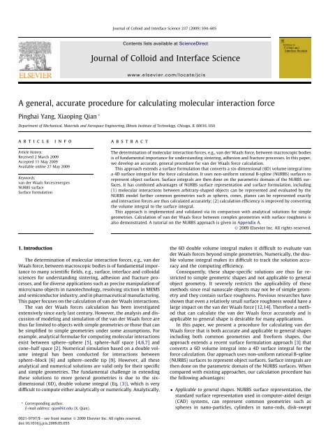
Journal of Colloid and Interface Science 337 (2009) 594–605Contents lists available at ScienceDirectJournal of Colloid and Interface Sciencewww.elsevier.com/locate/jcisA <strong>general</strong>, <strong>accurate</strong> <strong>procedure</strong> <strong>for</strong> <strong>calculating</strong> <strong>molecular</strong> <strong>interaction</strong> <strong>for</strong>cePinghai Yang, Xiaoping Qian *Department of Mechanical, Materials and Aerospace Engineering, Illinois Institute of Technology, Chicago, IL 60616, USAarticleinfoabstractArticle history:Received 2 March 2009Accepted 11 May 2009Available online 27 May 2009Keywords:van der Waals <strong>for</strong>ces/energiesNURBS surfaceSurface <strong>for</strong>mulationThe determination of <strong>molecular</strong> <strong>interaction</strong> <strong>for</strong>ces, e.g., van der Waals <strong>for</strong>ce, between macroscopic bodiesis of fundamental importance <strong>for</strong> understanding sintering, adhesion and fracture processes. In this paper,we develop an <strong>accurate</strong>, <strong>general</strong> <strong>procedure</strong> <strong>for</strong> van der Waals <strong>for</strong>ce calculation.This approach extends a surface <strong>for</strong>mulation that converts a six-dimensional (6D) volume integral intoa 4D surface integral <strong>for</strong> the <strong>for</strong>ce calculation. It uses non-uni<strong>for</strong>m rational B-spline (NURBS) surfaces torepresent object surfaces. Surface integrals are then done on the parametric domain of the NURBS surfaces.It has combined advantages of NURBS surface representation and surface <strong>for</strong>mulation, including(1) <strong>molecular</strong> <strong>interaction</strong>s between arbitrary-shaped objects can be represented and evaluated by theNURBS model further common geometries such as spheres, cones, planes can be represented exactlyand <strong>interaction</strong> <strong>for</strong>ces are thus calculated <strong>accurate</strong>ly; (2) calculation efficiency is improved by convertingthe volume integral to the surface integral.This approach is implemented and validated via its comparison with analytical solutions <strong>for</strong> simplegeometries. Calculation of van der Waals <strong>for</strong>ce between complex geometries with surface roughness isalso demonstrated. A tutorial on the NURBS approach is given in Appendix A.Ó 2009 Elsevier Inc. All rights reserved.1. IntroductionThe determination of <strong>molecular</strong> <strong>interaction</strong> <strong>for</strong>ces, e.g., van derWaals <strong>for</strong>ce, between macroscopic bodies is of fundamental importanceto many scientific fields, e.g., surface, interface and colloidalsciences <strong>for</strong> understanding sintering, adhesion and fracture processes,and <strong>for</strong> diverse applications such as precise manipulation ofmicro/nano objects in nanotechnology, resolving stiction in MEMSand semiconductor industry, and in pharmaceutical manufacturing.This paper focuses on the calculation of van der Waals <strong>interaction</strong>s.The van der Waals <strong>for</strong>ces calculation has been investigatedextensively since early last century. However, the analysis and discussionof modeling and simulation of the van der Waals <strong>for</strong>ce arethus far limited to objects with simple geometries or those that canbe simplified to simple geometries under some assumptions. Forexample, analytical <strong>for</strong>mulae <strong>for</strong> computing <strong>molecular</strong> <strong>interaction</strong>sexist between sphere–sphere [5], sphere–half space [4,6,7] andcone–half space [2]. Numerical simulation based on a double volumeintegral has been conducted <strong>for</strong> <strong>interaction</strong>s betweensphere–block [6] and sphere–needle tip [9]. However, all theseanalytical and numerical solutions are valid only <strong>for</strong> their specificand simple geometries. The fundamental challenge in extendingthese solutions to more <strong>general</strong> geometries is due to the sixdimensional(6D), double volume integral (Eq. (3)), which is verydifficult to compute either analytically or numerically. Analytically,* Corresponding author.E-mail address: qian@iit.edu (X. Qian).the 6D double volume integral makes it difficult to evaluate vander Waals <strong>for</strong>ces beyond simple geometries. Numerically, the doublevolume integral makes its difficult to track the solution accuracyand the computing efficiency.Consequently, these shape-specific solutions are thus far restrictedto simple geometric shapes and not applicable to <strong>general</strong>object geometry. It severely restricts the applicability of thesemethods since real nanoscale objects may not be of simple geometryand they contain surface roughness. Previous researches haveshown that even a relatively small surface roughness would have alarge impact on the van der Waals <strong>for</strong>ce [12,14]. There<strong>for</strong>e a methodthat can calculate the van der Waals <strong>for</strong>ce <strong>accurate</strong>ly and isapplicable to <strong>general</strong> shape is desirable <strong>for</strong> many applications.In this paper, we present a <strong>procedure</strong> <strong>for</strong> <strong>calculating</strong> van derWaals <strong>for</strong>ce that is both <strong>accurate</strong> and applicable to <strong>general</strong> shapesincluding both common geometries and free<strong>for</strong>m shapes. Ourapproach extends a recent surface <strong>for</strong>mulation approach [3] thatconverts a 6D volume integral into a 4D surface integral <strong>for</strong> the<strong>for</strong>ce calculation. Our approach uses non-uni<strong>for</strong>m rational B-spline(NURBS) surfaces to represent object surfaces. Surface integrals arethen done on the parametric domain of the NURBS surfaces. Whencompared with existing approaches, our calculation <strong>procedure</strong> hasthe following advantages: Applicable to <strong>general</strong> shapes. NURBS surface representation, thestandard surface representation used in computer-aided design(CAD) systems, can represent common geometries such asspheres in nano-particles, cylinders in nano-rods, disk-swept0021-9797/$ - see front matter Ó 2009 Elsevier Inc. All rights reserved.doi:10.1016/j.jcis.2009.05.055
P. Yang, X. Qian / Journal of Colloid and Interface Science 337 (2009) 594–605 595NomenclatureACq iw vdwEfHamaker constantLondon–van der Waals constantatomic density of body ienergy potential between two atoms/moleculesvan der Waals energy between an atom/molecule and abodyvan der Waals <strong>for</strong>ce between two atoms/moleculesF/FsSp i,jw i,jU,Vnvan der Waals <strong>for</strong>ce between two bodiesdistance between the two atoms/moleculesNURBS surfacecontrol points of NURBS surfacesweights of NURBS surfacesknot vectors of NURBS surfacessurface normalshape in nano-wires, and other shapes such as cone, torus, ellipsoid,and plane exactly. It can also conveniently represent free<strong>for</strong>mgeometry e.g., objects with surface roughness. High accuracy. Since <strong>molecular</strong> <strong>interaction</strong>s fall off rapidly (at arate of inverse power of six) over the separation distance, anysmall discrepancy between Gaussian quadrature points used inthe surface integration and the underling surface would leadto a significant bias in the resulting <strong>for</strong>ce. NURBS surfaces canrepresent common geometry exactly and the Gaussian quadraturepoints used in our surface integration lie exactly on the surface,i.e., without any geometric approximation error. NURBSsurfaces can also be subdivided to produce more Gaussian quadraturepoints lying exactly on the surface to further improve theaccuracy of the numerical integration. Our approach thus leadsto far better accuracy than those based on the approximatedgeometry e.g., in mesh based approach [13]. Computing efficiency. Due to the use of 4D surface integrationinstead of 6D volume integration, the calculation efficiency hasbeen improved.Fig. 1 compares the proposed NURBS surface based approachwith the analytical solution to van der Waals <strong>for</strong>ce calculationwhere the first and second numerical simulations refer to the calculation<strong>for</strong> the patches be<strong>for</strong>e and after the subdivisions. It showsNURBS surface based approach, with patch refinement, produces<strong>accurate</strong> results. For details of this sphere–sphere <strong>interaction</strong> <strong>for</strong>cecalculation, please refer to Section 5.1.2.The remainder of the paper is organized as follows. Section 2briefly introduces the van der Waals <strong>for</strong>ce calculation. In Section 3,we introduce the NURBS surface as our underlying representationof 3D object surfaces and discuss its salient features, which are beneficial<strong>for</strong> the van der Waals <strong>for</strong>ce calculation. In Section 4, weexplain our van der Waals <strong>for</strong>ce calculation approach in details,which is based on the NURBS surface <strong>for</strong>mulation. In Section 5, wepresent experimental examples to illustrate the accuracy and <strong>general</strong>applicability of this approach. In Section 6, we discuss its comparisonwith the triangular mesh based approach and the use ofadaptive NURBS surface subdivision, and its error estimation andconvergence analysis. We conclude this paper in Section 7.2. van der Waals <strong>for</strong>ce computingvan der Waals <strong>for</strong>ce is an inter<strong>molecular</strong> <strong>for</strong>ce that arises from afluctuating electromagnetic field resulting in instantaneous (electricaland magnetic) polarizations between atoms/molecules. vander Waals <strong>for</strong>ce has been studied extensively [8,10]. Here, webriefly present some basic concepts and <strong>for</strong>mulas, upon whichwe have developed the NURBS surface based approach <strong>for</strong> vander Waals <strong>for</strong>ce computing.The London equation is the first basic equation used to calculatethe energy potential, w vdw , between two atoms/molecules:w vdw ðsÞ ¼ C s 6 ð1Þwhere s is the distance between the two atoms/molecules and C isthe London–van der Waals constant, a material-dependant <strong>interaction</strong>constant between the two atoms/molecules. To account <strong>for</strong> theretardation effect, a corrected London equation is introduced [1]:Cw vdw ðsÞ ¼s 6 ðs þ cÞwhere is c a constant value proportional to the ‘‘characteristicwavelength” of the <strong>interaction</strong>.In order to validate our numerical simulation result with existinganalytical solutions, we focus on calculation based on the originalLondon equation, i.e., Eq. (1), <strong>for</strong> computing atoms/moleculesenergy potential since currently analytical solutions only exist <strong>for</strong>the original London equation. However, our NURBS surface basedapproach is applicable to both equations since both can be directlynumerically evaluated with the Gaussian quadrature method.Based on Eq. (1), the van der Waals <strong>for</strong>ce f between the twoatoms/molecules is then given by:f ¼ rw vdw ð2ÞAssuming that the two bodies have the properties of additivity, uni<strong>for</strong>mmaterial properties and continuous medium, the <strong>for</strong>cebetween two bodies of arbitrary geometry is:Z ZF ¼ q 1q 2fðsÞdV 1 dV 2 ;ð3ÞV 1V 2where q i , i = 1, 2 is the atomic density of body i. Eq. (3) can berewritten as:Z ZZ ZF ¼ C q 1q 2rw vdw dV 1 dV 2 ¼ C q 1q 2r 1V 2 V 1 V 2 V 1s dV 1dV 6 2 ð4ÞSimilarly, the energy of van der Waals <strong>interaction</strong> between an atom/molecule and an arbitrarily shaped body is given byZZ1E ¼ C q 1w vdw dV 1 ¼ C q 1V 1 V 1s dV 6 1ð5ÞIn Eq. (4), a double volume integral is involved, which is very difficultto execute either analytically or numerically.In this paper, to reduce the computational complexity, we extendthe surface <strong>for</strong>mulation [3] to objects described by NURBSsurfaces. This surface <strong>for</strong>mulation reduces the 6D integral to 4Dintegral. The NURBS surface also eliminates the geometric approximationused in other surface <strong>for</strong>mulation based schemes [13]. Inthe next two sections, we briefly introduce NURBS surfaces andthen present our NURBS surface based van der Waals <strong>for</strong>ce computingapproach.3. NURBS surface representation <strong>for</strong> 3D objectsIn this paper, NURBS representation is used to represent geometriesof nanoscale objects and compute the van der Waals <strong>for</strong>ces/energies. We give a brief overview of NURBS surface and details arecommonly available in computer-aided design (CAD) andcomputer graphics literature such as [11].
596 P. Yang, X. Qian / Journal of Colloid and Interface Science 337 (2009) 594–605Fig. 1. NURBS representation based surface <strong>for</strong>mulation <strong>for</strong> van der Waals <strong>for</strong>ce calculation: (a) NURBS representation of a sphere; (b) subdivided NURBS patches; (c)comparison of analytical solution with the numerical results; (d) relative error.By means of tensor products, a NURBS surface can be constructedfrom a bidirectional net of (n +1) (m + 1) control pointsand knot vectors {u i } and {v i }:P n P mi¼0 j¼0Sðu; vÞ ¼N i;pðuÞN j;q ðvÞw i;j p i;jP n mi¼0Pj¼0 N ð6Þi;pðuÞN j;q ðvÞw i;jThen we can obtain a bi-variate surface over the two independentparameters u and v, where p i,j represent control points of the NURBSsurface, w i,j are the weights and N i,p (u) and N j,q (v) are the pth degreeand qth degree B-spline basis functions defined in u and v directions,respectively. Basis function N i,p (u) is defined as:N i;0 ðuÞ ¼ 1 if u i 6 u 6 u iþ1ð7Þ0 otherwiseN i;p ðuÞ ¼ u u iN i;p 1 ðuÞþ u iþpþ1 uN iþ1;p 1 ðuÞ ð8Þu iþp u i u iþpþ1 u iþ1where U ={u 0 ,u 1 ,...,u n+p+1 } is the knot vector in u direction.Similarly, basis function N j,q (v) is defined as:N j;0 ðvÞ ¼ 1 if v j 6 v 6 v jþ10 otherwiseð9ÞN j;q ðvÞ ¼ v v jN j;q 1 ðvÞþ v jþqþ1 vN jþ1;q 1 ðvÞv jþp v j v jþqþ1 v jþ1ð10Þwhere V ={v 0 ,v 1 ,...,v m+q+1 } is the knot vector in v direction.Two NURBS surfaces, one spherical particle and the other a free<strong>for</strong>msurface, are illustrated in Fig. 2. The black curves on the surfaceare the knot curves and the yellow dots and lines represent thecontrol points and the control polygon.NURBS surface representation has many desirable properties[11]. We highlight below some of them that are relevant to this work.Property 1. It offers one common mathematical expression <strong>for</strong> bothcommon shapes (e.g., plane, sphere, cylinder and cone) and free<strong>for</strong>mshapes.For example, a unit sphere, with a center located at the origin, isrepresented by a bi-quadratic NURBS surface as shown in Fig. 2a.Table 1 gives all the necessary parameters to create this NURBSFig. 2. Examples <strong>for</strong> NURBS surfaces. (a) A unit sphere; (b) a smooth free<strong>for</strong>m surface.
P. Yang, X. Qian / Journal of Colloid and Interface Science 337 (2009) 594–605 597Table 1NURBS surface parameters <strong>for</strong> the unit sphere.Surface type Degree Knot vector Control points p i,j Weights w i,ju v u vSphere 2 2 {0, 0, 0, 0.25, 0.25, 0.5,0.5, 0.75, 0.75, 1, 1, 1}{0, 0, 0, 0.5,0.5, 1, 1, 1}p 0,j = p 8,j = (1,0,j 2) w i,j =1,i =0,2,4,6,8, j =0,2,4p i,0 = (0,0, 1), p i,3 = (0,0,1) w i;j ¼ pffiffi22 ; i ¼ 0; 2; 4; 6; 8; j ¼ 1; 3p 1,j = (1,1,j 2), p 2,j = (0,1,j 2) w i;j ¼ pffiffi22 ; i ¼ 2; 4; 6; 8; j ¼ 1; 3; 5p 3,j =( 1,1,j 2), p 4,j =( 1,0,j 2) w i;j ¼ 1 2 ; i ¼ 2; 4; 6; 8; j ¼ 2; 4p 5,j =( 1, 1,j 2), p 6,j = (0, 1,j 2)p 7,j = (1, 1,j 2), i =0...8, j = 1,2,3sphere, i.e., degrees in u/v direction, 12/8 knots in u/v direction and9 5 control points and weights. All the NURBS spheres used inthis paper can be generated based on the data in Table 1 and theNURBS surface subdivision technique.Property 2. It is enclosed within the convex hull of its control polygon.By applying this property, we can obtain the distance boundbetween two NURBS surfaces, which can be useful <strong>for</strong> identifyingthe error bound in van der Waals <strong>for</strong>ce/energy calculation andmay enable the development of an adaptive surface subdivisionscheme as discussed in Section 6.2.Property 3. It is a piecewise surface composed of surface patchesdefined on each knot span.This means that an NURBS surface can be divided into severalNURBS patches, which are defined as NURBS surfaces withoutinner knots. And the NURBS patch is the basic unit <strong>for</strong> van derWaals <strong>for</strong>ce/energy calculation in this paper. For example, theNURBS surface shown in Fig. 2b can be divided into 3 3 NURBSpatches by the four black, inner knot curves.4. NURBS based surface <strong>for</strong>mulation <strong>for</strong> van der Waals <strong>for</strong>cecalculationIn Eq. (2), the <strong>interaction</strong> <strong>for</strong>ce between two atoms/molecules isdefined as the gradient of the <strong>interaction</strong> potential in terms of thedistance s. Now, we further define a vector field G based on thepotential fieldr G ¼ w vdw ð11ÞSubstitution of Eqs. (2) and (11) into Eq. (3) gives a new <strong>for</strong>mula <strong>for</strong>the van der Waals <strong>for</strong>ce between two arbitrary-shaped bodies:Z ZF ¼ q 1q 2rðr GÞdV 1 dV 2 :ð12ÞV 1V 2Applying the divergence theorem, we obtainZF ¼ q 1q 2ZS 2S 1ðG n 1 Þn 2 dS 1 dS 2ð13Þwhere n 1 and n 2 represent the outward unit normal field of thenano-bodies 1 and 2, S 1 and S 2 represent the boundary surfaces ofthe nano-bodies 1 and 2, which are NURBS surfaces oriented by outward-pointingnormals.From NURBS surface Property 3, we easily see that these twoNURBS surfaces S 1 and S 2 are piecewise surfaces with (n 1 p 1 ) (m 1 q 1 ) and (n 2 p 2 ) (m 2 q 2 ) component NURBS patches,respectively, where n i and m i represent the number of control pointsin u and v direction, p i and q i represent the degree of the basis functionsin u and v direction. Hence, Eq. (13) can be rewritten as:n X1 p 1 X X XF ¼ q 1q 2i 1 ¼1m 1 q 1 n 2 p 2 m 2 q 2Z ZS i2 j 2j 1 ¼1i 2 ¼1j 2 ¼1S i1 j 1ðG n i1 j 1Þn i2 j 2dS i1 j 1dS i2 j 2ð14ÞIn other words, the total <strong>interaction</strong> <strong>for</strong>ce between the two NURBSsurfaces S 1 and S 2 can be obtained by summarizing <strong>interaction</strong><strong>for</strong>ces between all component NURBS patch pairs, i.e., S i1 j 1and S i2 j 2. Hence, the initial problem is reduced to sub-problems ofcomputing <strong>interaction</strong> <strong>for</strong>ces between NURBS patch pairs. Let Sand S denote an arbitrary NURBS patch of surface S 1 and S 2 , respectively.Similar to Eq. (14), we have the <strong>interaction</strong> <strong>for</strong>ce between Sand S isZ ZeF ¼ q 1q 2ðG nÞn dSdS:SSFrom the definition of surface integral, we further haveZ umax Z vmax Z umax Z vmax@SeF ¼ q 1q 2ðG nÞu min v min u min v min@u @S @v dudv n@S@u @S @v dudv;ð15Þ where ½u minu max Š ½v minv max Š and u minu max vmin v maxrepresent the parametric domains of surfaces S and S, respectively,the expression between vertical bars on the right-hand side is themagnitude of the cross product of the partial derivatives of S andS, as shown in Fig. 3. Thus, there are only three terms in Eq. (15) thatneed to be further expanded, i.e., G, n and n. However, we knowthat n and n are the unit normals of S and S shown in Fig. 3. Notethat, <strong>for</strong> any parametric surface S defined as a function of parameterpair (u,v), a unit normal vector at any regular point of this surface isgiven asn ¼@S@u @S @S@v @u @S @v :ð16ÞMeanwhile, <strong>for</strong> this NURBS patch pair, the separation distance, s,from Eq. (1) can be written as:rffiffiffiffiffiffiffiffiffiffiffiffiffiffiffiffiffiffiffiffiffiffiffiffiffiffiffiffiffiffiffiffiffiffiffiffiffi s ¼ S S S Sð17ÞThis allows us to combine Eqs. (1) and (11) to obtain the solution <strong>for</strong>the function G: C S SG ¼ 3ð18Þ3 S S S SHence, substituting Eqs. (16) and (18) into Eq. (15), we obtain:eF ¼q 1q 2Z umaxu minZ vmaxv minZ umaxu min!@S@u @S dudvdudv@vZ vmax0B C ðS SÞ@ 3v min3 S S S S1!@S@u @S CA@vð19Þ
598 P. Yang, X. Qian / Journal of Colloid and Interface Science 337 (2009) 594–605vSv maxv minouminFinally, by summarizing the <strong>interaction</strong> <strong>for</strong>ce between each pairof NURBS patches, we can obtain the total <strong>interaction</strong> <strong>for</strong>cebetween the two NURBS surfaces S 1 and S 2 .The four-dimensional (4D) integral in Eq. (19) is still difficult <strong>for</strong>analytical evaluation. There<strong>for</strong>e, a numerical integration method,i.e., Gaussian quadrature method, is used to approximate such a4D integral. By implementing the Gaussian quadrature method, e Fcould be approximated aseF ¼ q 1q 2X n i¼1S( u , v )i jn( u i, v j)( ui, v j)ParametricDomainX m j¼1X n i¼1umaxX m j¼1wðu i ; v j Þ wðu i ; v j Þ ~ fðu i ; v j ; u i ; v j Þ ð20Þwhere n and m (respectively, n and m) represent the number of Gaussianquadrature points in u and v direction <strong>for</strong> surface S (respectively,S), ðu i ; v j Þ and ðu i ; v j Þ are the Gaussian quadrature points of surfaces Sand S; w and w are the corresponding weights. In this paper, we evaluatethe Gaussian quadrature points and corresponding weights bythe Legendre polynomials, which are defined in the interval of [ 1,1] and hence a changing of interval must be used be<strong>for</strong>e applyingthe Gaussian quadrature. And function ~ f is defined as01C Sðu;vÞ S u;v ~ Bfðu;v;u;vÞ¼ @ 3 Sðu;vÞ S u;v 3 Sðu;vÞ Sðu;vÞ!@Sðu;vÞ @Sðu;vÞ@u @vu@Sðu;vÞ @Sðu;vÞ@u @v!CAð21Þwhere Sðu; vÞ and Sðu; vÞ are the expressions <strong>for</strong> NURBS surfaces,which can be evaluated by Eq. (6) with given NURBS parameters.Similarly, <strong>for</strong> van der Waals energy between an atom/moleculeand any NURBS patch S of surface S 1 , we havesvv maxv minoS( u ,v )n( u , v )i jiu ,ParametricDomainuminj( )iv jumaxFig. 3. Graphical illustration of a pair of NURBS patches and the terms used in<strong>calculating</strong> their <strong>interaction</strong>.uSe E ¼ q1Z umaxu min!C ðS qÞv min 3ððS qÞðS qÞÞ @S3 @u @S dudv@vZ vmaxThis equation can be numerically evaluated asXe n X mC Sðu i ; v j Þ qE ¼ q1 wðu i ; v j Þ 3 i¼1 j¼1 3 Sðu i ; v j Þ q Sðu i ; v j Þ q@Sðu i ; v j Þ @Sðu i ; v j Þ!@u @vð22ÞSuch element <strong>interaction</strong> energies are then combined together as thetotal <strong>interaction</strong> energy between an atom/molecule and surface S 1 .5. ResultsIn this section, we validate our van der Waals <strong>for</strong>ce/energy calculationwith four experiments where the analytical solutions areavailable. We then extend our approach to calculate the ellipsoid/cube<strong>interaction</strong> <strong>for</strong>ce, which has no reported analytical solution.Finally, we finish this section with a more complex example,which involves a flared tip in Atomic Force Microscopes (AFM) anda rough surface containing hundreds of small features. Note, in allthese experiments, we adopt the physical constants from [6,7] <strong>for</strong>copper, i.e., atomic density q = 8.49 10 28 m -3 and London–vander Waals constant C = 4.5639 10 -78 Jm 6 .5.1. Validation of the proposed approachTo verify the validity of the van der Waals <strong>for</strong>ce/energy calculationapproach, we select four experiments: sphere–point vander Waals energy calculation, sphere–sphere, sphere–half spaceand cone–half space van der Waals <strong>for</strong>ce calculation, as shownin Fig. 4.5.1.1. Sphere/pointIt was shown in [6,7] that the van der Waals energy between asphere and a single molecule/atom q is determined by integratingvan der Waals energy (Eq. (1)) inside the volume of the sphere withrespect to the coordinates of q:E Sphere=Point ¼p C q12 ðd þ RÞ!2Rðd þ 2RÞ þ 2R3 d þ 1 13 ðd þ 2RÞ 2 d 2ð23Þwhere C is the London–van der Waals constant, q is the atomic densityof the sphere body, d is the closest separation between thesphere and the molecule/atom q and R is the radius of the sphere,as shown in Fig. 4a. From Eq. (23), we find that two geometricparameters, i.e., separation distance d and sphere radius R, arerequired <strong>for</strong> <strong>calculating</strong> the van der Waals energies <strong>for</strong> sphere–point<strong>interaction</strong>. In this experiment, the sphere radius is fixed asR = 100 nm, twenty different separation distance d are used to cal-Fig. 4. Geometric configurations <strong>for</strong> four experiments. (a) Sphere–point. (b) Sphere–sphere. (c) Sphere–half space. (d) Cone–half space.
P. Yang, X. Qian / Journal of Colloid and Interface Science 337 (2009) 594–605 599Fig. 5. Analytical and numerical results <strong>for</strong> sphere–point <strong>interaction</strong> energy calculation. In the first group of numerical simulation, the sphere has 32 bi-quadratic NURBSpatches; In the second group, the number of surface patches is refined to 128. (a) van der Waals energy vs. separation distance. (b) Absolute relative error of our simulationresults vs. separation distance.culate the van der Waals energies, which are non-uni<strong>for</strong>mly distributedfrom 5 nm to 200 nm.In Fig. 5a, the analytical energy distance relation (black dot,solid line) is compared to two groups of results from the numericalintegration. In the first group (green triangle, dotted line), thesphere surface consists of 32 (4 8) bi-quadratic NURBS patches(shown in Fig. 1a) and each patch is evaluated with 36 (6 6)Gaussian-Legendre quadrature points. As we can see in Fig. 5a,the values obtained by our approach follow quite well with theanalytical solution. When we further examine the absolute relativeerrors (i.e., the difference between the nominal value and thecalculated value divided by the nominal value) in Fig. 5b, weobserve a downward trend as the separation distance increases.We also find a relative large error (>5%) as the separation distanced falls under 10 nm. This suggests closer separation may requirefiner patches.There<strong>for</strong>e, in order to improve the simulation accuracy, in thesecond group (red circle, dashed line), we refine the sphere surfaceinto 128 (8 16) NURBS patches and the number of quadraturepoints per patch remains the same. In Fig. 5b, we can see that byincreasing the number of NURBS patches, an average of one orderof magnitude better accuracy is achieved in comparison with thefirst group. However, increasing patch number also results inincreased computational complexity and thus the time (four timesas the first group).5.1.2. Sphere/sphereIn a system of two nano spherical particles 1 and 2 of radii R 1and R 2 (shown in Fig. 4b), with a separation of d, the non-retardedvan der Waals <strong>for</strong>ce between two spheres is [5]:F Sphere=Sphere ¼A ðd þ R 1 þ R 2 Þ 132d ðR 1 þ R 2 Þ!þ 11þ4R 1 R 2 4d 2 ðR 1 þ R 2 Þ þ R 1R 2ð24Þ2 8R 1 R 2From Eq. (24), we find that three geometric parameters, i.e.,separation distance d and sphere radii R 1 and R 2 , are requiredto calculate the van der Waals <strong>for</strong>ces <strong>for</strong> sphere–sphere <strong>interaction</strong>.In this experiment, we adopt the same separation distanced as the previous experiment and fix the sphere radii asR 1 = R 2 = 100 nm.Similar to the previous experiment, the analytical solution(black dot, solid line) is compared to two groups of numericalresults: in the first group (green triangle, dotted line), the twosphere surfaces are composed of 32 (4 8) bi-quadratic NURBSpatches (shown in Fig. 1a) and each patch is evaluated with 36(6 6) quadrature points; in the second group (red circle, dashedline), the number of NURBS patches in each sphere is increasedto 128 (8 16), as shown in Fig. 1b. The experimental results inFig. 6 demonstrate that (a) the NURBS surface based approachyields <strong>accurate</strong> results, and (b) patch refinements improves the calculationaccuracy.5.1.3. Sphere/half spaceIt was given in [6,7] that the non-retarded van der Waals <strong>for</strong>cebetween a sphere and a half space isF Sphere=Plane ¼2A R 33d 2 ðd þ 2RÞ 2ð25ÞFig. 6. Analytical and numerical results <strong>for</strong> sphere–sphere <strong>interaction</strong> <strong>for</strong>ce calculation. In the first group of numerical results, each of the two spheres has 32 bi-quadraticNURBS patches. In the second group, the number of surface patches is refined to 128. (a) van der Waals <strong>for</strong>ce vs. separation distance. (b) Absolute relative error of oursimulation results vs. separation distance.
600 P. Yang, X. Qian / Journal of Colloid and Interface Science 337 (2009) 594–605where d is the closest separation between the sphere and the halfspace and R is the radius of the sphere, shown in Fig. 4(c).In the experiment <strong>for</strong> sphere–half space <strong>interaction</strong> <strong>for</strong>ce calculation,the sphere, with a radius of R = 100 nm, is composed of 32(4 8) bi-quadratic NURBS patches (shown in Fig. 1a) and eachpatch is evaluated with 36 (6 6) quadrature points. To representthe boundary plane of a half apace, a plane with a dimension of400 nm 400 nm, i.e., far from being infinite, is adopted, whichconsists of 36 (6 6) bi-linear NURBS patches and each patch isevaluated with 36 (6 6) quadrature points. The results are shownin Fig. 7.From Fig. 7b, we can observe that the error decreases initiallywith the increased separation distance. However, after a turningpoint, the error increases with the separation distance (green triangle,dotted line), when the separation is around 25 nm. We believethat this turning point is due to the dimension of the plane. Whenthe separation d is comparable to the plane edge length, the chosenplane cannot approximate an infinite plane well and hence producea large error.To verify this, we enlarge the plane to a dimension of800 nm 800 nm. Meanwhile, we have to increase the numberof patches to 144, in order to maintain the size of each surfacepatch. Using this enlarged plane, we generate the second groupof results (red circle, dashed line). In Fig. 7b, we can find that theoriginal large errors at the separations larger than 50 nm arereduced significantly and an average of two order of magnitudebetter accuracy is achieved.5.1.4. Cone/half spaceIn [2], Argento and French constructed a parametric tip modelwith a cone-shape and derived the <strong>interaction</strong> <strong>for</strong>ce between acone and a half space assolution. When the separation distance becomes larger, the correspondingplane size <strong>for</strong> the half space should be enlarged accordinglyto ensure the accuracy.5.2. Example <strong>for</strong> simple geometries with no known analytical solutionClose <strong>for</strong>m <strong>for</strong>mulas of van der Waals energies/<strong>for</strong>ces are stillnot yet possible <strong>for</strong> many simple object geometries. In this subsection,we calculate the <strong>interaction</strong> <strong>for</strong>ce between an ellipsoidand a cube, which has no reported analytical solution.In Fig. 9a, an ellipsoid is defined by two geometry parameters,i.e., major radius R ma = 100 nm and minor radius R mi = 100 nm; acube is defined by the edge length, i.e.,l = 400 nm. In this example,the ellipsoid is composed of 128 (8 16) bi-quadratic NURBSpatches and the cube is composed of 216 (6 6 6) bi-linearNURBS patches. These two objects are placed at 20 different separationdistance d, which are identical to the separation in the previousexperiments. Note that the center of the cube is located onthe major axis of the ellipsoid and one pair of the cube faces areperpendicular to this axis, as shown in Fig. 9a. The results are plottedin Fig. 9b, where the x axis represents the separation distanceand y axis represents the van der Waals <strong>for</strong>ce.5.3. Example <strong>for</strong> complex geometriesWe finish this section with an example on complex geometries.In this example, we calculate the <strong>interaction</strong> energy between arough surface and a flared tip (Fig. 10). The flared tip is composedof 34 bi-cubic NURBS patches. The rough surface consists of 900(30 30) bi-quadratic NURBS patches. The resulting <strong>interaction</strong><strong>for</strong>ce is 3.2107e-14N and the energy distribution is shown inFig. 10b as a color map.F Cone=Plane ¼A r 2 sinðcÞ6d cosðcÞcotðcÞðr þ d tanðcÞÞ 2ð26Þ6. Discussionwhere d is the closest separation between the cone and the halfspace, r is the radius of cone base and c is the cone angle, as shownin Fig. 4(d).In the experiment <strong>for</strong> cone–half space <strong>interaction</strong> <strong>for</strong>ce calculationand comparison, we adopt the same original and enlargedplanes as in the previous experiment. The cone surface has a baseradius of r = 150 nm and a cone angle of c =45°. This NURBS surface,which is linear in u direction and quadratic in v direction, iscomposed of 64 (4 16) NURBS patches and each patch is evaluatedwith 36 (6 6) quadrature points.The results shown in Fig. 8 demonstrate that the NURBS surfacebased approach produces results consistent with the analyticalIn this section, we compare our NURBS surface based numericalintegration approach with triangle mesh based approach. We alsoexamine further the influence of patch size over calculation accuracyand its implication.6.1. Comparison with triangular mesh based numerical integrationThe London equation (Eq. (1)) shows an inverse sixth-powerlaw relationship between distance the s and energy potential oftwo atoms/molecules. Thus the energy potential is very sensitiveto the distance. A small deviation in distance may result in a largeerror in the resulting energy/<strong>for</strong>ce calculation. To illustrate this, weFig. 7. Analytical and numerical results <strong>for</strong> sphere–half space <strong>interaction</strong> <strong>for</strong>ce calculation. In the first group, the plane has a dimension of 400 nm 400 nm. In the secondgroup, its dimension is extended to 800 nm 800 nm. (a) van der Waals <strong>for</strong>ce vs. separation distance. (b) Absolute relative error of our simulation results vs. separationdistance.
P. Yang, X. Qian / Journal of Colloid and Interface Science 337 (2009) 594–605 601Fig. 8. Analytical and numerical results <strong>for</strong> cone–half space <strong>interaction</strong> <strong>for</strong>ce calculation. In the first group, the plane has a dimension of 400 nm 400 nm. In the secondgroup, its dimension is extended to 800 nm 800 nm. (a) van der Waals <strong>for</strong>ce vs. separation distance. (b) Absolute relative error of our simulation results vs. separationdistance.as 6 3, which would keep the total number of quadrature pointsthe same as in the NURBS based approach, i.e., same amount ofcomputation.The results show that the NURBS based approach is much more<strong>accurate</strong> than the triangular mesh based approach. Fig. 11(c) illustratesa gap between the triangular mesh based results (green triangle,dotted line) and the analytical solutions (black dot, solidline) but the results of the NURBS based approach (red circle,dashed line) fit the analytical solutions very well. Fig. 11d showsan order of magnitude better accuracy is achieved with the NURBSbased approach over the triangle mesh based approach.6.2. Efficiency improvement with adaptive surface subdivisionFig. 9. Example of ellipsoid–cube <strong>interaction</strong> <strong>for</strong>ce calculation. (a) Geometryconfiguration. (b) van der Waals <strong>for</strong>ce vs. separation distance.compare our NURBS surface based approach where the geometry isrepresented exactly with triangulate mesh based approach wherecurved object geometry is approximated with planar triangles.The comparison is based on the sphere–sphere van der Waals<strong>for</strong>ce calculation. In the NURBS based approach, we adopt all theparameters of the first group of numerical results in Section5.1.2, that is, the sphere (shown in Fig. 11a) is composed of 128(8 16) bi-quadratic NURBS patches and each patch is evaluatedwith 36 (6 6) quadrature points. To set up a fair comparison,the triangle mesh (shown in Fig. 11b) was generated by dividingeach of the NURBS patches in the first group into two triangles,where the triangle vertexes are given by the patch vertexes andthe two triangles share two diagonal points of the patch. Meanwhile,we set the number of quadrature points <strong>for</strong> each triangleIn Section 5, we showed that, by refining (subdividing) NURBSsurfaces, the <strong>for</strong>ce calculation accuracy is improved. However,the increase of the NURBS surface patches increases the computationtime. In this section, we discuss how to improve the calculationaccuracy without increasing the number of patches. Thebasic insight is that not all the surface patches have the samecontribution to the calculation result. By using finer surfacepatches (via more subdivisions) at regions with high contributionsand using coarse surface patches (i.e., fewer subdivisions) atregions with the low contributions, we can achieve both high accuracyand high efficiency in van der Waals <strong>for</strong>ce/energy calculation.More specifically, the distance s can be used as a criterion to determinepatch subdivision since the distance s and the energy potentialof two atoms/molecules have an inverse sixth-power lawrelationship.To illustrate this, we adopt the sphere and atom/molecule interactenergy calculation as an example. As shown in Fig. 12, twocases of van der Waals energy calculation are shown here, wherethe two spherical surfaces are identical but the relative positionFig. 10. Interaction energy between a flared AFM tip and rough surface. (a) Geometry configuration. (b) Distribution of van der Waals energies.
602 P. Yang, X. Qian / Journal of Colloid and Interface Science 337 (2009) 594–605Fig. 11. Comparing triangular mesh based approach and NURBS surface based approach on sphere–sphere van der Waals <strong>for</strong>ce calculation. (a) An NURBS surface representsthe sphere exactly. (b) A triangular mesh approximates the sphere. (c) van der Waals <strong>for</strong>ce vs. separation distance. (d) Absolute relative error of our simulation results vs.separation distance.between the spheres and the atom/molecule are different: in Caseone (green triangle, dotted line), the atom/molecule point faced thecoarse region; in Case two (red circle, dashed line), the atom/moleculepoint faced the fine region. The comparison results are shownin Fig. 12b and c, where we can find an average four orders of magnitudebetter accuracy is achieved with Case two (9.8447e-6) overCase one (0.1077). This suggests that a proper adaptive surfacesubdivision scheme can dramatically improve the efficiency ofthe van der Waals <strong>for</strong>ce/energy calculation without compromisingthe accuracy.6.3. Error estimation and convergence analysisThe results in Section 5 show the NURBS based approach canprovide <strong>accurate</strong> calculation. We here discuss the error estimationin the numerical <strong>procedure</strong>. In the section, we introduce two kindsof error estimation approaches, i.e., a priori approach and a posterioriapproach: A priori approach. From Eq. (19), we find a positive relationshipbetween the magnitude of the <strong>interaction</strong> <strong>for</strong>ce j e F 12 j and theareas M 1 , M 2 of surface S 1 ,S 2 . We also find a negative relationshipbetween j e F 12 j and the geometric distance D of two points on thetwo surface S 1 , S 2 . However, the surface area M 1 and M 2 could be<strong>accurate</strong>ly determined with an error bound; and the minimumvalue of the geometric distance D can be obtained based onthe NURBS Property 2. Hence, we can determine an upper boundof j e F 12 j with the upper bound of M 1 ,M 2 and the lower bound ofD. It can be used to calculate the estimated error. A posteriori approach. Suppose we have a pair of initial NURBSsurface S 1 and S 2 . Then based on the <strong>interaction</strong> <strong>for</strong>ce calculationscheme introduced in this paper, we can calculate an initial<strong>interaction</strong> <strong>for</strong>ce F 12 . To estimate the accuracy of this <strong>for</strong>ce, wefirst generate a more precise numerical model, which can beachieved via two steps: (1) generating a new surface pair S 1 ; S 2by refining the initial surface S 1 , S 2 , i.e., subdividing each surfacepatch into four sub-patches; (2) increasing the number of Gaussianquadrature points, e.g., from n n to 2n 2n. For thisrefined model, we can calculate a new <strong>interaction</strong> <strong>for</strong>ce F 12 . Thenthe estimated computational error can be defined ase 12 ¼ F 12 kF 12 k F 12In this paper, we adopt the second approach <strong>for</strong> error estimationand convergence analysis. A brief error estimation and convergenceanalysis is given in Table 2 <strong>for</strong> the plane/cone <strong>interaction</strong>. Itshows the convergence of this process. Note, a detailed descriptionof the calculation of the plane/cone <strong>interaction</strong> and the source codeis in Appendix A.7. ConclusionsIn this paper, we have developed a NURBS surface basedapproach <strong>for</strong> <strong>calculating</strong> van der Waals <strong>for</strong>ce and energy betweenmacroscopic objects. The calculation is based on the surface <strong>for</strong>mulationwhere the original 6D volume integration is converted into4D surface integration. The integration is done through the Gauss-Table 2Error estimation and convergence analysis <strong>for</strong> the plane/cone <strong>interaction</strong> <strong>for</strong>cecalculation.Number of patchesPlaneConeNumber ofquadraturepoints <strong>for</strong>each patchInteraction<strong>for</strong>ce (N)1(1 1) 4 (4 1) 2 2 1.0212 10 13 24.861(1 1) 4 (4 1) 4 4 1.3591 10 13 2.084(2 2) 16 (8 2) 4 4 1.3879 10 13 0.00724(2 2) 16 (8 2) 8 8 1.3880 10 13 –Error estimationwith theposterioriapproach (%)
P. Yang, X. Qian / Journal of Colloid and Interface Science 337 (2009) 594–605 603Fig. 12. Comparison of sphere–point <strong>interaction</strong> energies in two different cases: point facing the coarse region (Case one) and point facing the fine region (Case two). (a)Relative position and orientation of the sphere and the atom/molecule in these two cases. (b) van der Waals energy vs. separation distance. (c) Absolute relative error of oursimulation results vs. separation distance.ian quadrature method where the Gaussian quadrature points lieexactly on the object surface. The key advantages of this approachinclude its applicability to various geometries and high calculationefficiency.We implemented the NURBS surface based approach and comparedthe results on common geometries where analytical solutionsexist. The comparison validates that the NURBS surfacebased approach produces <strong>accurate</strong> results.Appendix A. Tutorial on NURBS based van Der Waals <strong>for</strong>cecalculationIn this appendix, we use the calculation of Cone/Half space<strong>interaction</strong> <strong>for</strong>ce as an example to explain our approach in detail.This approach is implemented with Matlab and the source codeis available at http://www.mmae.iit.edu/cadcam/code/.In this tutorial example, we will adopt the same geometric configurationas given in Section 5.1.4, i.e., the cone base radiusr = 200 nm, the cone angle c =45° and the length of the planel = 400 nm. However, to make a simpler example, we will fix theclosest separation d to 100 nm and adopt NURBS representations<strong>for</strong> the plane and the cone, as illustrated in Table 3. Meanwhile, a2 2 quadrature points will be used to evaluate the patch to patch<strong>interaction</strong> <strong>for</strong>ce.From Table 3, we find that the plane surface contains no innerknots, which means that it is composed with a single NURBS patchS plane ðu; vÞ, as shown in Fig. 13. Meanwhile, we find that the conesurface contains three unique inner knots in u direction, i.e., 0.25,0.5, 0.75, which, according to NURBS surface Property 3, dividethe cone surface into four parts. From the definition of basis functionsin Eqs. (7)–(10), we find that <strong>for</strong> each of these four patches,there are only six basis functions are non-zero functions. For example,<strong>for</strong> the first patch defined on [01/4] [01] (the yellow surfaceTable 3NURBS surface parameters <strong>for</strong> the plane and the cone.Surface type Degree Knot vector Control points, p i,j Weights w i,ju v u vPlane 1 1 {0, 0,1,1} {0,0,1,1} p 0,0 =( 200, 200, 100), p 1,0 = (200, 200, 100), w i,j =1p 0, 1 =( 200,200, 100), p 1,1 = (200,200, 100)Cone 2 1 {0, 0,0,0.25,0.25,0.5, {0,0,1, 1} p i,0 = (0,0,0), i = 0,1,2,3,4,5,6,7,8. w i,j =1,i = 0,2,4,6,8, j =0,1.0.5,0.75,0.75,1,1,1}p ffiffi 2p 0,1 = p 8,1 = (150, 0,150), p 1,1 = (150,150,150), w i;j ¼ 2 ; i ¼ 1; 3; 5; 7; j ¼ 0; 1.p 2,1 = (0,150,150), p 3,1 =( 150,150,150),p 4,1 =( 150,0,150), p 5,1 =( 150, 150,150),p 6,1 = (0, 150,150), p 7,1 = (150, 150,150).
604 P. Yang, X. Qian / Journal of Colloid and Interface Science 337 (2009) 594–605v1patch shown in Fig. 13), the six non-zero basis functions areN i,0 ,N 0,j ,i,j = 0, 1, 2, which means that the patch is determined bythese six basis functions and corresponding control points. In thisexample, without loss of <strong>general</strong>ity, we will go through the calculationof the <strong>interaction</strong> <strong>for</strong>ce between the first patch S cone ðu; vÞ andS plane ðu; vÞ in details. Note, the <strong>interaction</strong> <strong>for</strong>ces between the otherpatches and S plane ðu; vÞ can be calculated with a similar <strong>procedure</strong>.The sum of these four <strong>for</strong>ces gives the total <strong>interaction</strong> <strong>for</strong>cebetween the plane and cone.In this example, a 2 2 quadrature points is used to evaluatethe patch to patch <strong>interaction</strong> <strong>for</strong>ce. For a standard 2-nodes Gaussian-Legendre quadrature <strong>for</strong> an integral over [ 1, 1], we have thepquadrature nodes are ffiffi 3and the corresponding weights are 1/2.3However, in this example, surface S plane ðu; vÞ is defined on the parametricaldomain [01] [01] and surface S cone ðu; vÞ is defined on[01/4] [01]. Hence, a change of interval <strong>for</strong> Gaussian quadraturemust be applied. Suppose an integral over [ab] must be changedinto an integral over [ 1,1], the change of interval can be donein the following way:(x 0 ¼ b a x þ aþb2 2ð27Þy 0 ¼ b a2 yo3 − 36S cone( u , v )13 + 36p 0,0S planeup , i , 0i =( u,v)p 0,13 + 363 − 360,1,2o ¼ ½ ¾ 1where x and x 0 (respectively, y and y 0 ) are the quadrate nodes(respectively, weights) in the original domain [ 1, 1] and the newdomain [ab]. Substituting these into Eq. (20), the <strong>interaction</strong> <strong>for</strong>cebetween S plane ðu; vÞ and S cone ðu; vÞ can be numerically evaluated as!eF ¼ q 2 164 X2 X 2 X 2 X 2w u0 iþ 1 v 0 jþ 1; i¼1 2 2j¼1 i¼1 j¼1!!u 0 w iþ 1 v 0 jþ 1; ~ u 0f iþ 1 v 0 jþ 1;8 2 2 2 ; u0 iþ 1 v 0 jþ 1;8 2!¼q21024 X2 X 2 X 2 X 2~u 0fiþ 1 v 0 jþ 1; i¼1 2 2 ; u0 iþ 1 v 0 jþ 1;ð28Þ8 2j¼1 i¼1 j¼1v13 − 324p 0,23 + 324Fig. 13. Graphical illustration of the plane, the cone and the terms used in<strong>calculating</strong> their <strong>interaction</strong>.uwhere u 0 1 ¼ v0 1 ¼ u0 1 ¼ v0 1 ¼ p ffiffi 3and 3 u0 2 ¼ v0 2 ¼ u0 2 ¼ v0 2 ¼ pffiffi 3are the3original nodes.To evaluate function ~ f with Eq. (21), we still need to know theexpressions of S plane ðu; vÞ; S cone ðu; vÞ and their first partial derivatives,which can be calculated with a fast and numerically stablealgorithm, i.e., Cox-DeBoor algorithm. Meanwhile, they can alsobe evaluated based on the definition of NURBS surface. In thisexample, by substituting the parameters of the plane surface intoEqs. (6)–(10), we apply the latter method and get the parametricrepresentation of S plane ðu; vÞ as:S plane ðu; vÞ ¼ð1 uÞð1 vÞp 0;0 þ uð1 vÞp 1;0 þð1 uÞv p 0;101200ð2 u 1ÞBCþ uv p 1;1 ¼ @ 200ð2 v 1Þ A; u; v 2½01Š:100Similarly, we haveð29ÞS cone ðu; vÞ ¼pð1 vÞðð1 4 uÞ 2 p 0;0 þ 4 ffiffiffi2 uð1 uÞp1;0 þ 16 u 2 p 2;0 Þpð1 4 uÞ 2 þ 4 ffiffiffi2 uð1 uÞþ16 u2pv ð1 4 uÞ 2 p 0;1 þ 4 ffiffiffi2 uð1 uÞp1;1 þ 16 u 2 p 2;1þpð1 4 uÞ 2 þ 4 ffiffiffi2 uð1 uÞþ16 u 20p150 ð1 4 uÞ 2 þ 600 ffiffiffi12 uð1 uÞBpv 600 ffiffiffi2 uð1 uÞþ2400 u 2 C@p150 ð1 4 uÞ 2 þ 600 ffiffiffiA2 uð1 uÞþ2400 u 2¼pð1 4 uÞ 2 þ 4 ffiffiffi;2 uð1 uÞþ16 u 2 u 2 0 1 4 ; v 2½01Š:ð30ÞTaking partial derivatives of Eq. (29) with respect to u and v, we get0 10 14000@S plane ðu; vÞ B C @S plane ðu; vÞ B C¼ @ 0 A;¼ @ 400 Að31Þ@u@v00Taking partial derivatives of Eq. (30) with respect to u and v, weget0p4800 u 2 ffiffiffi 12 4 u þ 1 v p600 16 ffiffiffi p2 32 u 2 þ 8 8 ffiffiffi p2 u þ ffiffiffi B@2 CA@S cone ðu;vÞ¼@u@S cone ðu;vÞ¼@v0 p16 ffiffiffi p2 32 u 2 þ 8 4 ffiffiffi 22 u 10p150 ð1 4 uÞ 2 þ 600 ffiffiffi12 uð1 uÞBp600 ffiffiffi2 uð1 uÞþ2400 u 2 C@p150 ð1 4 uÞ 2 þ 600 ffiffiffiA2 uð1 uÞþ2400 up 2ð1 4 uÞ 2 þ 4 ffiffiffi2 uð1 uÞþ16 u 2 ð32ÞOnce we got these expressions, we are ready to calculate the‘‘point to point” van der Waals <strong>for</strong>ce, i.e., ~ f, with Eq. (21). Sincein this example, both surfaces are evaluated with 2 2 quadraturepoints, we need to calculate the <strong>interaction</strong> <strong>for</strong>ce ~ f <strong>for</strong> allthe point to point pairs, that is sixteen times of evaluation, whosesum gives the total <strong>interaction</strong> <strong>for</strong>ce between S plane ðu; vÞ andS cone ðu; vÞ as F 1 = 2.5529 10 -14 N. Applying a similar <strong>procedure</strong>to calculate the <strong>interaction</strong> <strong>for</strong>ces between the other threepatches of the cone surface and S plane ðu; vÞ and adding them together,we get the total <strong>interaction</strong> <strong>for</strong>ce between the planeand the cone is F pc = 1.0212 10 -13 N, whose accuracy can be furtherimproved by increasing the number of surface patches or thenumber of quadrature points.
P. Yang, X. Qian / Journal of Colloid and Interface Science 337 (2009) 594–605 605References[1] A. Anandarajah, J. Chen, Journal of Colloid Interface Science 176 (2) (1995) 293.[2] C. Argento, R.H. French, Journal of Applied Physics 80 (1996) 6081.[3] C. Argento, A. Jagota, W.C. Carter, Journal of the Mechanics and Physics ofSolids 45 (7) (1997) 1161.[4] S. Bhattacharjee, M.J. Elimelech, Journal of Colloid Interface Science 193 (2)(1997) 273.[5] J. Chen, A. Anandarajah, Journal of Colloid Interface Science 180 (1996) 519.[6] J.T. Feddema, Journal of Micromechatronics (2001) 139.[7] J.T. Feddema, P. Xavier, R. Brown, Assembly planning at the micro scale, in:Proceedings of the Workshop on Precision Manipulation at the Micro and NanoScales, 1998 IEEE International Conference on Robotics and Automation,Leuven, Belgium, pp. 56–69, 1998.[8] J.N. Israelachvili, Contemporary Physics 15 (2) (1974) 159.[9] A. Menciassi, A. Eisinberg, I. Izzo, P. Dario, IEEE/ASME Transactions onMechatronics 9 (2) (2004) 311.[10] S.W. Montgomery, M.A. Franchek, V.W. Goldschmidt, Journal of ColloidInterface Science 227 (2) (2000) 567–584. July.[11] L. Piegl, W. Tiller, The NURBS Book, second ed., Springer-Verlag, New York,1997.[12] M.B. Ranade, Aerosol Science and Technology 7 (1987) 161.[13] M. Savia, Z. Quan, Simulating adhesion <strong>for</strong>ces between arbitrarily shapedobjects in micro/nano-handling operations, in: Proceedings of the 2004 IEEE/RSJ International Conference on Intelligent Robots and Systems, pp. 1722–1727, 2004.[14] L. Suresh, J.Y. Walz, Journal of Colloid Interface Science 183 (1) (1996) 199.October.