Feature-based design for heterogeneous objects - Mechanical ...
Feature-based design for heterogeneous objects - Mechanical ...
Feature-based design for heterogeneous objects - Mechanical ...

Create successful ePaper yourself
Turn your PDF publications into a flip-book with our unique Google optimized e-Paper software.
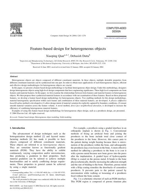
Computer-Aided Design 36 (2004) 1263–1278www.elsevier.com/locate/cad<strong>Feature</strong>-<strong>based</strong> <strong>design</strong> <strong>for</strong> <strong>heterogeneous</strong> <strong>objects</strong>Xiaoping Qian a, * ,1 , Debasish Dutta ba Inspection and Manufacturing Technologies, GE Global Research, KWD 250, One Research Circle, Niskayuna, NY 12309, USAb Department of <strong>Mechanical</strong> Engineering, University of Michigan, Ann Arbor, MI 48109-2125, USAReceived 16 June 2003; received in revised <strong>for</strong>m 22 January 2004; accepted 26 January 2004AbstractHeterogeneous <strong>objects</strong> are <strong>objects</strong> composed of different constituent materials. In these <strong>objects</strong>, multiple desirable properties fromdifferent constituent materials can be synthesized into one part. In order to obtain mass applications of such <strong>heterogeneous</strong> <strong>objects</strong>, efficientand effective <strong>design</strong> methodologies <strong>for</strong> <strong>heterogeneous</strong> <strong>objects</strong> are crucial.In this paper, we present a feature <strong>based</strong> <strong>design</strong> methodology to facilitate <strong>heterogeneous</strong> object <strong>design</strong>. Under this methodology, <strong>design</strong>ers<strong>design</strong> <strong>heterogeneous</strong> <strong>objects</strong> using high-level <strong>design</strong> components that have engineering significance. These high level components are <strong>for</strong>mfeatures and material features. In this paper, we first examine the relationships between <strong>for</strong>m features and material features in <strong>heterogeneous</strong><strong>objects</strong>. We then propose three synthesized material features in accordance with our examination of these features. Based on these proposedfeatures, we develop a feature <strong>based</strong> <strong>design</strong> methodology <strong>for</strong> <strong>heterogeneous</strong> <strong>objects</strong>. Two enabling methods <strong>for</strong> this <strong>design</strong> methodology,material heterogeneity specification within each feature and combination of these material features, are developed. A physics (diffusion)<strong>based</strong> B-spline method is developed to (1) allow <strong>design</strong> intent of material variation be explicitly captured by boundary conditions, (2) ensuresmooth material variation across the feature volume. A novel method, direct face neighborhood alteration, is developed to increase theefficiency of combining <strong>heterogeneous</strong> material features.Examples of using this feature <strong>based</strong> <strong>design</strong> methodology <strong>for</strong> <strong>heterogeneous</strong> object <strong>design</strong>, such as a prosthesis <strong>design</strong>, are presented.q 2004 Elsevier Ltd. All rights reserved.Keywords: <strong>Feature</strong> <strong>based</strong> <strong>design</strong>; Heterogeneous object modeling; Solid modeling1. IntroductionThe advancement of <strong>design</strong> techniques such as thehomogenization <strong>design</strong> method [2] and layered manufacturingmethods [6] has made it possible to have<strong>objects</strong> composed of different constituent materials.These <strong>objects</strong> are referred to as <strong>heterogeneous</strong> <strong>objects</strong>.They are sometime known as functionally gradientmaterials (FGM). They have the ability to exhibitcontinuously varying composition and/or microstructure,thus producing a gradation in their properties. Suchmaterial gradation can be tailored to achieve multiplefunctionalities and to satisfy conflicting <strong>design</strong> requirements.These properties in general cannot be achievedby using a single material.* Corresponding author. Tel.: þ1-518-387-4610; fax: þ1-518-387-5752.E-mail addresses: qian@research.ge.com (X. Qian), dutta@engin.umich.edu (D. Dutta).1 The work presented in this paper was conducted while the first authorwas at the University of Michigan.For example, a prosthesis using a graded interface in anorthopedic implant is shown in Fig. 1. Conventionalmethods of fixing an artificial bone and joining theprosthesis to the bone include total close contact ofthe prosthesis to the bone. However, this causes pain tothe patient during weight bearing because there is micromotionof the prosthesis within the bone, and subsequentlythe prosthesis may even loosen in the bone. A more effectivemethod <strong>for</strong> adhering a prosthesis to the bone is to coat itwith a porous metal because new bone grows into the poresafter the implantation. A graded layer of hydroxyapatite(HAp) is coated on the porous metal. It bonds to the bonephysicochemically, thereby increasing the adhesion strengthand the rate of binding to the bone. There<strong>for</strong>e, porous metalwith a HAp coating remedies the drawbacks of cementlessprosthesis. It prevents pain to the patient caused bymicromotion while walking or loosening of a prosthesisfixed without the bone cement.Fig. 1 is a schematic structure of such an FGM interface.This FGM region is composed of porous titanium plus0010-4485/$ - see front matter q 2004 Elsevier Ltd. All rights reserved.doi:10.1016/j.cad.2004.01.012
1264X. Qian, D. Dutta / Computer-Aided Design 36 (2004) 1263–1278Fig. 1. Schematic structure of an FGM interface within a prosthesis.hydroxyapatite (HAp). Ti has good mechanical toughnessand HAp has good biocompatibility. Simple combination ofTi and HAp would cause bio-incompatibility and weakenedstrength due to their material property differences. Suchmaterial property differences are resolved in <strong>heterogeneous</strong><strong>objects</strong> by using a mixture of Ti and HAp with varyingproportions. The sharp interface between the Ti and HAp iseliminated due to a graded zone of Ti/HAp. The bendingstrength of the resulting material is similar to a human bone.As evidenced in this example, many applications <strong>based</strong>on the concept of functionally gradient materials can bedeveloped to exploit multiple desirable material propertiesfrom different materials. In order to obtain mass applicationsof such <strong>heterogeneous</strong> <strong>objects</strong>, efficient and effective<strong>design</strong> methodologies <strong>for</strong> <strong>heterogeneous</strong> <strong>objects</strong> are crucial.Existing <strong>design</strong> methodologies are highly sophisticated, butthey are inefficient and even infeasible <strong>for</strong> handling<strong>heterogeneous</strong> <strong>objects</strong>. These methodologies are primarilydeveloped <strong>for</strong> the production of homogeneous <strong>objects</strong> ofwhich there is only one homogeneous material. Theintroduction of material variation throughout the <strong>objects</strong>adds a new dimension to the problem.The state-of-the-art research on <strong>heterogeneous</strong> objectmodeling has been primarily focusing on representationschemes <strong>for</strong> <strong>heterogeneous</strong> <strong>objects</strong>. Currently, there is onlylimited means available to obtain <strong>heterogeneous</strong> objectmodel. They are ineffective <strong>for</strong> <strong>heterogeneous</strong> object <strong>design</strong>in that these <strong>heterogeneous</strong> object models do not explicitlycapture <strong>design</strong> intent and they do not support iterative<strong>design</strong> processes.To address these issues, in this research we propose theuse of features to facilitate the <strong>design</strong> of heteorgeneous<strong>objects</strong>. In the example of the prosthesis <strong>design</strong>, the choicesof materials (Ti and HAp) and the graded interface are <strong>based</strong>on a <strong>design</strong>er’s experience and these choices have specificphysical reasons. Ti has good mechanical strength. HAp is astrorage <strong>for</strong>m of Calcium and Phosporus in the bone and ithas good bio-compatibility. We provide a <strong>design</strong> tool thatallows <strong>design</strong>ers to <strong>design</strong> such <strong>heterogeneous</strong> <strong>objects</strong> witha high level <strong>design</strong> component—features. Under thisframework, a <strong>design</strong>er can incorporate the <strong>design</strong> intuitioninto the <strong>design</strong> process. Instead of specifying materialcomposition <strong>for</strong> each spatial location within the object, theusers can choose a feature (a graded interface in thisexample) and the desired material properties at the desiredlocations when <strong>design</strong>ing the object.The remainder of this paper is organized as follows. InSection 2, we present a review of the existing researchrelating to the <strong>design</strong> of <strong>heterogeneous</strong> <strong>objects</strong>. In Section 3,a general methodology—feature <strong>based</strong> <strong>design</strong> (FBD) <strong>for</strong><strong>heterogeneous</strong> <strong>objects</strong>—is presented. Sections 4 and 5present two enabling component techniques <strong>for</strong> a feature<strong>based</strong> <strong>design</strong> method, material heterogeneity modelingwithin each material feature and constructive featureoperations <strong>for</strong> combining material features. Section 6presents the implementation and examples of the feature<strong>based</strong> <strong>design</strong> methodology, including the feature <strong>based</strong><strong>design</strong> process <strong>for</strong> the prosthesis <strong>design</strong>. Finally, Section 7summarizes this paper.2. Literature reviewMany representation schemes have been developed torepresent solids. Manifold solids and R-sets were firstproposed to represent solid model [8,25]. Radial-edge datastructure is another data structure <strong>for</strong> modeling nonmanifoldsolid [32]. For conventional feature modeling,the usage of non-manifold structure was first proposed byPratt [19]. Selected Geometric Complex (SGC) is a nonregularizednon-homogeneous point set represented throughenumeration as union of mutually disjoint connected opencells [26]. Constructive Non-Regularized Geometry(CNRG) was also proposed to support dimensionallynon-homogeneous, non-closed point sets with internalstructures [27]. Middleditch et al. presented mathematics
X. Qian, D. Dutta / Computer-Aided Design 36 (2004) 1263–1278 1265and <strong>for</strong>mal specification <strong>for</strong> the mixed dimensional cellulargeometric modeling [16].Current research on <strong>heterogeneous</strong> <strong>objects</strong> has led tomany representation schemes <strong>for</strong> <strong>heterogeneous</strong> objectmodeling. Kumar and Dutta proposed R-m sets be used<strong>for</strong> representing <strong>heterogeneous</strong> <strong>objects</strong> [12]. Jackson et al.proposed another modeling approach <strong>based</strong> on subdividingthe solid model into sub-regions and associating theanalytical composition blending function with each region[10,11]. Park et al. presented a volumetric texturingapproach <strong>for</strong> modeling <strong>heterogeneous</strong> <strong>objects</strong> [17]. Biswaset al. proposed a distance field <strong>based</strong> approach <strong>for</strong><strong>heterogeneous</strong> object modeling, in which the space isparametrized by distance to the geometry boundaries [4].Huang and Fadel employed a Bezier basis function <strong>for</strong>optimizing material heterogeneity in flywheel [9]. Dutta[29] and Tan [30] presented constructive approaches <strong>for</strong><strong>heterogeneous</strong> object modeling. Kumar and Dutta presenteda trivial fiber-bundle <strong>based</strong> model to represent severalattributes of an object along with the geometry [13]. Paskoet al. used a functional representation (Frep) to constructivelymodel object geometry and properties of arbitrarynature [18].Even though existing representation schemes <strong>for</strong> <strong>heterogeneous</strong><strong>objects</strong> provide means to represent <strong>heterogeneous</strong><strong>objects</strong>, they do not necessarily support the <strong>heterogeneous</strong>object <strong>design</strong> process. The current methods <strong>for</strong> specifyingmaterial composition face a trade-off between the modelcoverage and operation convenience [23]. These methodsonly provide a low level description of geometry andmaterial composition within the <strong>objects</strong>. The characteristicsof material variation are not explicitly captured. Theresulting material properties are often not available <strong>for</strong><strong>design</strong>ers. These methods do not provide effective tools <strong>for</strong><strong>design</strong>ers to create and edit the <strong>heterogeneous</strong> object model.In the domain of homogeneous <strong>objects</strong>, featuremethodologies have been extensively researched to facilitatetheir <strong>design</strong> and fabrication. <strong>Feature</strong>s were initiallyproposed to automate the link between <strong>design</strong> and NC pathgeneration [7]. Since then, feature techniques have beenwidely and successfully used in CAD/CAM systems.<strong>Feature</strong>-<strong>based</strong> <strong>design</strong> expedites the <strong>design</strong> process andfeature recognition facilitates the fabrication processplanning. A feature-<strong>based</strong> product model also simplifiesthe assembly, inspection planning, and other downstreamapplications [28].In order to facilitate the <strong>design</strong> and fabrication of<strong>heterogeneous</strong> <strong>objects</strong>, Qian and Dutta proposed the usageof feature methodologies <strong>for</strong> the <strong>design</strong> and layeredmanufacturing of <strong>heterogeneous</strong> <strong>objects</strong> [20,21]. Thispaper will present some of the results. Liu et al. alsopresented their feature <strong>based</strong> <strong>design</strong> approach to achievelocal control of material properties, in which they usedthe Laplace equation to create material compositionblending [14].3. <strong>Feature</strong> <strong>based</strong> <strong>design</strong> <strong>for</strong> <strong>heterogeneous</strong> <strong>objects</strong>In this section, we examine the relationships between<strong>for</strong>m features and material features in <strong>heterogeneous</strong><strong>objects</strong>. We synthesize <strong>for</strong>m features and material featuresand we propose a constructive feature <strong>based</strong> <strong>design</strong> method<strong>for</strong> <strong>heterogeneous</strong> <strong>objects</strong>.3.1. <strong>Feature</strong>s<strong>Feature</strong> techniques, traditionally, have only been focusingon the geometry, i.e. <strong>for</strong>m features. Because of thenature of material variation in <strong>heterogeneous</strong> <strong>objects</strong>, weshall examine features not only in terms of the geometry butalso in terms of the material composition in a part.In order to mathematically represent the features, we firstdefine some notations. A part, PðG; MÞ; is defined as aproduct space, where G is the geometry and M is thematerial space.3.1.1. Form featureForm feature is a specific geometric shape, which carriesengineering significance, such as a hole and a slot. A <strong>for</strong>mfeature can be either a volume feature or a surface feature. Inthis paper, we focus on volume features.As with homogeneous <strong>objects</strong>, a <strong>for</strong>m feature in<strong>heterogeneous</strong> <strong>objects</strong> is a specific shape within a partregardless of the material composition variation. In order todistinguish <strong>for</strong>m features from material features, we notetwo necessary conditions to the definitions of <strong>for</strong>m features.First, the shape of the volume must correspond to somespecific engineering meaning. For example, <strong>for</strong>m featuressuch as a hole or a groove, have specific geometric shapesand engineering significance. Second, such a shape shouldcontribute to the <strong>for</strong>mation of the boundary of the final partgeometry. That is to say, during the part creation process,the evolving part geometries should be different be<strong>for</strong>e andafter the introduction of the <strong>for</strong>m features. We note the partgeometry as G i be<strong>for</strong>e the <strong>for</strong>m feature FF iþ1 is introducedto the part. Then the second necessary condition <strong>for</strong> <strong>for</strong>mfeatures can be represented as: FF iþ1 2 G i – B: This willbe further explained in Section 3.1.3.For example, in Fig. 2, the <strong>heterogeneous</strong> object hasthree <strong>for</strong>m features: a block, a hole, and a boss. They eachrepresent a particular geometric shape. If we disregard thematerial variation in the object, these three <strong>for</strong>m featurescreate the final geometry of the object. In the two FGMregions, FGM1 is a <strong>for</strong>m feature while FGM2 is not. FGM2does not satisfy the second condition of <strong>for</strong>m feature, i.e.FGM2, as a shape, does not contribute to the boundary offinal part geometry.3.1.2. Material featureBe<strong>for</strong>e we present the definition of material features, wefirst examine material variation in <strong>heterogeneous</strong> <strong>objects</strong>.
1266X. Qian, D. Dutta / Computer-Aided Design 36 (2004) 1263–1278Fig. 2. <strong>Feature</strong>s in a <strong>heterogeneous</strong> object.Heterogeneous materials arise in materially optimizedstructures where the material composition and distributionare optimized to maximize the desired per<strong>for</strong>mancemeasures. They provide a smooth transition among differentmaterials. The material variation usually correspond tosome particular functionality and <strong>design</strong> intent. They can beexplicitly captured by a material volume, <strong>for</strong>mally amaterial feature. Such a material volume can be representedin many different ways, e.g. a swept material volume [21](See Fig. 3) or a B-spline material volume [23].Swept material volume. Swept material volume iscomposed of a cross-section and a path. The materialcould vary along the cross-section and/or along the path.Conventionally, a swept volume S (Fig. 3) is defined bysweeping a surface rðu; vÞ along path pðwÞ: If ‘ p ’ denotessweep, the swept material primitive (SM) (Fig. 3) could bewritten asdescription of such a representation and the correspondingmodeling method.A material feature is a region with some particularmaterial composition variation and this material variationfunction is different from the neighboring volume’s materialfunctions. Such material composition variation is associatedwith some engineering significance, such as erosionprotection, thermal balance, and biocompatibility.A material feature is an enriched material volume. Therelationship between a material feature and the materialvolume is similar to the relationship between a <strong>for</strong>m featureand the geometric volume. The features contain engineeringrelevance while the volumes do not. Material features canbe represented as a pair, MFðg; mÞ; where m has certaincharacteristics in the region g and is different from thematerial function elsewhere.SMðS; MÞ ¼ðrðu; vÞ p pðwÞ; mðu; v; wÞÞwhere S represents the geometric volume, M represents thematerial composition, and material variation functionmðu; v; wÞ represents the material changes along the crosssectionrðu; vÞ and path pðwÞ: The material variation functioncould be any user-defined function (e.g. constant, linear,step function, parabolic, exponential, etc.) [15]. Thefunction mðu; v; wÞ would enable full three dimensionalmaterial variation. In practice, material variation typicallywould happen only along one of the u; v; w directions,denoted as mðuÞ; mðvÞ and mðwÞ:B-spline material volumeA more general representation of material volumes canbe represented in a B-spline solid. Section 4 gives a detailedFig. 3. Swept material volume.
1268X. Qian, D. Dutta / Computer-Aided Design 36 (2004) 1263–1278Fig. 5. Relationships between <strong>for</strong>m features and material features.In STEP [31], the volume features <strong>for</strong> homogeneous<strong>objects</strong> are classified as additive and subtractive features. Inconsistency with <strong>for</strong>m feature classification in the STEP andthe observed feature properties in <strong>heterogeneous</strong> <strong>objects</strong>, wepropose the following feature operations in the context of<strong>heterogeneous</strong> object <strong>design</strong>: additive material feature,subtractive material feature and partition material feature(Fig. 6). In responding to additive and subtractive features inSTEP, we propose additive and subtractive materialfeatures. In responding to the partition properties (Observation1) of material features in <strong>heterogeneous</strong> <strong>objects</strong>, wepropose partition material features. This classification is<strong>based</strong> on the modeling operation’s impact on geometry.Be<strong>for</strong>e we present the details of the semantics definition<strong>for</strong> each feature operation, we define some terms. For anobject or a region Aðg; mÞ; mðAÞ gives the materialin<strong>for</strong>mation m; pðAÞ is the priority of the materials and itis useful when different materials are interacting with eachother.As noted be<strong>for</strong>e, ‘l’ is the aggregate/gluing operation. ‘l p ’is the regularized gluing operation. For each face, ifmaterial functions over the face’s two adjacent regions areequal, the face shall be eliminated. That is, ðg 1 ; m 1 Þl pðg 2 ; m 2 Þ¼ðg 1 < p g 2 ; m 12 Þ when material function equalityconditions are satisfied.The three generic (synthesized) feature operations can bedefined respectively as:3. Partition material featureðg 1 ; m 1 Þ=ðg 2 ; m 2 Þ¼ðg 1 2 g 2 ; m 1 Þl p ðg 1 > g 2 ; m 1^m 2 ÞFig. 7 lists the three types of features and their semantics.Clearly, the resultant part C of two features A and B; C ¼A^B; depends on the feature type (operation), and eachregion’s materials and the priority tag.To resolve the material composition ambiguity over theintersection region, we introduce the material priority tag p;to each material volume. That is,8m 1 ; if p 1 . p 2>:m 1 %m 2 ; if p 1 ¼ p 2Note, here m 1 %m 2 is a user defined function. It could bea·m 1 þð1 2 aÞ·m 2 ; a [ ð0; 1Þ; or any other <strong>for</strong>m. m 1 %m 2has been particularly useful <strong>for</strong> applications like modelingdoping and implanting, where material volume is ‘contaminated’by some exotic materials.How material composition change during the synthesizedfeature operation is referred to as materialoperation semantics.1. Additive material featureðg 1 ; m 1 Þþðg 2 ; m 2 Þ¼ðg 1 2 g 2 ; m 1 Þl p ðg 2 2 g 1 ; m 2 Þl p ðg 1 > g 2 ; m 1^m 2 Þ2. Subtractive material featureðg 1 ; m 1 Þ 2 ðg 2 ; m 2 Þ¼ðg 1 2 g 2 ; m 1 ÞFig. 6. A proposal <strong>for</strong> feature classification in <strong>heterogeneous</strong> <strong>objects</strong>.
X. Qian, D. Dutta / Computer-Aided Design 36 (2004) 1263–1278 1269processes involving different materials. The three featuresprovide a generic tool <strong>for</strong> <strong>heterogeneous</strong> object modeling.Many existing <strong>design</strong>/fabrication automation tools <strong>for</strong><strong>heterogeneous</strong> <strong>objects</strong> processing are dedicated tools andthey can be directly derived from these three synthesizedfeatures. For example, the feature operation semantics usedin <strong>design</strong> by composition <strong>for</strong> layered manufacturing [3] andMEMS fabrication process simulation [5] can all be derivedfrom the synthesized features [20].Based on these synthesized feature operations, a feature<strong>based</strong> <strong>design</strong> methodology has been developed <strong>for</strong> <strong>heterogeneous</strong>object <strong>design</strong> [20]. In our implementation, weadopted the R-m set as the working representation scheme<strong>for</strong> <strong>heterogeneous</strong> <strong>objects</strong>, even though other representationschemes can also be used to represent the semantic featuresdefined above. That is, in our implementation, an R-m setðg; mÞ is used as the building block <strong>for</strong> the constructive<strong>design</strong>. A compound feature (building block), consisting ofmore than one R-m set, can also be defined, i.e. a finitecollection of R-m sets, ðg 1 ; m 1 Þ; ðg 2 ; m 2 Þ; …; ðg n ; m n Þ; eachconsisting of a material volume. To support a constructive<strong>design</strong> of <strong>heterogeneous</strong> <strong>objects</strong>, we extended the radialedgegraph to represent the geometry of <strong>heterogeneous</strong><strong>objects</strong> [24]. In this extended data structure, each region hasits material composition representation and each face usehas neighborhood in<strong>for</strong>mation, which contains a pointerpointing to material representation. Such a methodologyneeds two enabling component techniques: how to definematerial composition within each material volume and howto combine material volumes. These two enabling techniquesare presented in Sections 4 and 5.Fig. 7. Generic feature operations <strong>for</strong> <strong>heterogeneous</strong> <strong>objects</strong>.The partition feature functions the same as additivefeatures over the intersection region ðg 1 > g 2 Þ; but it is notapplicable to the region outside of g 1 : This partition featureis used extensively <strong>for</strong> <strong>heterogeneous</strong> object modeling whenmaterial functions are imposed on a given geometrydomain.These synthesized features support both <strong>for</strong>m feature andmaterial feature operations. It associates each materialvolume with one geometric/material operator. They precluderedundant definitions of the geometry in both <strong>for</strong>mfeatures and material features. The four types of relationshipsbetween the geometric volumes of <strong>for</strong>m features andmaterial features can be fully manifested by the synthesizedfeatures in a constructive approach. In this approach, thebuilding blocks are the synthesized features. The <strong>design</strong>erhas two choices: either use the default materials to model<strong>for</strong>m features and then partition the part volume withspecific material composition functions, or glue a set ofmaterial feature volumes.These synthesized feature operations can be used to<strong>design</strong> <strong>heterogeneous</strong> <strong>objects</strong> or simulate manufacturing4. Material heterogeneity modeling <strong>based</strong>on <strong>design</strong> intentIn order to use synthetic material features as a buildingblock <strong>for</strong> feature <strong>based</strong> <strong>design</strong>, we need a method to definematerial heterogeneity within each feature volume that canrepresent <strong>design</strong> intents. During the iterative <strong>design</strong> editingprocess, these <strong>design</strong> intents need to be preserved. In thissection, we present a method in which <strong>design</strong>er specifymaterial variation within a feature volume through<strong>design</strong>ers’ intuition and experience.We use a B-spline tensor solid to represent a synthesizedmaterial feature volume. We use a virtual diffusion processto create material heterogeneity profile. The <strong>design</strong> intentsare represented as a set of constraints. The detailedmathematical <strong>for</strong>mulation is available in Refs. [20,22,23].Solving diffusion equations under these constraints willautomatically ensure the material variation is smooth withineach material volume. In order to make this paper selfcontained,we briefly present the material heterogeneitymodeling method here, with emphasis on how <strong>design</strong> intentscan be represented and preserved within a feature during theediting process.
1270X. Qian, D. Dutta / Computer-Aided Design 36 (2004) 1263–12784.1. B-spline tensor solid representation<strong>for</strong> material featuresIn order to represent free<strong>for</strong>m geometry and arbitrarymaterial variation within a synthesized material feature, weuse a B-spline tensor solid as a representation. For eachpoint ðu; v; wÞ in the parametric domain of a tensor productB_spline volume V; there is a corresponding point Vðu; v; wÞat Cartesian coordinates ðx; y; zÞ with material compositionM; noted as ðx; y; z; MÞ: We define such a B-spline volume as:Vðu; v; wÞ ¼ XnX mX li¼0 j¼0 k¼0N i;p ðuÞN j;q ðvÞN k;r ðwÞP i;j;kwhere P i;j;k ¼ðx i;j;k ; y i;j;k ; z i;j;k ; M i;j;k Þ are control points <strong>for</strong> the<strong>heterogeneous</strong> solid volume. N i;p ; N j;q and N k;r are the pthdegree,qth-degree and rth-degree B-spline functions definedin the direction of u; v; w; respectively. We can also have theB-spline representation <strong>for</strong> material properties:Eðu; v; wÞ ¼ XnX mX li¼0 j¼0 k¼0N i;p ðuÞN j;q ðvÞN k;r ðwÞE i;j;kwhere E i;j;k is material property at each control point. It canbe obtained according to the volume fractions at each point.The relationship between material properties and thecomposition has been extensively studied [15]. For example,Eqs. (3) and (4) give the approximate relationships ofthermal conductivities and mechanical strengths versusmaterial composition. M a ; M b are volume fractions of twocomposite materials at each point. l a ; l b are thermalconductivities and S a ; S b are strengths <strong>for</strong> two materials aand b:ll ¼ l a M a þ l b M b þ M a M a 2 l bb3=ðl b =l a 2 1ÞþM aS ¼ S a·M a þ S b·M b4.2. Diffusion <strong>based</strong> heterogeneity creationIn this section, we describe how diffusion processgenerates different material composition profiles. Diffusionis a common physical process <strong>for</strong> the <strong>for</strong>mation of materialheterogeneity such as in integrated circuit fabrication, inbiological mass transport, and in the drug delivery from apolymer.The mathematical modeling of controlled materialcomposition in these processes is <strong>based</strong> on the Fick’s lawsof diffusion. Applying Fick’s laws and using the divergencetheorem, we have the following equation <strong>for</strong> a diffusionprocess, in which M represents the material concentration(volume fraction <strong>for</strong> our purpose), Q is material generationð1Þð2Þð3Þð4Þsource and D ij is the diffusivity.dM¼ Q þ › D ›M!dt ›x ij·i ›x jBy the B-spline finite element approximation, we haveKM ¼ kB 2 kSwhere ð¼ kK eN£NkB eN£IV eð¼ N m Q dVV e›N i›x · ›N j›x þ ›N i›y · ›N j›y þ ›N i›z · ›N jdV›z; kS eN£Ið¼ N m q n dGG eWith function Q and q interpolated in terms of its nodalvalues, we have kB eN£I ¼½ Ð V eNi m Nj m dVŠQ j ; and kS eN£I ¼½ Ð G eNi m Njm dGŠq j : K e is the element stiffness matrix, and kB eis the element body <strong>for</strong>ce and kS e is the element surface <strong>for</strong>ce.4.3. Design intent (constraints) <strong>based</strong> heterogeneitymanipulationThe above <strong>for</strong>mulation has provided a methodology tocalculate the material composition <strong>for</strong> a diffusion process. Itcan be generalized <strong>for</strong> manipulating material composition ofB-spline <strong>heterogeneous</strong> solid <strong>objects</strong> by imposing constraints,i.e. boundary conditions. These constraints arerepresentation of <strong>design</strong> intent.The constraints that are imposed on the B-solid includethe heterogeneity in<strong>for</strong>mation on the boundary, or theheterogeneity at specific location ðu; v; wÞ; or any other typeof constraints that can be trans<strong>for</strong>med into a set of equations.Here, we consider a set of linear constraints:A·M ¼ ETo accommodate the constraints in Eq. (9), solutionmethods generally trans<strong>for</strong>m this to an unconstrainedsystem: minkð1=2Þð M T K M 2 M T Bk; in which solutions M;when trans<strong>for</strong>med back to M; are guaranteed to satisfy theconstraints. The unconstrained system is at a minimumwhen its derivatives are 0, thus we are led to solve thesystem K M ¼ B: Specifically, we introduce a Lagrangemultiplier <strong>for</strong> each constraint row A i ; and we then minimizethe unconstrained min p kð1=2ÞðM T KM2M T BþðAM2FÞGÞk:Differentiating with respect to M leads to the augmentedsystem:"K A T # " # "M· ¼B #ð10ÞA 0 G FSolving the above linear equations leads to the solution to theconstrained system. Note, in this paper, <strong>for</strong> the sake of savingcomputational time, only linear constraints are considered.ð5Þð6Þð7Þð8Þð9Þ
X. Qian, D. Dutta / Computer-Aided Design 36 (2004) 1263–1278 1271Fig. 8. Material variation created by a diffusion process.However, it is not difficult to generalize the method toaccommodate non-linear constraints by en<strong>for</strong>cing Lagrangemultiplier techniques.Two diffusion processes are shown in Fig. 8, one withconcentration source from top face, one with concentrationsource from top/right edge. We obtained the <strong>heterogeneous</strong><strong>objects</strong> by imposing the concentration source constraints onthe face and the edge respectively.We relate material variation <strong>design</strong> in a material featureto a mass transport problem in a virtual diffusion process.Designers can utilize the intuition <strong>based</strong> on diffusion lawand impose boundary conditions accordingly (in terms ofmaterial generation source, diffusivity, and material compositionat particular spatial locations) as opposed tomanipulate the material variation value at each controlpoint in the native B-spline representation. We use theseconstraints to adjust material variation and preserve <strong>design</strong>intent. That is, the <strong>design</strong>er’s role has been elevated fromquantitatively manipulating control point to qualitativelyimposing constraints. Our <strong>heterogeneous</strong> object modelingengine will then automatically compute the materialvariation value at each control point. Thus, many desirableB-spline properties such as local control are still preserved.If needed to be, users can still fine-tune the materialvariation through the B-spline representation. Sincematerial variation and geometry are represented in a sameB-spline solid, the <strong>design</strong> intent of material variation(constraints) is automatically maintained when the geometryis changed. Examples in Section 6 will furtherdemonstrate this.5. Constructive feature operations through direct faceneighborhood alterationOnce synthesized material features are constructed,they need to be combined together to build the finalpart through three feature operations: addition,subtraction and partition. Given <strong>heterogeneous</strong> <strong>objects</strong>A ¼ {A 1 lA 2 l···lA m } and B ¼ {B 1 lB 2 l···lB n } and thefeature operator ^; the resultant solid needs to be<strong>for</strong>med. It essentially includes two tasks:† determine the boundary of A and B that appears in theresultant solid C (Geometric Boundary Evaluation), and† organize the resultant faces into regions and associatematerial function m i to each region g i (Material RegionForming).These feature operations can be trans<strong>for</strong>med intotraditional Boolean operations with appropriate processingof material variation attributes. However, in this research,both the geometric boundary evaluation and materialregion <strong>for</strong>ming are conducted <strong>based</strong> on a novel method,direct face neighborhood alteration [20,24], to increase themodeling efficiency. We only briefly describe the concepthere.Neighborhood is a well-known concept from topology[1]. In <strong>heterogeneous</strong> <strong>objects</strong>, each face has two neighboringregions. We perceive a 3D face’s neighborhood as a twosidedface neighborhood NF and represent it as acombination of two one-sided face neighborhood NF fromeach adjacent region.Given the <strong>objects</strong> A and B; the faces from A and B;noted as F A and F B ; can be classified against each other.There are five types of set membership classification(SMC) values: F A in B; F A out B; F A on B/F B on A; F Bin A; and F B out A: There<strong>for</strong>e, corresponding to the fiveSMC values, there are five NF operations <strong>for</strong> theoperation A^B : (1) NF A^B j <strong>for</strong> F A inside region B j ;(2) A^NF B <strong>for</strong> F B inside region A i ; (3) NF A^NF B <strong>for</strong> F Aand F B that are co-faces, (4) NF A^B C <strong>for</strong> F A outside theobject B, i.e. F A interacts with region B C , (5) A C^NF B<strong>for</strong> F B outside the object A, i.e. F B interacts with regionA C . Fig. 9 shows the five neighborhood operations. Sincedifferent regions have different material operation semantics,the NF operations are fulfilled by combining twoseparate one-sided NF operations, each of which operatesaccording to the residing region’s semantics.F A ’s neighborhood operation with region B j can berepresented as:NF A^B j ¼ðnF AFront^B j ÞlðnF ABack^B j Þ
1272X. Qian, D. Dutta / Computer-Aided Design 36 (2004) 1263–1278Fig. 9. Face membership classification and neighborhood operation.Here nF AFront and nF ABack refer to the face F A ’s front regionand back region’s neighborhood. For the generality, onesidedface neighborhood in region A i is referred to as nF Ai :The face neighborhood <strong>for</strong> the object A’s complement set A cis noted as nF A c:An example of F A interacting with region B is shownin Fig. 10 (bold line). From the four cases in theunion operation, we have the following neighborhoodalteration rules:8nF Ai>< nF AinF Ai< B j ¼ðdirA i ; mBÞ>:ðdirA i ; mA%mBÞmA ¼ mBpA . pBpA , pBpA ¼ pBð11ÞFig. 10. Neighborhood operations <strong>for</strong> FA in B.
X. Qian, D. Dutta / Computer-Aided Design 36 (2004) 1263–1278 1273The other types of face neighborhood alteration can bederived similarly.Both modeling tasks <strong>for</strong> constructive feature operations,boundary evaluation and material region <strong>for</strong>ming,can then be derived from the altered neighborhoodin<strong>for</strong>mation.6. Implementation and examplesA prototype system <strong>for</strong> feature <strong>based</strong> <strong>design</strong> methodologyhas been implemented using ACIS on a SUN Sparcworkstation. This section presents the implementationresult. Note some examples have appeared in our priorpublications [23,24] and we describe in this paper how thefeature <strong>based</strong> <strong>design</strong> method is used to <strong>design</strong> geometry andmaterial variation within these parts.6.1. Example 1: manipulating geometry while preserving<strong>design</strong> intent in a material featureFor each material primitive, the input of the system is aB-spline solid, consisting of a set of control points. The userinteracts with system in two ways. First, the user can changesystem parameters, such as Q; the material source(material/unit volume) and D; the material diffusioncoefficient. Second, the user can impose constraints. Thetwo types of interaction processes continue until the user issatisfied with the result.Fig. 11 shows an example of changing both geometry andmaterial composition. The top of Fig. 11 is an initial B-spline solid, imposed with constraints on two boundarysurfaces. Fig. 11a is the result. We can change the geometryof the solid and get the new solid in Fig. 11b and thenimpose composition constraints. This leads to a new solid inFig. 11d. We can also impose the material compositionconstraints first (Fig. 11c) and then manipulate the geometry(Fig. 11d). This alteration of geometry and materialcomposition manipulation sequence leading to the sameresult demonstrates the <strong>design</strong> intent can be preservedduring the iterative <strong>design</strong> editing process.6.2. Example 2: material properties directly conceivableto <strong>design</strong>ersA <strong>heterogeneous</strong> feature with graded materials, SiC andAl6061 alloy, is shown in Fig. 12. The thermal conductivitiesof the two materials are 180 and 25 W/mK. Thestrengths are þ145/2145 MPa and þ0/28300 MPa. UsingEqs. (3) and (4), we can have the thermal conductivity andtensile/compression stress <strong>for</strong> each control point. Theseproperties are respectively shown in Fig. 12. Fig. 12 alsoshows the values at the tip. Note, the notation a=ðb; cÞ in thefigure means the value at the tip point is a while the minimalvalue of the whole volume is b; and the maximum value is c:The combination of SiC and Al alloy enables heat resistanceand anti-oxidation properties on the high temperature side,mechanical toughness and strength on the low temperatureFig. 11. Design intent is preserved during the iterative <strong>design</strong> process.
1274X. Qian, D. Dutta / Computer-Aided Design 36 (2004) 1263–1278Fig. 12. Material properties directly conceivable to <strong>design</strong>ers.side, and effective thermal stress relaxation throughout thematerial.Suppose the <strong>design</strong>er is not satisfied with the strength atthe tip of turbine blade, the <strong>design</strong>er can choose to strengthenthe tip by imposing constraints at the tip. The revised modelis shown in Fig. 13, where the thermal conductivity has beenchanged from 25 to 140.94, tensile strength from 0 to 116.92and compression strength from 8300 to 1724.37.Fig. 13. Improving the tip strength at the tip.
X. Qian, D. Dutta / Computer-Aided Design 36 (2004) 1263–1278 1275Fig. 14. Constructive feature operations.Using this method, the <strong>design</strong>ers directly interact withthe system with familiar concepts (the material properties)rather than material composition. We believe thisdirect quantitative feedback of material properties isparticularly useful <strong>for</strong> a <strong>design</strong>er during the <strong>design</strong>evolution process.6.3. Example 3: constructive feature operationsFig. 14 shows a sample part, consisting of two featurevolumes, A and B: By direct face neighborhood alteration,the system gives different results, depending on the priorityof each material feature primitive. The right half of thefigure is the shaded cross-section of the parts. The featureoperations are additive. Partition operations can also be usedto get the same result.6.4. Example 4: using feature <strong>based</strong> <strong>design</strong> methodto simulate a MEMS fabrication processFig. 15 shows a MEMS fabrication process modeledthrough the system. Since MEMS fabrication involvesgeometric changes of different materials, a feature <strong>based</strong><strong>design</strong> method can simulate the fabrication process. Twotypes of operations, additive and subtractive, are used. Inthis example, each fabrication step is represented in amaterial feature. The color changes illustrate the faceneighborhood changes during the modeling process. In thelast step (Fig. 15e) Electrode overrides Acetone. So allFig. 15. Using FBD to simulate a MEMS fabrication process.
1276X. Qian, D. Dutta / Computer-Aided Design 36 (2004) 1263–1278Fig. 16. Flowchart of a feature <strong>based</strong> <strong>design</strong> process <strong>for</strong> a new prosthesis.the neighborhood of the faces from Acetone are changed toElectrode if they are ‘inside’ Electrode.6.5. Example 5: using FBD to <strong>design</strong> a prosthesis structureThe following example of prosthesis <strong>design</strong> demonstratesa typical feature <strong>based</strong> <strong>design</strong> process <strong>for</strong> <strong>heterogeneous</strong>parts. Fig. 16 shows a flowchart <strong>for</strong> the prosthesis<strong>design</strong> process. Starting from the <strong>design</strong> functions, usersselect materials and <strong>for</strong>m the <strong>heterogeneous</strong> materialfeatures, each of which is a B-spline volume. The featurecombination algorithm combines these features into a<strong>heterogeneous</strong> object. After the mechanical and biologicalproperties are obtained from the database <strong>for</strong> eachindividual material, these properties at each point in thisprosthesis can then be evaluated. If users are not satisfiedwith the properties, they can select new material <strong>for</strong>each volume or change volume fractions. These stepsof changing material composition of each feature inthe constructive process <strong>for</strong>m a feature <strong>based</strong> <strong>design</strong>process. After the property evaluation, property in vitrotests and animal tests are conducted be<strong>for</strong>e the <strong>design</strong>edprosthesis is used <strong>for</strong> medical purposes.In the example of Fig. 17 is a prosthesis <strong>design</strong>edfollowing the flow chart in Fig. 16. The materials areTitanium and graded HAp. Each of these <strong>design</strong> intents isrepresented as a separate B-spline volume (<strong>heterogeneous</strong>feature), such as in Region 2 and Region 7 in Fig. 17. Inthese two regions, pore and HAp are modeled as onematerial, while the Titanium is the other material. Becauseof the <strong>design</strong> intent of having a graded interface, we set theboundary conditions on inner surface and outer surface ofthe two regions. Regions 1 and 8 represent the bones.Regions 4 and 5 connect the two ends. Once the volumefraction <strong>for</strong> pore and HAp is known, another fraction is usedto separate the pore and HAp. This fraction is constantthroughout the region. The Fig. 17a and b show the gradedporous structure and graded HAp, respectively, withFig. 17. Graded interface modeling within a prosthesis.
X. Qian, D. Dutta / Computer-Aided Design 36 (2004) 1263–1278 1277Fig. 18. Variation of Young’s modulus and biofunctionality due to Q change.the M pore =M HAp ¼ 0:5: Fig. 17c shows the constructionhistory. The partition in the construction history is similar tounion operation but with the intersection region’s materialredefined. Modification to the material composition can leadto different Young’s modulus and biofunctionality (BF)distribution throughout the region. In Fig. 18, we show theproperties variation due to the change of Q (materialgeneration source). These values are measured at differentdistance points from the inner surfaces of the gradedregions.This example demonstrates that the feature <strong>based</strong> <strong>design</strong>method not only provides an intuitive way to control thematerial compositions but also provides means to directlycontrol the material properties. This draws a distinctionfrom existing <strong>design</strong> methods <strong>for</strong> the prosthesis <strong>design</strong>,where material composition <strong>design</strong> and material propertyevaluation are conducted separately and sequentially.7. ConclusionsThis paper has addressed an important issue in<strong>heterogeneous</strong> object realization—feature <strong>based</strong> <strong>design</strong>methodology <strong>for</strong> <strong>heterogeneous</strong>.In the context of <strong>heterogeneous</strong> object <strong>design</strong>, wepropose the use of features to facilitate the high level(explicit) conceptualizing of geometric shape and materialgradation. Based on our examination of the relationshipsbetween <strong>for</strong>m features and material features in <strong>heterogeneous</strong><strong>objects</strong>, a feature <strong>based</strong> <strong>design</strong> methodology isdeveloped <strong>for</strong> <strong>heterogeneous</strong> object <strong>design</strong>. It is aconstructive <strong>design</strong> process <strong>based</strong> on a set of user predefined<strong>heterogeneous</strong> features. The constructive featureoperations include additive, subtractive and partition. Tomodel material heterogeneity effectively and efficientlywithin each feature, a physics <strong>based</strong> B-spline <strong>heterogeneous</strong>object modeling method is researched and developed. In thismethod, B-spline representation is utilized to increasemodel coverage, and a physics process (diffusion process)is used to generate material composition profile to increaseoperation convenience. To speed up the efficiency ofconstructive feature operations, a direct face neighborhoodalteration method is developed.Our contributions in this paper include (1) the examinationof the inherent relationships between <strong>for</strong>m featuresand materials features, (2) the proposal of three synthesizedfeatures operations, and (3) the development of two enablingtechniques <strong>for</strong> feature <strong>based</strong> <strong>design</strong>: physics-<strong>based</strong> B-splineobject heterogeneity modeling and direct face neighborhoodalteration <strong>for</strong> constructive feature operations.AcknowledgementsWe gratefully acknowledge the financial support fromNSF (grant MIP-9714751).References[1] Armstrong MA. Basic topology. New York: Springer; 1983.[2] Bendose MP, Kikuchi N. Generating optimal topologies in structural<strong>design</strong> using a homogenization method. Comput Meth Appl MechEngng 1988;71:197–224.[3] Binnard M, Cutkosky MR. A <strong>design</strong> by composition approach <strong>for</strong>layered manufacturing, ASME transactions. J Mech Des 2000;122(1):91–101.[4] Biswas A, Shapiro V, Tsukanov I. Heterogeneous material modelingwith distance fields. Technical Report, Spatial Automation Lab,University of Wisconsin-Madison; 2002.[5] Dixit H, Taylor D, Kannapan S. 3D geometric simulation of memsfabrication processes: a semantic approach. Proceedings of FourthSymposium on Solid Modeling and Applications, Atlanta, Georgia;1997.[6] Dutta D, Prinz FB, Rosen D, Weiss L. Layered manfuacturing: currentstatus and future trend. ASME J Comput In<strong>for</strong>mation Sci Engng 2001;1:60–71.[7] Grayer A. A computer link between <strong>design</strong> and manufacture. PhDDissertation, University of Cambridge, UK; September 1976.[8] Hoffmann CM. Geometric and solid modeling: an introduction. ;1989.[9] Huang J, Fadel GM. Heterogeneous flywheel modeling andoptimization. J Mater Des 2000;21:111–25.[10] Jackson T. Analysis of functionally graded material object representationmethods. PhD Dissertation, MIT; February 2000.
1278X. Qian, D. Dutta / Computer-Aided Design 36 (2004) 1263–1278[11] Jackson T, Liu H, Patrikalakis NM, Sachs EM, Cima MJ. Modelingand <strong>design</strong>ing functionally graded material components <strong>for</strong> fabricationwith local composition control, materials and <strong>design</strong>, specialissue. The Netherland: Elsevier Science; 1999.[12] Kumar V, Burns D, Dutta D, Hoffmann C. A framework <strong>for</strong> objectmodeling. Comput-Aid Des 1999;31(9):541–56.[13] Kumar V, Dutta D. An approach to modeling and representation of<strong>heterogeneous</strong> <strong>objects</strong>. ASME J Mech Des 1998;120(4).[14] Liu H, Maekawa T, Patrikalakis NM, Sachs EM, Cho W. Methods <strong>for</strong>feature-<strong>based</strong> <strong>design</strong> of <strong>heterogeneous</strong> solids, MIT Design LaboratoryMemorandum 03-1.[15] Markworth AJ, Tamesh KS, Rarks Jr WP. Modeling studies applied tofunctionally graded materials. J Mater Sci 1995;30:2183–93.[16] Middleditch AE, Reade CMP, Gomes AJ. Set-combinations of themixed dimensional cellular <strong>objects</strong> of the Djinn API. Comput-Aid Des1999;31:683–94.[17] Park S.-M. Craw<strong>for</strong>d RH, Beaman JJ. Functionally gradient materialrepresentation by volumetric multi-texturing <strong>for</strong> solid free<strong>for</strong>mfabrication. 11th Annual Solid Free<strong>for</strong>m Fabrication Symposium,Austin, TX; August 7–9, 2000.[18] Pasko, Adzhiev V, Schmitt B, Schlick C. Constructive hypervolumemodeling, graphical models, special issue on volume modeling 2001;63(6):413–42.[19] Pratt M. Synthesis of an optimal approach to <strong>for</strong>m feature modeling.Proceedings of the ASME Conferences on Computers in Engineering,San Franciso; August 1988.[20] Qian X. <strong>Feature</strong> methodologies <strong>for</strong> <strong>heterogeneous</strong> object realization.PhD Dissertation, <strong>Mechanical</strong> Engineering, University of Michigan;April 2001.[21] Qian X, Dutta D. <strong>Feature</strong>s in the layered manufacturing of<strong>heterogeneous</strong> <strong>objects</strong>. Symposium of Solid Free<strong>for</strong>m Fabrication,The University of Texas at Austin; August 1998. p. 689–96.[22] Qian X, Dutta D. Design of <strong>heterogeneous</strong> turbine blade. Comput-AidDes 2003;35:319–29.[23] Qian X, Dutta D. Physics <strong>based</strong> modeling <strong>for</strong> <strong>heterogeneous</strong> <strong>objects</strong>.ASME Trans J Mech Des 2003;125:416–27.[24] Qian X, Dutta D. Heterogeneous object modeling through direct faceneighborhood alteration. Comput Graph 2003;27(6):943–61.[25] Requicha AAG. Representations <strong>for</strong> rigid solids: theory, methods andsystems. Comput Surv 1980;12(4):437–64.[26] Rossignac J, O’Connor M. SGC: a dimension-independent model <strong>for</strong>pointsets with internal structures and incomplete boundaries. In:Wozny M, Turner J, Periss K, editors. Geometric modeling <strong>for</strong>product engineering, IFIP. Amsterdam: Elsevier; 1989. p. 145–80.[27] Rossignac J, Requicha AAG. Constructive non-regularized geometry.Comput-Aid Des 1991;23(1):21–32.[28] Shah JJ, Mantyla M, Nau DS. Advances in feature <strong>based</strong>manufacturing. Amsterdam: Elsevier; 1994.[29] Shin KH, Dutta D. Constructive representation of <strong>heterogeneous</strong><strong>objects</strong>. J Comput In<strong>for</strong>mation Sci Engng 2001;1(3):205–17.[30] Siu YK, Tan ST. Source-<strong>based</strong> <strong>heterogeneous</strong> solid modeling.Comput-Aid Des 2002;34:41–55.[31] STEP ISO 10303-203. Product data representation and exchange:configuration controlled 3D <strong>design</strong>s of mechanical parts andassemblies. International Organization <strong>for</strong> Standardization; 1997.[32] Weiler KJ. Topological structures <strong>for</strong> geometric modeling.PhD Dissertation, Rennselaer Polytechnic Institute, New York; 1986.Xiaoping Qian received his BS and MS degrees in mechanical engineeringin 1992 and 1995 from Huazhong University of Science and Technology,China. He received his PhD degree in mechanical engineering in 2001 fromthe University of Michigan, Ann Arbor. Since July 2001, he has been withGE Global Research Center, Niskayuna, New York. His research interestsinclude geometric modeling, computer-aided <strong>design</strong>, computer-aidedmanufacturing, and computer vision.Debasish Dutta received his PhD from Purdue University and joined theUniversity of Michigan, Ann Arbor, where he is currently a professor inmechanical engineering.