Interfacing the M68HC05 MCU to the MC145051 A/D Converter
Interfacing the M68HC05 MCU to the MC145051 A/D Converter
Interfacing the M68HC05 MCU to the MC145051 A/D Converter

Create successful ePaper yourself
Turn your PDF publications into a flip-book with our unique Google optimized e-Paper software.
Freescale Semiconduc<strong>to</strong>r, Inc.Mo<strong>to</strong>rola Semiconduc<strong>to</strong>r Application NoteOrder this documentby AN1228/DRev. 2.0AN1228nc...Freescale Semiconduc<strong>to</strong>r, I<strong>Interfacing</strong> <strong>the</strong> <strong>M68HC05</strong> <strong>MCU</strong><strong>to</strong> <strong>the</strong> <strong>MC145051</strong> A/D <strong>Converter</strong>By Mark GlenewinkelCSIC ApplicationsAustin, TexasIntroductionThis application note describes <strong>the</strong> interface between Mo<strong>to</strong>rola's<strong>M68HC05</strong> Family of microcontrollers and Mo<strong>to</strong>rola's <strong>MC145051</strong> analog<strong>to</strong>-digitalconverter (ADC). The <strong>MC145051</strong> is a 10-bit, 11-channel, serialinterface ADC. The microcontroller unit (<strong>MCU</strong>) interface must be able <strong>to</strong>"talk" <strong>to</strong> <strong>the</strong> <strong>MC145051</strong> using a serial communication link. One of <strong>the</strong>most popular hardware modules available in <strong>the</strong> <strong>M68HC05</strong> Family is <strong>the</strong>serial peripheral interface (SPI). This application note provides <strong>the</strong>hardware and software design <strong>to</strong> link <strong>the</strong> SPI module on <strong>the</strong>MC68HC705C8 <strong>MCU</strong> <strong>to</strong> <strong>the</strong> <strong>MC145051</strong>.Not all <strong>M68HC05</strong> Family members have SPI modules. An <strong>M68HC05</strong><strong>MCU</strong> without an SPI must interface <strong>to</strong> <strong>the</strong> <strong>MC145051</strong> using a softwaredriver. This method "bit bangs" a port of <strong>the</strong> <strong>MCU</strong> <strong>to</strong> communicate with<strong>the</strong> <strong>MC145051</strong>. Although not as efficient as <strong>the</strong> hardware SPI method, itprovides <strong>MCU</strong>s without an SPI a means <strong>to</strong> retrieve data from <strong>the</strong><strong>MC145051</strong>. This application note will utilize <strong>the</strong> MC68HC705K1 <strong>MCU</strong> <strong>to</strong>demonstrate <strong>the</strong> software driver routine.© Mo<strong>to</strong>rola, Inc., 1995; Revised 1997 AN1228 — Rev. 2.0For More Information On This Product,Go <strong>to</strong>: www.freescale.com
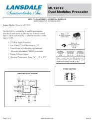
Freescale Semiconduc<strong>to</strong>r, Inc.Application Note<strong>MC145051</strong> ADCnc...Freescale Semiconduc<strong>to</strong>r, ISuccessiveApproximationThe <strong>MC145051</strong> is a ratiometric 10-bit ADC providing 11 analog channelsof conversion with an internal sample-and-hold. The <strong>MC145051</strong> has aninternal resis<strong>to</strong>r capaci<strong>to</strong>r (RC) clock oscilla<strong>to</strong>r <strong>to</strong> run its internal digitalcircuitry. The maximum conversion time for <strong>the</strong> <strong>MC145051</strong> is 44 µs witha maximum sample rate of 21.4 ksamples/s. If faster conversion time isneeded, an MC145050 can be used that is <strong>the</strong> same as <strong>the</strong> <strong>MC145051</strong>except it requires an external clock. With a 2.1-MHz clock, <strong>the</strong>MC145050 provides a 21 µs conversion time and a maximum samplerate of 38 ksamples/s. The <strong>MC145051</strong> operates with a single voltagesupply between 4.5 and 5.5 volts. A serial interface is used <strong>to</strong> receive <strong>the</strong>channel address <strong>to</strong> convert and transmit converted values <strong>to</strong> <strong>the</strong> outsideworld.The <strong>MC145051</strong> utilizes successive approximation <strong>to</strong> convert <strong>the</strong> analoginput signal <strong>to</strong> a digital value. This technique consists of comparing <strong>the</strong>unknown analog input <strong>to</strong> a known analog voltage created by a digital-<strong>to</strong>analogconverter (DAC). The digital number given <strong>to</strong> <strong>the</strong> DAC is <strong>the</strong>number that will eventually be <strong>the</strong> result of <strong>the</strong> ADC's output. Thisprocess of "guessing" <strong>the</strong> analog input voltage is similar <strong>to</strong> weighing witha balance. If you had three weights consisting of 1/2, 1/4, and 1/8 of agram, you could measure something up <strong>to</strong> 1 gram within ±1/16 gram of<strong>the</strong> weight. One side of <strong>the</strong> scale would hold <strong>the</strong> unknown and <strong>the</strong> o<strong>the</strong>rside would contain various weights "guessing" at <strong>the</strong> weighted value of<strong>the</strong> unknown.Consider how a 3-bit A/D converter would convert an unknown signal.Figure 1 shows <strong>the</strong> block diagram of a very simple 3-bit A/D converter.A digital number is fed in<strong>to</strong> <strong>the</strong> DAC and <strong>the</strong> DAC converts this <strong>to</strong> ananalog voltage for <strong>the</strong> compara<strong>to</strong>r <strong>to</strong> use. If <strong>the</strong> input analog voltage islarger than <strong>the</strong> DAC's output voltage, a 1 is <strong>the</strong> result of <strong>the</strong> comparison.If <strong>the</strong> input analog voltage is smaller than <strong>the</strong> DAC's output, a 0 is <strong>the</strong>result of <strong>the</strong> comparison. The result of <strong>the</strong> comparison is fed back in<strong>to</strong><strong>the</strong> successive approximation register. The control logic adds a smallerdigitally "weighted" value <strong>to</strong> <strong>the</strong> DAC <strong>to</strong> "guess" at <strong>the</strong> input analogAN1228 — Rev. 2.02 MOTOROLAFor More Information On This Product,Go <strong>to</strong>: www.freescale.com
Freescale Semiconduc<strong>to</strong>r, Inc.Application Note<strong>MC145051</strong> ADCvoltage. This sequence continues until <strong>the</strong> smallest digital "weight" isused <strong>to</strong> guess at <strong>the</strong> input voltage. Figure 2 illustrates thisCOMPARATORANALOG INPUT+–ANALOG REFERENCE3-BIT DACDIGITAL OUTPUTnc...START CONVERSIONCLOCKSHIFT REGISTERCONTROL LOGICOUTPUT REGISTERCONVERSION OUTPUTFreescale Semiconduc<strong>to</strong>r, IaDIGITAL OUTPUTBINARY AND FRACTIONAL17/86/85/84/83/82/81/80Figure 1. Simple 3-Bit A/D <strong>Converter</strong>111110101100011010001000TESTMSBMSBANSWERTESTBIT 1ANALOG INPUT VOLTAGE0 1 1BIT 1ANSWERTESTLSBLSBANSWERTIMEFigure 2. 3-Bit A/D Weighing SequenceAN1228 — Rev. 2.0MOTOROLA 3For More Information On This Product,Go <strong>to</strong>: www.freescale.com
Freescale Semiconduc<strong>to</strong>r, Inc.Application Notenc...Freescale Semiconduc<strong>to</strong>r, IInside <strong>the</strong><strong>MC145051</strong>process with a graph that depicts <strong>the</strong> testing of a signal of magnitudebetween 3/8 and 4/8 of <strong>the</strong> full scale analog reference voltage. After <strong>the</strong>guesswork is done, <strong>the</strong> binary answer of 011 is written <strong>to</strong> an outputregister for fur<strong>the</strong>r processing.In this example, <strong>the</strong> input voltage does not change over <strong>the</strong> entireconversion process. We have assumed that <strong>the</strong> signal does not changeand <strong>the</strong>re is no noise <strong>to</strong> change <strong>the</strong> input voltage. In most cases asample-and-hold circuit is used <strong>to</strong> sample a voltage signal and hold it fora specific length of time until <strong>the</strong> conversion process is complete.The accuracy, linearity, and speed of <strong>the</strong> successive approximating A/Dconverter are dependent on <strong>the</strong> properties of <strong>the</strong> DAC and <strong>the</strong>compara<strong>to</strong>r. The settling time of <strong>the</strong> DAC and <strong>the</strong> speed of <strong>the</strong>compara<strong>to</strong>r determine <strong>the</strong> speed of <strong>the</strong> conversion process. Likewise, if<strong>the</strong> conversion demands more resolution, <strong>the</strong> time <strong>to</strong> convert will beleng<strong>the</strong>ned. The DAC's non-linearity will result in non-linearities within<strong>the</strong> ADC. All of <strong>the</strong>se fac<strong>to</strong>rs affect <strong>the</strong> digital output result of <strong>the</strong> ADC.As stated earlier, <strong>the</strong> <strong>MC145051</strong> will convert one of <strong>the</strong> 11 analog inputsin<strong>to</strong> a 10-bit digital representation of <strong>the</strong> analog signal. The 10-bit digitalvalue is transmitted <strong>to</strong> <strong>the</strong> outside world via a serial bus. Figure 3 showsa block diagram of <strong>the</strong> <strong>MC145051</strong>. The sequence of starting aconversion, converting <strong>the</strong> voltage, and transmitting <strong>the</strong> result is:1. The CS signal is driven low <strong>to</strong> initialize <strong>the</strong> serial port that a 4-bitaddress is going <strong>to</strong> be received and <strong>the</strong> previous 10-bit digitalresult will be transmitted.2. After <strong>the</strong> 4-bit mux address is received in <strong>the</strong> mux addressregister, one of <strong>the</strong> analog inputs is selected from <strong>the</strong> analogmultiplexer. This signal is sent <strong>to</strong> <strong>the</strong> sample-and-hold <strong>to</strong> start <strong>the</strong>10-bit conversion process.3. While <strong>the</strong> 4-bit address is received, <strong>the</strong> 10-bit previouslyconverted value is sent out on <strong>the</strong> D OUT pin.4. The internal clock drives <strong>the</strong> digital control circuitry, which in turnmanipulates <strong>the</strong> successive approximation register until <strong>the</strong> 10-bitconversion is complete.AN1228 — Rev. 2.04 MOTOROLAFor More Information On This Product,Go <strong>to</strong>: www.freescale.com
Freescale Semiconduc<strong>to</strong>r, Inc.Application Note<strong>MC145051</strong> ADC5. Once <strong>the</strong> conversion is complete, <strong>the</strong> final value of <strong>the</strong> successiveapproximation register is written <strong>to</strong> <strong>the</strong> data register. The 10-bitresult will stay here until it is queued <strong>to</strong> be sent out on <strong>the</strong> D OUT pinon <strong>the</strong> next serial transmission. Also, <strong>the</strong> <strong>MC145051</strong> will signal <strong>the</strong>ending of a conversion by driving <strong>the</strong> end-of-conversion (EOC) pinhigh. In some transmission scenarios, <strong>the</strong> CS pin must be negatedhigh before ano<strong>the</strong>r transmission and conversion can occur.V REF V AGD OUTnc...Freescale Semiconduc<strong>to</strong>r, IAN0AN1AN2AN3AN4AN5AN6AN7AN8AN9AN10ANALOGMUX10-BIT DACMUX ADDRESSREGISTERINTERNAL RCCLOCK OSCFigure 3. <strong>MC145051</strong> Block Diagram+–DIGITALCONTROLCOMPARATOR& SAMPLE/HOLDSUCCESSIVEAPPROXIMATIONREGISTERDATA REGISTER(<strong>MC145051</strong> ONLY)(MC145050 ONLY)D INCSSCLKEOCADCLKAN1228 — Rev. 2.0MOTOROLA 5For More Information On This Product,Go <strong>to</strong>: www.freescale.com
Freescale Semiconduc<strong>to</strong>r, Inc.Application NoteAnalog InterfaceThe analog input consists of <strong>the</strong> converter's high and low voltagereference pins and all 11 analog input pins. The analog specificationsare listed in Table 1.Table 1. Analog SpecificationsSymbol Parameter Min MaxV REF DC Reference Voltage V AG +4.0 V DD +0.1V AG Analog Ground V SS –0.1 V REF –4.0nc...Freescale Semiconduc<strong>to</strong>r, IV AI Analog Input Voltage V AG V REFThe <strong>MC145051</strong> will take <strong>the</strong> voltage it samples off its analog input pinand convert it <strong>to</strong> a number equivalent <strong>to</strong> <strong>the</strong> ratio of <strong>the</strong> input voltage and<strong>the</strong> difference between <strong>the</strong> V REF and V AG . This number is <strong>the</strong> converter'sdigital representation of <strong>the</strong> sampled voltage input. Figure 4 illustratesthis ratio and describes an equation that predicts <strong>the</strong> ADC's conversionvalue. For example, if V AI = 2.34 volts, <strong>the</strong>n <strong>the</strong> 10-bit representation ofthat voltage is 479 or $1DF.V REFV AIV AGV AIV REF –V AG=V AIFigure 4. A/D Conversion Ratio?102 –1x 1023 = ?V REF –V AGAN1228 — Rev. 2.06 MOTOROLAFor More Information On This Product,Go <strong>to</strong>: www.freescale.com
Freescale Semiconduc<strong>to</strong>r, Inc.Application Note<strong>MC145051</strong> ADCDigital InterfaceThe digital interface <strong>to</strong> <strong>the</strong> <strong>MC145051</strong> is composed of a serial data portthat synchronously transceives data. Each digital pin's function isexplained here.CSActive-Low Chip SelectWhen asserted low, this pin initializes <strong>the</strong> chip <strong>to</strong> start performingA/D conversions. While high, <strong>the</strong> D OUT pin is forced <strong>to</strong> a highimpedancestate and <strong>the</strong> D IN pin is disabled.nc...Freescale Semiconduc<strong>to</strong>r, ID OUTD INSerial Data OutThis pin serves as <strong>the</strong> serial output data of <strong>the</strong> A/D conversionresult. After CS is asserted low, D OUT is driven with <strong>the</strong> mostsignificant bit of <strong>the</strong> previous 10-bit A/D result. The value of D OUTchanges <strong>to</strong> <strong>the</strong> second most significant bit after <strong>the</strong> falling edge of<strong>the</strong> serial clock (SCLK). After 10 bits of transmission, D OUT isdriven low. The A/D result is always driven out of D OUT mostsignificant bit (MSB) first.Serial Data InThis pin serves as <strong>the</strong> input data line that receives <strong>the</strong> 4-bitaddress of <strong>the</strong> serial stream. The address is shifted on <strong>the</strong> risingedge of SCLK with <strong>the</strong> MSB being <strong>the</strong> first bit received. After allfour bits have been received, <strong>the</strong> D IN pin is ignored.SCLK Serial Data ClockThis pin is an input that drives <strong>the</strong> serial transmission lines. Itdrives <strong>the</strong> data shift registers so that <strong>the</strong> next mux address isreceived and <strong>the</strong> previous conversion is driven out.EOCEnd-of-Conversion OutputThis pin is driven low on <strong>the</strong> 10th falling edge of SCLK. A low-<strong>to</strong>hightransition on EOC occurs after <strong>the</strong> A/D conversion iscomplete.AN1228 — Rev. 2.0MOTOROLA 7For More Information On This Product,Go <strong>to</strong>: www.freescale.com
Freescale Semiconduc<strong>to</strong>r, Inc.Application NoteThe <strong>MC145051</strong> is capable of various bit stream formats. The timingdiagram used in this application note is shown in Figure 5. The<strong>MC145051</strong> will wait patiently until its CS pin is asserted low. Thissignifies that a serial clock will be driving <strong>the</strong> SCLK pin <strong>to</strong> transfer <strong>the</strong>next A/D channel address <strong>to</strong> be converted. At <strong>the</strong> same time, <strong>the</strong><strong>MC145051</strong> will be driving out <strong>the</strong> converted value of <strong>the</strong> previousconversion. After <strong>the</strong> 10-bit address is driven out of D OUT , <strong>the</strong> CS pin willbe driven high <strong>to</strong> signify <strong>the</strong> end of <strong>the</strong> transmission process.nc...Freescale Semiconduc<strong>to</strong>r, ICS16SCLK1 2 3 4 5 6 7 8 9 10 11DOUTD9 D8 D7 D6 D5 D4 D3 D2 D1 D0 LEVELDINA3 A2 A1 A0LOW H IGH ZFigure 5. <strong>MC145051</strong> Timing DiagramAN1228 — Rev. 2.08 MOTOROLAFor More Information On This Product,Go <strong>to</strong>: www.freescale.com
Freescale Semiconduc<strong>to</strong>r, Inc.Application NoteDescription of <strong>the</strong> MC68HC705C8 InterfaceDescription of <strong>the</strong> MC68HC705C8 InterfaceThe following paragraphs describe <strong>the</strong> MC68HC705C8 interface.nc...Freescale Semiconduc<strong>to</strong>r, IHardwareThe MC68HC705C8 is one of <strong>the</strong> most popular members of <strong>the</strong><strong>M68HC05</strong> Family of 8-bit <strong>MCU</strong>s. It has <strong>the</strong> serial peripheral interface(SPI) that will be used <strong>to</strong> interface <strong>to</strong> <strong>the</strong> <strong>MC145051</strong>. The SPI is, inessence, an 8-bit serial shift register that can be manipulated bysoftware instructions. The SPI can be programmed with different clockpolarities and clock phases <strong>to</strong> correctly communicate with a number ofdevices. The SPI can also be configured <strong>to</strong> act as a master or a slave.Each signal of <strong>the</strong> SPI is explained below. For more detail on <strong>the</strong> SPI,consult MC68HC705C8 Technical Data, Rev. 1 (MC68HC705C8/D).SCKSerial Data ClockThe SCK signal is used <strong>to</strong> synchronize <strong>the</strong> movement of data inand out of <strong>the</strong> SPI module. This pin is an output or an inputdependent on whe<strong>the</strong>r <strong>the</strong> SPI is configured as a master or aslave. Data is shifted on one side of <strong>the</strong> clock edge and sampledon <strong>the</strong> o<strong>the</strong>r. The SCK signal can be configured <strong>to</strong> accommodatedifferent serial peripheral bus structures.MOSI Master Output, Slave InputWhen <strong>the</strong> SPI is configured as a master, this pin is used as anoutput <strong>to</strong> shift <strong>the</strong> 8-bit serial data out with <strong>the</strong> most significant bit(MSB) first. The pin is used as a slave data input when <strong>the</strong> SPI isconfigured as a slave.MISO Master Input, Slave OutputIf <strong>the</strong> SPI is configured as a master, this pin is utilized as an input.When <strong>the</strong> SPI is in slave mode, <strong>the</strong> pin is used as an output.SSSlave SelectWhen <strong>the</strong> SPI is a slave, this pin enables <strong>the</strong> SPI for an incomingtransfer. As a master, this pin should be tied high.To correctly interface <strong>to</strong> <strong>the</strong> <strong>MC145051</strong>, <strong>the</strong> SPI is configured as amaster with <strong>the</strong> timing diagram shown in Figure 6. This configurationAN1228 — Rev. 2.0MOTOROLA 9For More Information On This Product,Go <strong>to</strong>: www.freescale.com
Freescale Semiconduc<strong>to</strong>r, Inc.Application Noteenables <strong>the</strong> SCK <strong>to</strong> drive out data with <strong>the</strong> MOSI pin on <strong>the</strong> rising edgeand receive data with <strong>the</strong> MISO pin on <strong>the</strong> falling edge.SCK1 2 3 4 5 6 7 8MOSI MSB 6 5 4 3 2 1 LSBMISO MSB 6 5 4 3 2 1 LSBnc...Freescale Semiconduc<strong>to</strong>r, IFigure 6. SPI Timing DiagramThe schematic used for this interface is shown in Appendix A —MC68HC705C8/<strong>MC145051</strong> Schematic. The MC68HC705C8 is clockedby a 4-MHz crystal circuit. This provides <strong>the</strong> <strong>MCU</strong> with a 2-MHz internalbus frequency and a 500-ns bus period or instruction cycle. TheMC34064 is used as a low-voltage inhibi<strong>to</strong>r circuit. This 3-pin, T0-92device ensures that <strong>the</strong> reset pin is pulled low if <strong>the</strong> operating voltage <strong>to</strong><strong>the</strong> <strong>MCU</strong> falls below 4.6 volts.The SPI lines are connected <strong>to</strong> <strong>the</strong> appropriate pins on <strong>the</strong> <strong>MC145051</strong>.The MOSI pin drives data out of <strong>the</strong> MC68HC705C8 and in<strong>to</strong> <strong>the</strong> D IN pinof <strong>the</strong> <strong>MC145051</strong>. The D OUT pin drives data out of <strong>the</strong> <strong>MC145051</strong> pin in<strong>to</strong><strong>the</strong> MISO pin of <strong>the</strong> MC68HC705C8. Since <strong>the</strong> SPI is configured as amaster, <strong>the</strong> SCK pin is driving <strong>the</strong> SCLK pin of <strong>the</strong> <strong>MC145051</strong> and <strong>the</strong>SS pin is tied high.The MC68HC705C8 is programmed <strong>to</strong> utilize <strong>the</strong> SPI <strong>to</strong> read <strong>the</strong><strong>MC145051</strong>. Channel AN0 of <strong>the</strong> <strong>MC145051</strong> is used <strong>to</strong> read <strong>the</strong> voltagecreated by <strong>the</strong> 10 kΩ potentiometer between <strong>the</strong> V REF and <strong>the</strong> V AG levels.A 0.22 µF capaci<strong>to</strong>r is used between <strong>the</strong> V REF and V AG pins <strong>to</strong> filter outhigh frequency noise. This capaci<strong>to</strong>r should be mounted as close <strong>to</strong> <strong>the</strong><strong>MC145051</strong> as possible. After <strong>the</strong> MC68HC705C8 receives <strong>the</strong> data from<strong>the</strong> <strong>MC145051</strong>, it is driven out on<strong>to</strong> ports B and C of <strong>the</strong> MC68HC705C8.The circuit given in Appendix A — MC68HC705C8/<strong>MC145051</strong>Schematic minimizes <strong>the</strong> noise often found in emulated systems.Instead of programming <strong>the</strong> MC68HC705C8, <strong>the</strong> <strong>M68HC05</strong>EVM can beused <strong>to</strong> emulate <strong>the</strong> MC68HC705C8. This evaluation module will notgive as accurate an A/D reading as <strong>the</strong> circuit in Appendix A —AN1228 — Rev. 2.010 MOTOROLAFor More Information On This Product,Go <strong>to</strong>: www.freescale.com
Freescale Semiconduc<strong>to</strong>r, Inc.Application NoteDescription of <strong>the</strong> MC68HC705C8 InterfaceMC68HC705C8/<strong>MC145051</strong> Schematic, but allows more flexibility incode development than using a programmed MC68HC705C8.nc...Freescale Semiconduc<strong>to</strong>r, ISoftwareThe flowchart for <strong>the</strong> SPI-driven <strong>MC145051</strong> is shown inAppendix B — MC68HC705C8/<strong>MC145051</strong> Flowchart, and <strong>the</strong> actual<strong>M68HC05</strong> assembly code is given in Appendix C —MC68HC705C8/<strong>MC145051</strong> Assembly Code. This code was written fora programmed MC68HC705C8. Extra lines of code were added so that<strong>the</strong> routine would perform in a standalone application.For <strong>the</strong> SPI <strong>to</strong> "talk" <strong>to</strong> <strong>the</strong> <strong>MC145051</strong>, <strong>the</strong> SPI must be configured <strong>to</strong>match up with <strong>the</strong> <strong>MC145051</strong> timing diagram, as shown earlier in Figure5. Also, two SPI transmissions must be sent <strong>to</strong> form a 16-bit transfer.Before any transmissions can start, <strong>the</strong> CS pin must be asserted low.This initializes <strong>the</strong> <strong>MC145051</strong> and tells it that a new mux address will besent <strong>to</strong> it <strong>to</strong> start <strong>the</strong> conversion process. The first transfer sends <strong>the</strong> A/Dchannel number <strong>to</strong> <strong>the</strong> <strong>MC145051</strong>, and <strong>the</strong> <strong>MC145051</strong> sends <strong>the</strong> uppereight bits of <strong>the</strong> previously converted value. These eight bits are written<strong>to</strong> <strong>the</strong> MSB of <strong>the</strong> 16-bit result register and <strong>to</strong> port B. The second transfersends <strong>the</strong> A/D channel <strong>to</strong> <strong>the</strong> <strong>MC145051</strong> but <strong>the</strong> <strong>MC145051</strong> ignores itbecause it is not needed. The <strong>MC145051</strong> sends <strong>the</strong> 705C8 <strong>the</strong> two leastsignificant bits (LSB) from <strong>the</strong> previously converted value. These two bitsare <strong>the</strong> two most significant bits in <strong>the</strong> received SPI data. This byte iswritten <strong>to</strong> <strong>the</strong> LSB of <strong>the</strong> 16-bit result register and <strong>to</strong> port C. After bothtransmissions are done, CS is negated high. Port B and port C now have<strong>the</strong> 10-bit A/D value of <strong>the</strong> previous conversion. This output value on portB and port C is illustrated in Figure 7. The routine will now sit in aninfinite loop waiting for a reset.10-BIT RESULT = $1C2 = 01,1100,0010%PORT B = $70 = 0111,0000%PORT C = $80 = 1000,0000%PB7PB6PB5PB4PB3PB2PB1PB0PC7PC6PC5PC4PC3PC2PC1PC00 1 1 1 0 0 0 0 1 0 0 0 0 0 0 0Figure 7. A/D Value on Port B and Port CAN1228 — Rev. 2.0MOTOROLA 11For More Information On This Product,Go <strong>to</strong>: www.freescale.com
Freescale Semiconduc<strong>to</strong>r, Inc.Application NoteThe following example is provided <strong>to</strong> test <strong>the</strong> software routine. Follow<strong>the</strong>se steps after programming <strong>the</strong> MC68HC705C8 with <strong>the</strong> code inAppendix C — MC68HC705C8/<strong>MC145051</strong> Assembly Code andconstructing <strong>the</strong> schematic in Appendix A —MC68HC705C8/<strong>MC145051</strong> Schematic.1. Set <strong>the</strong> potentiometer <strong>to</strong> a reading of 2.20 volts.2. If V REF –V AG is exactly 5.00 volts, <strong>the</strong> A/D should convert <strong>to</strong> areading of 450 or $1C2. (See Figure 4.)nc...Freescale Semiconduc<strong>to</strong>r, I3. Power on <strong>the</strong> circuit.4. The A/D value will be outputted on port B and port C. This value is<strong>the</strong> previously converted value. Since <strong>the</strong>re was no previousconversion, <strong>the</strong> data will be garbage.5. Pull <strong>the</strong> RESET pin low and <strong>the</strong>n high. The routine will run again,and <strong>the</strong> previous value of <strong>the</strong> AN0 channel conversion isrepresented on port B and port C. The value for port B should be$70 and port C should be $80. The result might differ by a leastsignificant bit (LSB). (See Figure 7.)This routine is <strong>the</strong> simplest example <strong>to</strong> test and learn <strong>the</strong> interface from<strong>the</strong> MC68HC705C8 <strong>to</strong> <strong>the</strong> <strong>MC145051</strong>. Notice that <strong>the</strong> mux address mustbe in <strong>the</strong> high nibble of <strong>the</strong> byte before it is written <strong>to</strong> <strong>the</strong> SPI dataregister. Also, since this routine was hard-coded, <strong>the</strong> A/D channel wasalready known and written in<strong>to</strong> memory. The code can be easily adaptedas a subroutine, which requires that <strong>the</strong> channel <strong>to</strong> be converted is aninput <strong>to</strong> <strong>the</strong> subroutine. If <strong>the</strong> application requires that successive A/Dconversions are made, make sure that <strong>the</strong> <strong>MC145051</strong> has enough time<strong>to</strong> convert <strong>the</strong> present channel before initializing ano<strong>the</strong>r conversion. Ifneeded, <strong>the</strong> <strong>MC145051</strong> provides <strong>the</strong> EOC pin. During a conversionprocess, <strong>the</strong> pin is held low. After conversion is complete, <strong>the</strong> pin isdriven high. Ano<strong>the</strong>r port pin on <strong>the</strong> MC68HC705C8 might be used <strong>to</strong>read <strong>the</strong> EOC pin.AN1228 — Rev. 2.012 MOTOROLAFor More Information On This Product,Go <strong>to</strong>: www.freescale.com
Freescale Semiconduc<strong>to</strong>r, Inc.Application NoteDescription of <strong>the</strong> MC68HC705K1 InterfaceDescription of <strong>the</strong> MC68HC705K1 InterfaceThe following paragraphs describe <strong>the</strong> MC68HC705K1 interface.nc...Freescale Semiconduc<strong>to</strong>r, IHardwareWith only 16 pins, <strong>the</strong> MC68HC705K1 is one of <strong>the</strong> smallest membersof <strong>the</strong> <strong>M68HC05</strong> Family. It has a <strong>to</strong>tal of 504 bytes of erasableprogrammable read-only memory (EPROM) and includes 10input/output (I/O) pins. The schematic for <strong>the</strong> MC68HC705K1 <strong>to</strong><strong>MC145051</strong> interface is shown in Appendix D —MC68HC705K1/<strong>MC145051</strong> Schematic. With this interface, <strong>the</strong>M68HC705KICS development board was used <strong>to</strong> write and test <strong>the</strong>code. The circuitry surrounding <strong>the</strong> <strong>MC145051</strong> is <strong>the</strong> same as in <strong>the</strong>MC68HC705C8 design. The only changes are <strong>the</strong> serial pins of <strong>the</strong><strong>MC145051</strong>. These pins are connected <strong>to</strong> <strong>the</strong> emulation header of <strong>the</strong>M68HC705KICS board. This emulation header has <strong>the</strong> exact pinout of<strong>the</strong> MC68HC705K1. The pins used <strong>to</strong> drive <strong>the</strong> <strong>MC145051</strong> on <strong>the</strong>MC68HC705K1 are:• Port A, Bit 0 This I/O pin (CS) is configured as an output <strong>to</strong>drive <strong>the</strong> CS pin on <strong>the</strong> <strong>MC145051</strong>.• Port A, Bit 1 This I/O pin (SER_CLK) is configured as an output<strong>to</strong> drive <strong>the</strong> serial clock of <strong>the</strong> serial transmissionbus.• Port A, Bit 2 This I/O pin (SER_OUT) is configured as an output<strong>to</strong> drive <strong>the</strong> serial data out and in<strong>to</strong> <strong>the</strong> D IN pin of <strong>the</strong>5051.• Port A, Bit 3 This I/O pin (SER_IN) is configured as an input <strong>to</strong>receive data driven from pin D OUT of <strong>the</strong><strong>MC145051</strong>.The emulation test circuit may also be configured as a standalonedesign. For fur<strong>the</strong>r information on programming <strong>the</strong> MC68HC705K1,consult <strong>the</strong> MC68HC705K1 Technical Data, Rev. 1 (MC68HC705K1/D)and <strong>the</strong> M68HC705KICS development board documentation.AN1228 — Rev. 2.0MOTOROLA 13For More Information On This Product,Go <strong>to</strong>: www.freescale.com
Freescale Semiconduc<strong>to</strong>r, Inc.Application NoteSoftwareThe flowchart for <strong>the</strong> bit-banged-driven <strong>MC145051</strong> is shown inAppendix E — MC68HC705K1/<strong>MC145051</strong> Flowchart, and <strong>the</strong> actual<strong>M68HC05</strong> assembly code is given in Appendix F —MC68HC705K1/<strong>MC145051</strong> Assembly Code. Bit-banging is <strong>the</strong>process of <strong>to</strong>ggling I/O pins with software instructions <strong>to</strong> emulate acertain piece of hardware peripheral. This bit-banged routine was writtenespecially for <strong>the</strong> <strong>MC145051</strong>. It is not a full featured representation of <strong>the</strong>MC68HC705C8 SPI module. Enhancements <strong>to</strong> <strong>the</strong> routine were notincluded <strong>to</strong> maximize <strong>the</strong> efficiency of <strong>the</strong> code.nc...Freescale Semiconduc<strong>to</strong>r, IAs stated in <strong>the</strong> preceding Hardware section, I/O pins have been used<strong>to</strong> send out <strong>the</strong> correct serial transmission pro<strong>to</strong>col <strong>to</strong> <strong>the</strong> <strong>MC145051</strong>.The <strong>M68HC05</strong> CPU provides special instructions <strong>to</strong> specificallymanipulate single I/O pins. The <strong>MC145051</strong> serial stream shown inFigure 5 will be re-created by four I/O pins on <strong>the</strong> MC68HC705K1.The best way <strong>to</strong> describe <strong>the</strong> code is <strong>to</strong> list each segment of <strong>the</strong> codeand explain its purpose <strong>to</strong> bit-bang <strong>the</strong> <strong>MC145051</strong>. PA2 is shorthand forport A, bit 2.EquivalentsPA0 = CSPA1 = SER_CLKPA2 = SER_OUTPA3 = SER_INInitialize Port ACS = 1 ⇒ outputSER_CLK = 0 ⇒ outputSER_OUT = 0 ⇒ outputSER_IN = 0 ⇒ inputBegin A/D AcquisitionThe CS pin is driven low <strong>to</strong> start <strong>the</strong> serial transmission.The CHANNEL RAM byte is read. The address is in <strong>the</strong> low nibble of<strong>the</strong> byte. The 16-bit RESULT registers are cleared and a copy ofCHANNEL is s<strong>to</strong>red in TMP_CHN for future use. When emulating,make sure that location $E2 is initialized with <strong>the</strong> A/D channel $00.AN1228 — Rev. 2.014 MOTOROLAFor More Information On This Product,Go <strong>to</strong>: www.freescale.com
Freescale Semiconduc<strong>to</strong>r, Inc.Application NoteDescription of <strong>the</strong> MC68HC705K1 InterfaceInitialize Loop1Set <strong>the</strong> index register <strong>to</strong> 4.nc...Freescale Semiconduc<strong>to</strong>r, IRead <strong>the</strong> serial input pin — Start of Loop 1The branch-if-clear instruction is used <strong>to</strong> read SER_IN. The purposeof this is <strong>to</strong> transfer <strong>the</strong> logic state on <strong>the</strong> SER_IN pin <strong>to</strong> <strong>the</strong> carry bit(C). No branch is taken. The next line of code is always executed.Two rotate left instructions rotate <strong>the</strong> C bit in<strong>to</strong> <strong>the</strong> 16-bit RESULTregister composed of RESULT and RESULT+1. The first bit read onSER_IN is <strong>the</strong> MSB of <strong>the</strong> previous A/D result from <strong>the</strong> <strong>MC145051</strong>.Write <strong>the</strong> serial output pinThe TMP_CHN is rotated left. Bit 4 of TMP_CHN is read. If it is high,a 1 is written <strong>to</strong> SER_OUT. If it is low, a 0 is written <strong>to</strong> SER_OUT. Thisfirst transmitted bit is <strong>the</strong> MSB of <strong>the</strong> 4-bit A/D channel address.Clock <strong>the</strong> serial clock pinThe SER_CLK pin is written high and <strong>the</strong>n written low.Is Loop 1 done?The index register is decremented and checked <strong>to</strong> see if it is 0. If IX isnot 0, <strong>the</strong> code is executed at <strong>the</strong> start of Loop 1. This loop continuesuntil four transmissions are completed.Initialize Loop 2Set <strong>the</strong> index register <strong>to</strong> 6.Read <strong>the</strong> serial input pin — Start of Loop 2This is <strong>the</strong> same code that was executed at <strong>the</strong> start of loop 1 above.Notice that loop 2 does not transmit any more bits on SER_OUT. Thisis because <strong>the</strong> <strong>MC145051</strong> ignores <strong>the</strong> last six transmitted bitsbecause it has already received <strong>the</strong> four address bits it needs.Clock <strong>the</strong> serial clock pinThe SER_CLK pin is written high and <strong>the</strong>n written low.AN1228 — Rev. 2.0MOTOROLA 15For More Information On This Product,Go <strong>to</strong>: www.freescale.com
Freescale Semiconduc<strong>to</strong>r, Inc.Application NoteIs Loop 2 done?The index register is decremented and checked <strong>to</strong> see if it is 0. If IX isnot 0, <strong>the</strong> code is executed at <strong>the</strong> start of Loop 2. This loop continuesuntil six transmissions are completed.Negate CSA 1 is written <strong>to</strong> <strong>the</strong> CS. This completes <strong>the</strong> serial transmission <strong>to</strong> <strong>the</strong><strong>MC145051</strong>.nc...Freescale Semiconduc<strong>to</strong>r, ILayout ConsiderationsSince this code was written for emulation on <strong>the</strong> M68HC705KICS board,it is easy <strong>to</strong> experiment with different applications. The code can beeasily adapted <strong>to</strong> fit any cus<strong>to</strong>m application that needs 10-bit A/D data.There are many things <strong>to</strong> consider when laying out mixed signal designssuch as <strong>the</strong> <strong>MC145051</strong> and <strong>the</strong> <strong>M68HC05</strong> <strong>MCU</strong>. The accuracy of <strong>the</strong><strong>MC145051</strong> may be greatly affected if proper layout design is notfollowed. Listed here are some things <strong>to</strong> check <strong>to</strong> ensure <strong>the</strong> accuracyof your A/D converter. For more in-depth study of ADC layout issues,consult Reducing A/D Errors in Microcontroller Applications(AN1058/D).• Physically separate critical analog circuits from <strong>the</strong> digital circuitsof <strong>the</strong> <strong>MCU</strong>. If possible, split your board in half <strong>to</strong> separate analogand digital circuits. Each half will have its own power and groundsystem.• Do not let analog input line traces cross digital traces. If this has <strong>to</strong>happen, make sure <strong>the</strong>y cross at right angles <strong>to</strong> each o<strong>the</strong>r.• Use power or ground traces <strong>to</strong> isolate <strong>the</strong> analog-input pins from<strong>the</strong> digital pins.• Bypass <strong>the</strong> power supplies <strong>to</strong> <strong>the</strong> proper ground at <strong>the</strong> <strong>MC145051</strong>power pins with quality ceramic capaci<strong>to</strong>rs. Keep <strong>the</strong> bypasscapaci<strong>to</strong>rs lead lengths as short as possible.AN1228 — Rev. 2.016 MOTOROLAFor More Information On This Product,Go <strong>to</strong>: www.freescale.com
Freescale Semiconduc<strong>to</strong>r, Inc.Application NoteReferences/Fur<strong>the</strong>r Reading• To bypass low frequency power supply noise, use tantalum oraluminum electrolytic capaci<strong>to</strong>rs of 5 <strong>to</strong> 20 µF. These should beplaced near <strong>the</strong> point where <strong>the</strong> power supplies enter <strong>the</strong> board.References/Fur<strong>the</strong>r ReadingAnalog-Digital Conversion Handbook, Third Edition, New York:Prentice-Hall, 1986.nc...Freescale Semiconduc<strong>to</strong>r, IMC145050/51 Technical Data Sheet, (MC145050/D), Mo<strong>to</strong>rola, 1993.MC68HC05 Applications Guide, (<strong>M68HC05</strong>AG/AD), Mo<strong>to</strong>rola, 1989.MC68HC705C8 Technical Data, (MC68HC705C8/D), Mo<strong>to</strong>rola, 1990.MC68HC705K1 Technical Data, (MC68HC705K1/D), Mo<strong>to</strong>rola, 1993.Reducing A/D Errors in Microcontroller Applications, (AN1058/D),Mo<strong>to</strong>rola, 1990.AN1228 — Rev. 2.0MOTOROLA 17For More Information On This Product,Go <strong>to</strong>: www.freescale.com
Freescale Semiconduc<strong>to</strong>r, Inc.Application NoteAppendix A — MC68HC705C8/<strong>MC145051</strong> SchematicV DD4.7 kΩ1V DDnc...Freescale Semiconduc<strong>to</strong>r, I23INPUTGNDRESETMC340644.7 kΩ1RESETV DD40234567891011IRQV PPPA7PA6PA5PA4PA3PA2PA1PA0OSC1OSC2TCAPPD7TCMPPD5/SSPD4/SCKPD3/MOSIPD2/MISOPD1/TDO3938373635343332313012PB0PD0/RDI2913PB1PC02814 27PB2PC11526PB3PC216171819PB4PB5PB6PB7PC3PC4PC5PC62524232220 V SSPC72110 kΩ4 MHz4.7 MΩ39 pF 39 pFSERIAL_CLOCKSERIAL_OUTSERIAL_INCHIP_SELECTV DDV DDMC68HC705C8SAN1228 — Rev. 2.018 MOTOROLAFor More Information On This Product,Go <strong>to</strong>: www.freescale.com
Freescale Semiconduc<strong>to</strong>r, Inc.Application NoteAppendix A — MC68HC705C8/<strong>MC145051</strong> SchematicV CC0.1 µFnc...Freescale Semiconduc<strong>to</strong>r, IGNDSERIAL_INSERIAL_OUTSERIAL_CLOCKCHIP_SELECT20101617181519V DDV SSD OUTD INSCLKCSEOCAN0AN1AN2AN3AN4AN5AN6AN7AN8AN9AN10<strong>MC145051</strong>P123456789111214V REF13V AGV DDA0.22 µFAGND10 kAN1228 — Rev. 2.0MOTOROLA 19For More Information On This Product,Go <strong>to</strong>: www.freescale.com
Freescale Semiconduc<strong>to</strong>r, Inc.Application NoteAppendix B — MC68HC705C8/<strong>MC145051</strong> FlowchartSTART"INITIALIZE PORTS"PORT A = PORT B = PORT C = $FFDATA DIR A = DATA DIR B = DATA DIR C = $FFnc...Freescale Semiconduc<strong>to</strong>r, I"INITIALIZE THE A/D CHANNEL #"CHANNEL = $00"INITIALIZE SPI MODULE"TURN ON MASTER MODECPHA = CPOL = 0"BEGIN A/D ACQUISITION"CS = 0"1ST 8-BIT SERIAL TRANSFER"LOAD ACCA UPPER NIBBLEWITH CHANNEL #STORE ACCA TO SPI DATA REGISTERTO START TRANSMISSIONIS SERIALTRANSFER DONE?NOYESAAN1228 — Rev. 2.020 MOTOROLAFor More Information On This Product,Go <strong>to</strong>: www.freescale.com
Freescale Semiconduc<strong>to</strong>r, Inc.Application NoteAppendix B — MC68HC705C8/<strong>MC145051</strong> FlowchartAREAD SPI DATA REGISTERSTORE TO RESULTSTORE TO PORT Bnc...Freescale Semiconduc<strong>to</strong>r, I"2ND 8-BIT SERIAL TRANSFER"LOAD ACCAWITH CHANNEL #STORE ACCA TO SPI DATA REGISTERTO START TRANSMISSIONIS SERIALTRANSFER DONE?READ SPI DATA REGISTERSTORE TO RESULT + 1STORE TO PORT C"END A/D ACQUISITION"CS = 1ENDYESNOAN1228 — Rev. 2.0MOTOROLA 21For More Information On This Product,Go <strong>to</strong>: www.freescale.com
Freescale Semiconduc<strong>to</strong>r, Inc.Application NoteAppendix C — MC68HC705C8/<strong>MC145051</strong> Assembly Codenc...Freescale Semiconduc<strong>to</strong>r, I******************************************************************* Program Name: C8_5051.ASM (705C8 <strong>to</strong> 145051 interface)* Revision: 1.00* Date: Oc<strong>to</strong>ber 7, 1993** Written By: Mark Glenewinkel* Mo<strong>to</strong>rola CSIC Applications** Assembled Under: P&E Microcomputer Systems IASM05** ********************************** * Revision His<strong>to</strong>ry ** *********************************** Rev 1.00 10/07/93 M.R. Glenewinkel* Initial Release******************************************************************** Program Description:** This software routine provides a way for <strong>MCU</strong>s with an* SPI module on chip <strong>to</strong> interface <strong>to</strong> <strong>the</strong> Mo<strong>to</strong>rola <strong>MC145051</strong>* 10 bit, 11 channel analog <strong>to</strong> digital converter.** This program specifically uses <strong>the</strong> MC68HC705C8 <strong>MCU</strong>* <strong>to</strong> test <strong>the</strong> code. The HC705C8 "talks" <strong>to</strong> <strong>the</strong> 5051 with* <strong>the</strong> appropriate serial data transfer from its SPI module.** For more information, please consult Mo<strong>to</strong>rola* Application Note AN1228/D.********************************************************************* Equates for 705C8 ***PORTA equ $00 ;port A data regDDRA equ $04 ;data dir reg APORTB equ $01 ;port B data regDDRB equ $05 ;data dir reg BPORTC equ $02 ;port C data regDDRC equ $06 ;data dir reg CAN1228 — Rev. 2.022 MOTOROLAFor More Information On This Product,Go <strong>to</strong>: www.freescale.com
Freescale Semiconduc<strong>to</strong>r, Inc.Application NoteAppendix C — MC68HC705C8/<strong>MC145051</strong> Assembly CodeSPCR equ $0A ;spi ctrl regSPSR equ $0B ;spi status regSPDR equ $0C ;spi data regCS equ 1 ;bit # for chip select*** RAM s<strong>to</strong>rage variables ***org $50 ;start of static RAMRESULT rmb 2 ;2 bytes needed for 10 bit resultnc...Freescale Semiconduc<strong>to</strong>r, ICHANNEL rmb 1 ;a/d channel #*** Start of program ***org $1000 ;start of programSTART lda #$FFsta PORTA ;port A = $FFsta DDRA ;port A all outputssta PORTB ;port B = $FFsta DDRB ;port B all outputssta PORTC ;port C = $FFsta DDRC ;port C all outputslda #$00 ;CHANNEL = AN0sta CHANNEL* Initialize SPI module *lda #$50 ;turn on spi, mstr modesta SPCR ;cpha=cpol=0* Send out 16 bit frame *bclr CS,PORTA ;CS* is lowlda CHANNEL ;load ACCA with CHANNEL* Send out address, receive most significant bytesta SPDR ;s<strong>to</strong>re ACCA <strong>to</strong> spi data regWAIT1 brclr 7,SPSR,WAIT1 ;wait until SPIF flag is setlda SPDR ;load ACCA with MSB of ADC resultsta RESULT ;s<strong>to</strong>re this <strong>to</strong> MSB of RESULTsta PORTB ;s<strong>to</strong>re <strong>the</strong> 8 MSBs <strong>to</strong> Port BAN1228 — Rev. 2.0MOTOROLA 23For More Information On This Product,Go <strong>to</strong>: www.freescale.com
Freescale Semiconduc<strong>to</strong>r, Inc.Application Note* Start ano<strong>the</strong>r SPI transmission <strong>to</strong> receive <strong>the</strong>* 2 least significant bitslda CHANNEL ;load ACCA with CHANNELsta SPDR ;s<strong>to</strong>re ACCA <strong>to</strong> spi data regWAIT2 brclr 7,SPSR,WAIT2 ;wait until SPIF flag is setlda SPDR ;load ACCA with LSB of ADC resultsta RESULT+1 ;s<strong>to</strong>re this <strong>to</strong> LSB of RESULTsta PORTC ;s<strong>to</strong>re <strong>the</strong> 2 LSBs <strong>to</strong> Port Cbset CS,PORTA ;CS* is high, end 16 bit framenc...Freescale Semiconduc<strong>to</strong>r, I* Wait for ever until resetFOR bra FOR ;branch <strong>to</strong> itselforg $1FFE ;define reset vec<strong>to</strong>rdw STARTAN1228 — Rev. 2.024 MOTOROLAFor More Information On This Product,Go <strong>to</strong>: www.freescale.com
Freescale Semiconduc<strong>to</strong>r, Inc.Application NoteAppendix D — MC68HC705K1/<strong>MC145051</strong> SchematicAppendix D — MC68HC705K1/<strong>MC145051</strong> SchematicV CC0.1 µFMC68HC705K1 EMULATION HEADERnc...Freescale Semiconduc<strong>to</strong>r, IPA0PA1PA2PA312345678P3161514131211109SERIAL_INSERIAL_OUTSERIAL_CLOCKCHIP_SELECTGND20101617181519V DDV SSD OUTD INSCLKCSEOCAN0AN1AN2AN3AN4AN5AN6AN7AN8AN9AN10<strong>MC145051</strong>P123456789111214V REF13V AGV DDA0.22 µFAGND10 kAN1228 — Rev. 2.0MOTOROLA 25For More Information On This Product,Go <strong>to</strong>: www.freescale.com
Freescale Semiconduc<strong>to</strong>r, Inc.Application NoteAppendix E — MC68HC705K1/<strong>MC145051</strong> FlowchartSTART"INITIALIZE PORT A"PORT A = $01PORT A DIRECTION = $07nc...Freescale Semiconduc<strong>to</strong>r, ICLEAR SER_OUT"BEGIN A/D ACQUISITION"CS = 0TMP_CHN = 0CHANNELCLEAR THE RESULT REGISTERS"INIT LOOP1 COUNTER"IX = 4"READ THE SERIAL INPUT PIN"SET CARRY BIT ACCORDING TO VALUE OF SER_INROTATE C BIT LEFT INTO RESULT REGISTERS0"WRITE THE SERIAL OUTPUT PIN"ROTATE LEFT TMP_CHNBIT #4 OFTMP_CHN?NOIX = 0?YESB1SET SER_OUT"CLOCK THE SERIAL CLOCK PIN"SET SER_CLKCLEAR SER_CLKDECREMENTIXAN1228 — Rev. 2.026 MOTOROLAFor More Information On This Product,Go <strong>to</strong>: www.freescale.com
Freescale Semiconduc<strong>to</strong>r, Inc.Application NoteAppendix E — MC68HC705K1/<strong>MC145051</strong> FlowchartB"INIT LOOP2 COUNTER"IX = 6nc...Freescale Semiconduc<strong>to</strong>r, I"READ THE SERIAL INPUT PIN"SET CARRY BIT ACCORDING TO VALUEOF SER_NROTATE C BIT LEFT INTO RESULT REGISTERNO"CLOCK THE SERIAL CLOCK PIN"SET SER_CLKCLEAR SER_CLKDECREMENT IXIX = 0?YES"END A/D ACQUISITION"CS = 1ENDAN1228 — Rev. 2.0MOTOROLA 27For More Information On This Product,Go <strong>to</strong>: www.freescale.com
Freescale Semiconduc<strong>to</strong>r, Inc.Application NoteAppendix F — MC68HC705K1/<strong>MC145051</strong> Assembly Codenc...Freescale Semiconduc<strong>to</strong>r, I******************************************************************* Program Name: K1_5051.ASM ( 705K1 <strong>to</strong> 145051 interface )* Revision: 1.00* Date: September 22, 1993** Written By: Mark Glenewinkel* Mo<strong>to</strong>rola CSIC Applications** Assembled Under: P&E Microcomputer Systems IASM05** ********************************** * Revision His<strong>to</strong>ry ** *********************************** Rev 1.00 09/22/93 M.R. Glenewinkel* Initial Release******************************************************************** Program Description:** This software routine provides a way for <strong>MCU</strong>s with no* SPI module on chip <strong>to</strong> interface <strong>to</strong> <strong>the</strong> Mo<strong>to</strong>rola <strong>MC145051</strong>* 10 bit, 11 channel analog <strong>to</strong> digital converter.** This program specifically uses <strong>the</strong> MC68HC705K1 <strong>MCU</strong> <strong>to</strong>* test <strong>the</strong> code. The HC705K1 "bit bangs" <strong>the</strong> 5051 with <strong>the</strong>* appropriate serial data transfer <strong>the</strong> 5051 understands.** For more information, please consult Mo<strong>to</strong>rola* Application Note AN1228/D.********************************************************************* Equates for 705K1 ***PORTA equ $00 ;port A data regPORTB equ $01 ;port B data regDDRA equ $04 ;data dir reg ADDRB equ $05 ;data dir reg BAN1228 — Rev. 2.028 MOTOROLAFor More Information On This Product,Go <strong>to</strong>: www.freescale.com
Freescale Semiconduc<strong>to</strong>r, Inc.Application NoteAppendix F — MC68HC705K1/<strong>MC145051</strong> Assembly CodeCS equ 0 ;bit # for chip selectSER_CLK equ 1 ;bit # for serial clockSER_OUT equ 2 ;bit # for serial data outSER_IN equ 3 ;bit # for serial data in*** RAM s<strong>to</strong>rage variables ***nc...Freescale Semiconduc<strong>to</strong>r, Iorg $E0 ;start of static RAMRESULT rmb 2 ;2 bytes needed for 10 bit resultCHANNEL rmb 1 ;a/d channel #TMP_CHN rmb 1 ;temp a/d channel for routine*** Start of program ***org $200 ;start of user eprom*** Initialization *START lda #$01 ;init port Asta PORTAlda #$07 ;init i/o of port Asta DDRA*** Init CS <strong>to</strong> low <strong>to</strong> start a/dbclr CS,PORTA ;CS* line is lowlda CHANNEL ;load ACCA with a/d channel #;(for emulation, init $E2=$00)sta TMP_CHN ;s<strong>to</strong>re ACCA <strong>to</strong> temp channelclr RESULT+1 ;clear result regsclr RESULTldx #4T ;init counter for LOOP1*** Read <strong>the</strong> serial input pinLOOP1 brclr SER_IN,PORTA,L1_1 ;carry bit = serial inL1_1 rol RESULT+1 ;rotate left resultrol RESULT*** Write <strong>the</strong> serial output pinrol TMP_CHN ;rotate left TMP_CHNbrclr 4,TMP_CHN,L1_2 ;if tmp_chn bit4 = 0, go<strong>to</strong> L1_2bset SER_OUT,PORTA ;ser_out = 1bra L1_3 ;go<strong>to</strong> L1_3L1_2 bclr SER_OUT,PORTA ;ser_out = 0AN1228 — Rev. 2.0MOTOROLA 29For More Information On This Product,Go <strong>to</strong>: www.freescale.com
Freescale Semiconduc<strong>to</strong>r, Inc.Application Note*** Clock <strong>the</strong> serial clock pinL1_3 bset SER_CLK,PORTA ;ser_clk = 1bclr SER_CLK,PORTA ;ser_clk = 0decx;decrease counter loopbne LOOP1 ;is LOOP1 finished?ldx #6T ;init counter for LOOP2nc...Freescale Semiconduc<strong>to</strong>r, I*** Read <strong>the</strong> serial input pinLOOP2 brclr SER_IN,PORTA,L2 ;carry bit = serial inL2 rol RESULT+1 ;rotate left resultrol RESULT*** Clock <strong>the</strong> serial clock pinbset SER_CLK,PORTA ;ser_clk = 1bclr SER_CLK,PORTA ;ser_clk = 0decx;decrease counter loopbne LOOP2 ;is LOOP2 finished?*** CS* high <strong>to</strong> finish serial transferbset CS,PORTA ;CS* line is highFOR BRA FOR ;branch foreverorg $03FE ;reset vec<strong>to</strong>rdw STARTAN1228 — Rev. 2.030 MOTOROLAFor More Information On This Product,Go <strong>to</strong>: www.freescale.com
Freescale Semiconduc<strong>to</strong>r, Inc.Application NoteNotesNotesFreescale Semiconduc<strong>to</strong>r, Inc...AN1228 — Rev. 2.0MOTOROLA 31For More Information On This Product,Go <strong>to</strong>: www.freescale.com
Freescale Semiconduc<strong>to</strong>r, Inc.Application Notenc...Freescale Semiconduc<strong>to</strong>r, IN O N - D I S C L O S U R E A G R E E M E N T R E Q U I R E DMo<strong>to</strong>rola reserves <strong>the</strong> right <strong>to</strong> make changes without fur<strong>the</strong>r notice <strong>to</strong> any products herein. Mo<strong>to</strong>rola makes no warranty, representation or guarantee regarding <strong>the</strong> suitability of itsproducts for any particular purpose, nor does Mo<strong>to</strong>rola assume any liability arising out of <strong>the</strong> application or use of any product or circuit, and specifically disclaims any and all liability,including without limitation consequential or incidental damages. "Typical" parameters which may be provided in Mo<strong>to</strong>rola data sheets and/or specifications can and do vary in differentapplications and actual performance may vary over time. All operating parameters, including "Typicals" must be validated for each cus<strong>to</strong>mer application by cus<strong>to</strong>mer's technical experts.Mo<strong>to</strong>rola does not convey any license under its patent rights nor <strong>the</strong> rights of o<strong>the</strong>rs. Mo<strong>to</strong>rola products are not designed, intended, or authorized for use as components in systemsintended for surgical implant in<strong>to</strong> <strong>the</strong> body, or o<strong>the</strong>r applications intended <strong>to</strong> support or sustain life, or for any o<strong>the</strong>r application in which <strong>the</strong> failure of <strong>the</strong> Mo<strong>to</strong>rola product could create asituation where personal injury or death may occur. Should Buyer purchase or use Mo<strong>to</strong>rola products for any such unintended or unauthorized application, Buyer shall indemnify and holdMo<strong>to</strong>rola and its officers, employees, subsidiaries, affiliates, and distribu<strong>to</strong>rs harmless against all claims, costs, damages, and expenses, and reasonable at<strong>to</strong>rney fees arising out of,directly or indirectly, any claim of personal injury or death associated with such unintended or unauthorized use, even if such claim alleges that Mo<strong>to</strong>rola was negligent regarding <strong>the</strong>design or manufacture of <strong>the</strong> part. Mo<strong>to</strong>rola and are registered trademarks of Mo<strong>to</strong>rola, Inc. Mo<strong>to</strong>rola, Inc. is an Equal Opportunity/Affirmative Action Employer.How <strong>to</strong> reach us:USA/EUROPE/Locations Not Listed: Mo<strong>to</strong>rola Literature Distribution; P.O. Box 5405, Denver, Colorado 80217. 1-800-441-2447 or303-675-2140Mfax: RMFAX0@email.sps.mot.com – TOUCHTONE 602-244-6609, US & Canada ONLY 1-800-774-1848INTERNET: http://mo<strong>to</strong>rola.com/spsJAPAN: Nippon Mo<strong>to</strong>rola Ltd. SPD, Strategic Planning Office 4-32-1, Nishi-Gotanda Shinagawa-ku, Tokyo 141, Japan. 81-3-5487-8488ASIA/PACIFIC: Mo<strong>to</strong>rola Semiconduc<strong>to</strong>rs H.K. Ltd.; 8B Tai Ping Industrial Park, 51 Ting Kok Road, Tai Po, N.T., Hong Kong. 852-26629298Mfax is a trademark of Mo<strong>to</strong>rola, Inc.© Mo<strong>to</strong>rola, Inc., 1997For More Information On This Product,Go <strong>to</strong>: www.freescale.comAN1228/D