Technical guide PDF - Murata
Technical guide PDF - Murata
Technical guide PDF - Murata

You also want an ePaper? Increase the reach of your titles
YUMPU automatically turns print PDFs into web optimized ePapers that Google loves.
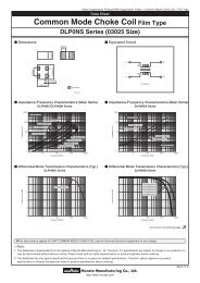
<strong>Technical</strong> Guide of Electrical Double Layer Capacitor1. The Structure and Principles of Electrical Double Layer Capacitor1-1. Principles of Electrical Double Layer Capacitor (EDLC)1-2. Structure of EDLC1-3. Equivalent circuit of EDLC1-4. Features of <strong>Murata</strong>’s EDLC2. Electrical Characteristics of EDLC - How to select EDLC-2-1. Capacitance and ESR of EDLC2-2. Charge and discharge characteristics[1] Charge current[2] Charge characteristics[3] Calculation of discharging time2-3. Factors to consider in selecting optimum specifications[1] Energy loss by ESR (internal resistance)[2] Effect of temperature[3] Degradation of capacitance and ESR caused by temperature and voltage change3. Cautions for use3-1. Voltage3-2. Self heating3-3. Mounting conditions3-4. Storage conditions1
1. The Structure and Principle of Electrical Double Layer Capacitor1-1. Principle of Electrical Double Layer CapacitorUnlike a ceramic capacitor or aluminum electrolytic capacitor, the ElectricalDouble Layer Capacitor (EDLC) contains no conventional dielectric. Instead, anelectrolyte (solid or liquid) is filled between two electrodes (see figure 1). InEDLC, an electrical condition called “electrical double layer”, which is formedbetween the electrodes and electrolyte, works as the dielectric.Capacitance is proportional to the surface area of the electrical double layer.Therefore using activated carbon, which has large surface area for electrodes,enables EDLC to have high capacitance.The mechanism of ion absorption and desorption to the electrical doublelayer contributes to charge and discharge of EDLCBy applying voltage to the facing electrodes, ions are drawn to the surface of theelectrical double layer and EDLC is charged. Conversely, they move away whendischarging EDLC. This is how EDLC is charged and discharged. (see figure 2) Electrical Double LayerIon absorptionIon desorption1-2. Structure of EDLCEDLC consists of electrodes, electrolyte (and electrolyte salt), and the separator, which prevents facingelectrodes from contacting each other. Activated carbon powder is applied to the electricity collector of theelectrodes. The electrical double layer is formed on the surface where each powder connects with an electrolyte(see figure 3)Figure 2: Charge and Discharge of EDLC2Considering this structure asa simple equivalent circuit,EDLC is shown by anode andcathode capacitors (C1, C2),separator, interelectroderesistance which consists ofresistance of separator andelectrolyte (Rs), electroderesistance which consists ofactivated carbon electrode andcollector (Re) ,and isolationresistance(R) (see figure4)
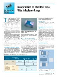
1-3. Equivalent circuit of EDLCActivated carbon electrodes consist of a various size of powder with holes on their respective surfaces. Theelectrical double layer is formed on the surface where each powder contacts with the electrolyte (see figure5)Therefore, equivalent circuit electrode resistance (Re) and resistance caused by ion moving (Rs) are shownby a complicated equivalent circuit where various resistances are connected to capacitors in series (seefigure6).Direction of + ion movementSeparatorSurfaceFigure 5: Electrode StructureEnlarged view ofactivated carbon1-4. Features of <strong>Murata</strong>’s EDLC<strong>Murata</strong>’s EDLC achieves low ESR and high capacitance in a small package based on the technologyintroduced by CAP-XX Ltd. The reduction of ESR was achieved by reducing electrode resistance (Re)by using electrode structure and optimum raw materials, and reducing the interelectrode resistance(Rs) of separator and electrolyte. High discharge efficiency because of low ESR High voltage Small and slim package Low ESR even at low temperature Long cycle life –exceeding 100k cyclesActivatedcarbonSeparatorAluminum foilPartition filmDMF / DMT Series3
2. Electrical characteristics of EDLC ~ How to select EDLC~2-1.Capacitance and ESR of EDLCBecause EDLC has high capacitance, it can be used as an energy supply device for back up or peakpower. Unlike a battery, the electric potential of EDLC becomes low by discharging EDLC. Therefore,energy stored in EDLC is shown by half of Q (charge) x V(voltage). However, EDLC consists ofcomplicated equivalent circuit as shown in figure 6. As such, actual measured capacitance value variesdepending on charge or discharge condition.<strong>Murata</strong>’s EDLC is a suitable product for using with relatively large current or high power, so wemeasure nominal capacitance at 100mA.Calculation of capacitanceTemperature: 25℃+/-5℃Discharge EDLC after charging by max voltagefor 30 minutes according to the profile and circuit(see figure 7).Charge/discharge current: 100mAV80%: 80% of Max voltageV40%: 40% of Max voltaget1: time to V80%t2: time to V40%Id: Discharge current (constant)Figure7ProfileCapacitance is calculated by the following formula (1).Nominal*capacitance(1):AC current meter:AC voltage meterC :Capacitor*Reference:V80%-V40% based on capacitance at 100mA dischargeCharge/discharge current 1A 100mA 10mA 1mA 0.1mACapacitance95% 100% 103% 107% 116%(Consider capacitance at100mA discharge as 100%)Measuring circuitNominal capacitanceCalculation of ESRESR is measured by AC method. It is calculated with the following formula (2) by measuringvoltage of both sides of the capacitor (Vc) applying 10mATemperature: 25℃+/-5℃Frequency: 1 kHzAC current (Ic): 10mACapacitor voltage: Vc(2):AC current meter:AC voltage meter:OscillatorC :Capacitor4
…2-2. Charge and discharge characteristics[1] Charge currentAs shown in figure 6, EDLC is an assembly of several capacitors which has various capacitances(C)and resistance (R) values. When EDLC’s CR value is small, it can be charged in a short time. On theother hand, when CR value is large, it needs a long charging time. Therefore, the sum of In isconsidered as leakage current (LC). The current value that flows through RLC (the actual leakageR1 C1current component) is too small to be measured.V -tIn = exp ( ) (3)I1R2 C2Rn CnRnI2R3C3VI3RnCnInR LCILC[2] Charge characteristics Constant voltage charge(Constant resistance charge)As noted in section 2-1, when charging EDLC at a low current, it takes longer time than the charging timecalculated according to the nominal capacitance. Charge voltage characteristic is shown by following formula (4).Constant voltage chargeV = Vc { 1Load current: IDischarging time: tn-th capacitor: Cnn-th resistor: Rnn-th load current: InLeakage current; ILCInsulation resistance: RLCCharge voltage: V-t- exp( ) }CRCharge voltage: VcNominal capacitance: CCharge resistance: R(4)5
[3] Calculation of discharging timeUnlike a secondary battery, the voltage of EDLC drops according to discharge current. The voltage alsodrops proportionately because of the internal resistance (ESR) of the capacitor. These voltage drops affectoutput, especially when EDLC is used with high discharge current and a decrease in voltage. Therefore, it isnecessary to calculate the needed characteristics (capacitance, ESR, series or parallel numbers ofcapacitors) considering the voltage drop. Calculation formulas are shown below. Discharging at constant current Discharging at constant powerDischarging time (t)Ct = (Vc-Vt)ILoad current (constant): IDischarging time: tDischarge voltage: VcCapacitor voltage: VtCapacitance: CDischarging time (t)1t = (CVc 2 -CVt 2 )2PPower (constant): PDischarging time: tDischarge voltage:VcCapacitor voltage: VtCapacitance: C(5)(6) Discharging at constant resistanceDischarging time (t)Vtt = - C x R x In ( )VcResistance (constant): RDischarging time: tDischarge voltage: VCCapacitor voltage: VtCapacitance: C(7)6
2-3. Factors to consider in selecting optimum spec[1]Energy loss by internal resistance (ESR)[2]Effect of temperature[3]Degradation of capacitance and ESRcaused by temperature and voltage change[1] Energy loss by ESR (internal resistance)When discharging EDLC at high current, large power, or low ESR, it is necessary to consider energy losscaused by capacitor resistance.Ct = (Vc - Vt - I x ESR) (8)IDischarging time: tLoad current: IDischarge voltage: VcCapacitor voltage: VtCapacitance: C1t = (CVc 2 -CVt 2 ) - ESR x I(t) 2 ・dt2P∫ t 0Discharging time: tPower: PDischarge voltage: VcCapacitor voltage: VtCapacitance: CBecause <strong>Murata</strong>’s EDLC has low ESR, energy loss caused by large current or large power is small anddischarge efficiency is high. However, when output power or current becomes larger, discharge efficiencybecomes low and in some cases EDLC cannot provide enough discharging time. When discharging time is notenough, please use several EDLC in series or in parallel.(9)Constant current discharge profile(@25℃)(e.g. DMF series 350mF)Constant power discharge profile(@25℃)(e.g. DMF series 350mF)Discharge efficiency from 2.7V to1.0V7
Discharge Efficiency from 5.5V to2.0VDischarge efficiency (constant current discharge)Discharge efficiency (constant power discharge)1A 2A 4A 8A 1W 5W 10W 20WDischargeCharge(C)Q 1.21 1.16 1.08 0.93energy(J) 4.58 4.22 3.82 3.11EDischargeefficiency (%)Q/Q 099 95 88 76Dischargeefficiency (%)E/E 0Standard charge (Q 0 ) calculationusing nominal capacitanceQ0=C (Vc-Vt) =0.35 x (5.5-2.0)=1.23(C) E0=2100 92 83 68Standard discharge energy (E 0 ) calculationusing nominal capacitance.1 x C(Vc 2 -Vt 2 ) = 0.5 x 0.35(5.5 2 -2.0 2 )=4.59(J)[2] Effect of temperatureESR of EDLC depends on temperature. When temperature becomes low,ESR becomes high. Therefore, when using EDLC at low temperature,discharge efficiency becomes low. Although <strong>Murata</strong>’s EDLC is designed toprovide stable output throughout a wide range of temperatures, consider energyloss by ESR increase if neededDischarge efficiency data(DMF rated voltage 5.5V, nominal capacitance 330mF, ESR60mΩ)Charge condition: 5.5V 30minDischarge efficiency from 5.5V to 2.0V is shown below in two patterns:Constant current discharge profile and constant power discharge profile.Discharge efficiency at low temperature is lower than at room temperatureESR change400%350%300%250%200%150%100%50%0%-50%-40 -30 -20 -10 0 10 20 30 40 50 60 70 80Temperature [℃ ]< Constant current discharge profile > < Constant power discharge profile >(e.g. DMF series 350mF)(e.g. DMF series 350mF) < Constant power discharge >1A 2A 4A 1W 5W 10WCharge(C) 25℃Discharge1.21 1.16 1.0825℃ 4.58 4.22 3.82energy(J)Q-30℃ 1.01 0.83 0.55 E -30℃ 3.78 2.20 1.56Discharge25℃Discharge99 95 88efficiency (%)efficiency (%)25℃ 100 92 83Q/Q 0 -30℃ 83 68 45 E/E 0 -30℃ 82 48 34Standard charge (Q 0) calculationStandard discharge energy(E 0 ) calculationusing nominal capacitanceusing nominal capacitanceQ 0 =C(Vc-Vt)=0.35 x(5.5-2.0)=1.23(C) E 0 = 1 x C(Vc 2 -Vt 2 ) = 0.5 x 0.35(5.5 2 -2.0 2 )=4.59(J)28
[3] Degradation of capacitance and ESRcaused by temperature and voltage changeGenerally speaking, when temperature drops 10 degrees, the life time of EDLC is doubled. EDLChas two degradation patterns. One is degradation of the electrochemical system (such as electrodeor electrolyte caused by applying voltage) and the other is drying up by the evaporation of electrolyte.In both cases, ESR increases and capacitance decreases. The final failure is open mode byincreasing internal resistance. In order to use EDLC reliably over the long term, close attention mustbe paid to the operating temperature condition.How much the voltage accelerates degradation is still not fully understood. It depends on voltagecondition and environment of usage. For details, please contact your local <strong>Murata</strong> representative.(Example)Degradation of capacitance and ESRLoad:DC4.2V@70℃Capacitance change0%-10%-20%-30%-40%-50%Capacitance0 100 200 300 400 500 600 700 800 900 1000Time (hr)ESR change100%90%80%70%60%50%40%30%20%10%0%ESR0 100 200 300 400 500 600 700 800 900 1000Time (hr)For example, according to above graph, the capacitance drops to 15% at 1000hrs. The time thecapacitance drops to 15% under the condition of 4.2V, 40℃ is calculated by the following formula:1,000hrs x 2 (70-40/10) =8,000hrs9
If you would like to provide the information requested for the conditionsbelow, <strong>Murata</strong> can make more detailed proposals based oncustomer-specific applications.Discharge condition of capacitorDischarge ConditionEDLC voltage1. Max charge voltageVMaxEarly voltage characteristic2. Allowable Min.voltageVminDischarging timeRequired charge (c)or Energy (J)Energy (J) =Power (W) x Discharging time t(sec)Charge (c) = Current (A) x Discharging time t(sec)ChargeconditionDischargeconditionUsageenvironmentCondition Example PurposeCharge voltage for 2.5V To confirm required number of cells incapacitorseries and consider discharge time.Charge voltage VmaxCharge current 500mA(in case of constantcurrent charge)Charge(C)orEnergy(J)Power × time(W x sec)orCurrent × time(A × sec)Numbers of discharge ona single chargeAccepted lower limit ofvoltage VminMinimum operationtemperatureActual usagetemperatureprofile150mJor300mC1.5W×100msecor3A×100msecNumbers of dischargeon a single charge( 5 times)1.3(V)To confirm required currentRegarding discharge effectiveness, itis necessary to consider max power orcurrent because it is affected by energyloss caused by internal resistanceTo calculate the discharging time.-20℃ At low temperature, dischargeeffectiveness decreases because ofESR increase.Under 40℃(typ)30000hrs70℃(Max)Under 500hrsOthers Loss on the circuit Effectiveness(%)orResistance(Ω)To confirm capacitance decrease andESR increase throughout the product lifeTo Confirm required capacitance。10
3. Cautions for use3-1. Voltage Resistance voltage of EDLCBy using an organic electrolyte, <strong>Murata</strong>’s EDLC provide high voltage. However, applying a highervoltage than rated voltage on EDLC may cause degradation. Please ensure not to apply excessivevoltage on EDLC.When using several EDLCs in series, voltage may become unbalanced and excessive voltage maybe applied. Therefore, consider applying enough voltage margin and balance control Series/Parallel useUse several capacitors in series according to required voltage. When discharging time needs to beincreased, please use several capacitors in parallel Voltage balanceWhen using capacitors in series, use balance resistance in parallel to the capacitor or use anactive balance circuit. For more details, see <strong>Murata</strong>’s specification sheetIf there are temperature gaps between capacitors, voltage will lose balance. Ensure that there is notemperature gap between capacitors. PolarityVerify the orientation of EDLC before use in accordance with the markings of polarity on theproducts. In principle, EDLC has no polarity. However, EDLC cannot be used under AC. Using EDLCunder AC condition may cause degradation and leakage3-2. Self HeatingPlease use EDLC under ensured temperature considering self heating of a capacitor. Please see ourspecification sheet for further details.3-3. Mounting condition<strong>Murata</strong>’s EDLC product is non reflowable due to the internal chemical system.For mounting, please use solder iron or special connector. Please see our specification sheet forrecommended soldering3-4. Storage conditionPlease avoid storage at high temperature or high humidity. Please see our catalog or specificationsheet for further details.11