Safety Standard Certified Ceramic Capacitors/High Voltage ... - Murata
Safety Standard Certified Ceramic Capacitors/High Voltage ... - Murata
Safety Standard Certified Ceramic Capacitors/High Voltage ... - Murata

You also want an ePaper? Increase the reach of your titles
YUMPU automatically turns print PDFs into web optimized ePapers that Google loves.
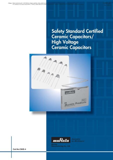
!Note • Please read rating and !CAUTION (for storage, operating, rating, soldering, mounting and handling) in this catalog to prevent smoking and/or burning, etc.• This catalog has only typical specifications. Therefore, please approve our product specifi cations or transact the approval sheet for product specifi cations before ordering.<strong>Safety</strong> <strong>Standard</strong> <strong>Certified</strong> <strong>Ceramic</strong> <strong>Capacitors</strong>C85E.pdfApr.7,20141Type KY (Basic Insulation) -Class X1, Y2- (Recommend)c Features1. Compact size; diameter 25% less than Type KH.2. Operating temperature range guaranteed up to 125degrees C.3. Dielectric strength:AC2000V (for lead spacing F=5mm)AC2600V (for lead spacing F=7.5mm)4. Class X1/Y2 capacitors certifi ed byUL/CSA/VDE/BSI/SEMKO/DEMKO/FIMKO/NEMKO/ESTI/NSW/CQC.5. Coated with fl ame-retardant epoxy resin(conforming to UL94V-0 standard).We recommend a halogen-free product* as ourstandard item.* Cl=900ppm max., Br=900ppm max. andCl+Br=1500ppm max.6. Taping available for automatic insertion.7. AC300V Rated <strong>Voltage</strong> item are newly added.c Applications1. Ideal for use as X/Y capacitors for AC line fi ltersand primary-secondary coupling on switching powersupplies and AC adapters.2. Ideal for use on D-A isolation and noise absorptionfor DAA modems without transformers.[Bulk]Vertical Crimp Long (A2, A3)[Bulk]Vertical Crimp Short (B2, B3)D max.eF±1.0T max.25.0 min.3.0 max.ød(in mm)Lead Code Coating Extension e ødA2, A3 Up to the end of crimp 0.6±0.05D max.eF±0.85.0±1.0T max.ød(in mm)Lead Code Coating Extension e ødB2, B3 Up to the end of crimp 0.6±0.053.0 max.Do not use these products in any automotivepower train or safety equipment including batterychargers for electric vehicles and plug-in hybrids.Only <strong>Murata</strong> products clearly stipulated as"for Automotive use" on its catalog can be usedfor automobile applications such as power train andsafety equipment.c <strong>Standard</strong> CertificationULCSAVDEBSISEMKODEMKOFIMKONEMKOESTINSW<strong>Standard</strong> No.UL60384-14CSA E60384-14IEC 60384-14EN 60384-14EN 60065 (8.8, 14.2)IEC 60384-14EN 60384-14IEC 60384-14EN 60384-14IEC 60384-14AS3250<strong>Certified</strong> No.E37921128328040006273KM 379011207848D0100224197P1221509412.01026824Rated <strong>Voltage</strong>250Vac (r.m.s.)CQC06001017446CQC GB/T14472CQC06001017447 ULCSAVDEBSISEMKODEMKOFIMKONEMKOESTINSW<strong>Standard</strong> No.UL60384-14CSA E60384-14IEC 60384-14EN 60384-14EN 60065 (8.8, 14.2)IEC 60384-14EN 60384-14IEC 60384-14EN 60384-14IEC 60384-14AS3250<strong>Certified</strong> No.E37921128328040006273KM 379011207848D0100224197P1221509412.01026824Rated <strong>Voltage</strong>300Vac (r.m.s.)CQC12001079706CQC IEC 60384-14CQC12001079940 5
!Note • Please read rating and !CAUTION (for storage, operating, rating, soldering, mounting and handling) in this catalog to prevent smoking and/or burning, etc.• This catalog has only typical specifications. Therefore, please approve our product specifi cations or transact the approval sheet for product specifi cations before ordering.C85E.pdfApr.7,20141c MarkingwqtExample472MKY250~X1Y2 HF0D 8erItemq Type Designation KYw Nominal Capacitance(Under 100pF: Actual value,100pF and over: 3 digit system)e Capacitance Tolerancer Company Name Code8 : Made in Taiwan 15 : Made in Thailandt Manufactured Date CodeClass CodeX1Y2Rated <strong>Voltage</strong> Mark 250~, 300~Halogen Free Mark HFRated <strong>Voltage</strong> 250Vaco Lead Spacing F=7.5mmPart NumberAC Rated<strong>Voltage</strong>Temp.Char.CapacitanceBodyDia. DLeadSpacing F(mm)BodyThickness TLeadPackageLong BulkLeadPackageShort BulkDE21XKY100JpppM02F 250Vac(r.m.s.) SL 10pF±5% 8.0mm max. 7.5 5.0mm max. A3B B3B N3ADE21XKY150JpppM02F 250Vac(r.m.s.) SL 15pF±5% 8.0mm max. 7.5 5.0mm max. A3B B3B N3ADE21XKY220JpppM02F 250Vac(r.m.s.) SL 22pF±5% 8.0mm max. 7.5 5.0mm max. A3B B3B N3ADE21XKY330JpppM02F 250Vac(r.m.s.) SL 33pF±5% 8.0mm max. 7.5 5.0mm max. A3B B3B N3ADE21XKY470JpppM02F 250Vac(r.m.s.) SL 47pF±5% 8.0mm max. 7.5 5.0mm max. A3B B3B N3ADE21XKY680JpppM02F 250Vac(r.m.s.) SL 68pF±5% 8.0mm max. 7.5 5.0mm max. A3B B3B N3ADE2B3KY101KpppM02F 250Vac(r.m.s.) B 100pF±10% 7.0mm max. 7.5 5.0mm max. A3B B3B N3ADE2B3KY151KpppM02F 250Vac(r.m.s.) B 150pF±10% 7.0mm max. 7.5 5.0mm max. A3B B3B N3ADE2B3KY221KpppM02F 250Vac(r.m.s.) B 220pF±10% 7.0mm max. 7.5 5.0mm max. A3B B3B N3ADE2B3KY331KpppM02F 250Vac(r.m.s.) B 330pF±10% 7.0mm max. 7.5 5.0mm max. A3B B3B N3ADE2B3KY471KpppM02F 250Vac(r.m.s.) B 470pF±10% 7.0mm max. 7.5 5.0mm max. A3B B3B N3ADE2B3KY681KpppM02F 250Vac(r.m.s.) B 680pF±10% 8.0mm max. 7.5 5.0mm max. A3B B3B N3ADE2E3KY102MpppM02F 250Vac(r.m.s.) E 1000pF±20% 7.0mm max. 7.5 5.0mm max. A3B B3B N3ADE2E3KY152MpppM02F 250Vac(r.m.s.) E 1500pF±20% 7.0mm max. 7.5 5.0mm max. A3B B3B N3ADE2E3KY222MpppM02F 250Vac(r.m.s.) E 2200pF±20% 8.0mm max. 7.5 5.0mm max. A3B B3B N3ADE2E3KY332MpppM02F 250Vac(r.m.s.) E 3300pF±20% 9.0mm max. 7.5 5.0mm max. A3B B3B N3ADE2E3KY472MpppM02F 250Vac(r.m.s.) E 4700pF±20% 10.0mm max. 7.5 5.0mm max. A3B B3B N3ADE2F3KY103MpppM02F 250Vac(r.m.s.) F 10000pF±20% 14.0mm max. 7.5 5.0mm max. A3B B3B N3AThree blank columns are fi lled with the lead and packaging codes. Please refer to the 3 columns on the right for the appropriate code.Individual specifi cation code "M02" expresses "simplicity marking and guarantee of dielectric strength between lead wires: AC2600V."<strong>Murata</strong> part numbers might be changed depending on lead code or any other changes. Therefore, please specify only the type name (KY) and capacitance of productsin the parts list when it is required for applying safety standard of electric equipment.LeadPackageTapingo Lead Spacing F=5mmPart NumberAC Rated<strong>Voltage</strong>Temp.Char.CapacitanceBodyDia. DLeadSpacing F(mm)BodyThickness TLeadPackageLong BulkLeadPackageShort BulkLeadPackageTapingDE21XKY100JpppM01F 250Vac(r.m.s.) SL 10pF±5% 8.0mm max. 5.0 5.0mm max. A2B B2B N2ADE21XKY150JpppM01F 250Vac(r.m.s.) SL 15pF±5% 8.0mm max. 5.0 5.0mm max. A2B B2B N2ADE21XKY220JpppM01F 250Vac(r.m.s.) SL 22pF±5% 8.0mm max. 5.0 5.0mm max. A2B B2B N2ADE21XKY330JpppM01F 250Vac(r.m.s.) SL 33pF±5% 8.0mm max. 5.0 5.0mm max. A2B B2B N2ADE21XKY470JpppM01F 250Vac(r.m.s.) SL 47pF±5% 8.0mm max. 5.0 5.0mm max. A2B B2B N2ADE21XKY680JpppM01F 250Vac(r.m.s.) SL 68pF±5% 8.0mm max. 5.0 5.0mm max. A2B B2B N2ADE2B3KY101KpppM01F 250Vac(r.m.s.) B 100pF±10% 7.0mm max. 5.0 5.0mm max. A2B B2B N2ADE2B3KY151KpppM01F 250Vac(r.m.s.) B 150pF±10% 7.0mm max. 5.0 5.0mm max. A2B B2B N2ADE2B3KY221KpppM01F 250Vac(r.m.s.) B 220pF±10% 7.0mm max. 5.0 5.0mm max. A2B B2B N2ADE2B3KY331KpppM01F 250Vac(r.m.s.) B 330pF±10% 7.0mm max. 5.0 5.0mm max. A2B B2B N2ADE2B3KY471KpppM01F 250Vac(r.m.s.) B 470pF±10% 7.0mm max. 5.0 5.0mm max. A2B B2B N2ADE2B3KY681KpppM01F 250Vac(r.m.s.) B 680pF±10% 8.0mm max. 5.0 5.0mm max. A2B B2B N2ADE2E3KY102MpppM01F 250Vac(r.m.s.) E 1000pF±20% 7.0mm max. 5.0 5.0mm max. A2B B2B N2A6Continued on the following page.
!Note • Please read rating and !CAUTION (for storage, operating, rating, soldering, mounting and handling) in this catalog to prevent smoking and/or burning, etc.• This catalog has only typical specifications. Therefore, please approve our product specifi cations or transact the approval sheet for product specifi cations before ordering.Continued from the preceding page.Part NumberAC Rated<strong>Voltage</strong>Temp.Char.CapacitanceBodyDia. DLeadSpacing F(mm)BodyThickness TLeadPackageLong BulkLeadPackageShort BulkDE2E3KY152MpppM01F 250Vac(r.m.s.) E 1500pF±20% 7.0mm max. 5.0 5.0mm max. A2B B2B N2ADE2E3KY222MpppM01F 250Vac(r.m.s.) E 2200pF±20% 8.0mm max. 5.0 5.0mm max. A2B B2B N2ADE2E3KY332MpppM01F 250Vac(r.m.s.) E 3300pF±20% 9.0mm max. 5.0 5.0mm max. A2B B2B N2ADE2E3KY472MpppM01F 250Vac(r.m.s.) E 4700pF±20% 10.0mm max. 5.0 5.0mm max. A2B B2B N2AThree blank columns are fi lled with the lead and packaging codes. Please refer to the 3 columns on the right for the appropriate code.Individual specifi cation code "M01" expresses "simplicity marking and guarantee of dielectric strength between lead wires: AC2000V."<strong>Murata</strong> part numbers might be changed depending on lead code or any other changes. Therefore, please specify only the type name (KY) and capacitance of productsin the parts list when it is required for applying safety standard of electric equipment.LeadPackageTapingC85E.pdfApr.7,20141Rated <strong>Voltage</strong> 300Vaco Lead Spacing F=7.5mmPart NumberAC Rated<strong>Voltage</strong>Temp.Char.CapacitanceBodyDia. DLeadSpacing F(mm)BodyThickness TLeadPackageLong BulkLeadPackageShort BulkLeadPackageTapingDE2B3KY101KpppU02F 300Vac(r.m.s.) B 100pF±10% 7.0mm max. 7.5 5.0mm max. A3B B3B N3ADE2B3KY151KpppU02F 300Vac(r.m.s.) B 150pF±10% 7.0mm max. 7.5 5.0mm max. A3B B3B N3ADE2B3KY221KpppU02F 300Vac(r.m.s.) B 220pF±10% 7.0mm max. 7.5 5.0mm max. A3B B3B N3ADE2B3KY331KpppU02F 300Vac(r.m.s.) B 330pF±10% 7.0mm max. 7.5 5.0mm max. A3B B3B N3ADE2B3KY471KpppU02F 300Vac(r.m.s.) B 470pF±10% 7.0mm max. 7.5 5.0mm max. A3B B3B N3ADE2B3KY681KpppU02F 300Vac(r.m.s.) B 680pF±10% 8.0mm max. 7.5 5.0mm max. A3B B3B N3ADE2E3KY102MpppU02F 300Vac(r.m.s.) E 1000pF±20% 7.0mm max. 7.5 5.0mm max. A3B B3B N3ADE2E3KY152MpppU02F 300Vac(r.m.s.) E 1500pF±20% 7.0mm max. 7.5 5.0mm max. A3B B3B N3ADE2E3KY222MpppU02F 300Vac(r.m.s.) E 2200pF±20% 8.0mm max. 7.5 5.0mm max. A3B B3B N3ADE2E3KY332MpppU02F 300Vac(r.m.s.) E 3300pF±20% 9.0mm max. 7.5 5.0mm max. A3B B3B N3ADE2E3KY472MpppU02F 300Vac(r.m.s.) E 4700pF±20% 10.0mm max. 7.5 5.0mm max. A3B B3B N3ADE2F3KY103MpppU02F 300Vac(r.m.s.) F 10000pF±20% 14.0mm max. 7.5 5.0mm max. A3B B3B N3AThree blank columns are fi lled with the lead and packaging codes. Please refer to the 3 columns on the right for the appropriate code.Individual specifi cation code "U02" expresses "simplicity marking and guarantee of dielectric strength between lead wires: AC2600V."<strong>Murata</strong> part numbers might be changed depending on lead code or any other changes. Therefore, please specify only the type name (KY) and capacitance of productsin the parts list when it is required for applying safety standard of electric equipment.7
!Note • Please read rating and !CAUTION (for storage, operating, rating, soldering, mounting and handling) in this catalog to prevent smoking and/or burning, etc.• This catalog has only typical specifications. Therefore, please approve our product specifi cations or transact the approval sheet for product specifi cations before ordering.C85E.pdfApr.7,2014<strong>Safety</strong> <strong>Standard</strong> <strong>Certified</strong> <strong>Ceramic</strong> <strong>Capacitors</strong>2Type KH (Basic Insulation) -Class X1, Y2-c Features1. Operating temperature range guaranteed up to 125degrees C.2. Dielectric strength: AC2600V3. Class X1/Y2 capacitors certifi ed byUL/CSA/VDE/BSI/SEMKO/DEMKO/FIMKO/NEMKO/ESTI/NSW.4. Coated with fl ame-retardant epoxy resin (conformingto UL94V-0 standard).Please contact us when a halogen-free product*is necessary.* Cl=900ppm max., Br=900ppm max. andCl+Br=1500ppm max.5. Taping available for automatic insertion.[Bulk]Vertical Crimp Long (A3)D max.eF±1.0T max.25.0 min.3.0 max.ød(in mm)Lead Code Coating Extension e ødA3 Up to the end of crimp 0.6±0.05D max.T max.c ApplicationsIdeal for use as X/Y capacitors for AC line fi lters andprimary-secondary coupling on switching power suppliesand AC adapters.eF±0.85.0±1.0ød3.0 max.Do not use these products in any automotivepower train or safety equipment including batterychargers for electric vehicles and plug-in hybrids.Only <strong>Murata</strong> products clearly stipulated as"for Automotive use" on its catalog can be usedfor automobile applications such as power train andsafety equipment.[Bulk]Vertical Crimp Short (B3)Lead CodeB3Coating Extension eUp to the end of crimp(in mm)ød0.6±0.05c <strong>Standard</strong> CertificationULCSAVDEBSISEMKODEMKOFIMKONEMKOESTINSW<strong>Standard</strong> No.UL60384-14CSA E60384-14IEC 60384-14EN 60384-14EN 60065 (8.8, 14.2)IEC 60384-14EN 60384-14IEC 60384-14EN 60384-14IEC 60384-14AS3250<strong>Certified</strong> No.E37921134380540002796KM 379011200285D0100624195P1221509512.01046529Rated <strong>Voltage</strong>250Vac (r.m.s.) c MarkingqwKH472MX1Y2BSIMJ502Example250~FIND865ertItemq Type DesignationKHw Nominal Capacitance(Marked with 3 figures)e Capacitance Tolerancer Company Name Code8 : Made in Taiwan 15 : Made in Thailandt Manufactured Date CodeUL Approval MarkCSA Approval MarkVDE Approval MarkBSI Approval MarkBSISEMKO Approval MarkDEMKO Approval Mark DFIMKO Approval MarkFINEMKO Approval Mark NESTI Approval MarkMJ502Class CodeX1Y2Rated <strong>Voltage</strong> Mark250~8
!Note • Please read rating and !CAUTION (for storage, operating, rating, soldering, mounting and handling) in this catalog to prevent smoking and/or burning, etc.• This catalog has only typical specifications. Therefore, please approve our product specifi cations or transact the approval sheet for product specifi cations before ordering.C85E.pdfApr.7,2014Part NumberAC Rated<strong>Voltage</strong>Temp.Char.CapacitanceBodyDia. DLeadSpacing F(mm)BodyThickness TLeadPackageLong BulkLeadPackageShort BulkDE2B3KH101Kppp 250Vac(r.m.s.) B 100pF±10% 8.0mm max. 7.5 7.0mm max. A3B B3B N3ADE2B3KH151Kppp 250Vac(r.m.s.) B 150pF±10% 8.0mm max. 7.5 7.0mm max. A3B B3B N3ADE2B3KH221Kppp 250Vac(r.m.s.) B 220pF±10% 8.0mm max. 7.5 7.0mm max. A3B B3B N3ADE2B3KH331Kppp 250Vac(r.m.s.) B 330pF±10% 8.0mm max. 7.5 7.0mm max. A3B B3B N3ADE2B3KH471Kppp 250Vac(r.m.s.) B 470pF±10% 8.0mm max. 7.5 7.0mm max. A3B B3B N3ADE2B3KH681Kppp 250Vac(r.m.s.) B 680pF±10% 9.0mm max. 7.5 7.0mm max. A3B B3B N3ADE2E3KH102Mppp 250Vac(r.m.s.) E 1000pF±20% 8.0mm max. 7.5 7.0mm max. A3B B3B N3ADE2E3KH152Mppp 250Vac(r.m.s.) E 1500pF±20% 9.0mm max. 7.5 7.0mm max. A3B B3B N3ADE2E3KH222Mppp 250Vac(r.m.s.) E 2200pF±20% 10.0mm max. 7.5 7.0mm max. A3B B3B N3ADE2E3KH332Mppp 250Vac(r.m.s.) E 3300pF±20% 12.0mm max. 7.5 7.0mm max. A3B B3B N3ADE2E3KH472Mppp 250Vac(r.m.s.) E 4700pF±20% 13.0mm max. 7.5 7.0mm max. A3B B3B N3ADE2F3KH103Mppp 250Vac(r.m.s.) F 10000pF±20% 16.0mm max. 7.5 7.0mm max. A3B B3B N7AThree blank columns are fi lled with the lead and packaging codes. Please refer to the 3 columns on the right for the appropriate code.<strong>Murata</strong> part numbers might be changed depending on lead code or any other changes. Therefore, please specify only the type name (KH) and capacitance of productsin the parts list when it is required for applying safety standard of electric equipment.LeadPackageTaping29
!Note • Please read rating and !CAUTION (for storage, operating, rating, soldering, mounting and handling) in this catalog to prevent smoking and/or burning, etc.• This catalog has only typical specifications. Therefore, please approve our product specifi cations or transact the approval sheet for product specifi cations before ordering.C85E.pdfApr.7,2014<strong>Safety</strong> <strong>Standard</strong> <strong>Certified</strong> <strong>Ceramic</strong> <strong>Capacitors</strong>Type KX New Small Size (Reinforced Insulation) -Class X1, Y1- (Recommend)3c Features1. We design capacitors much more compact in size thancurrent Type KX, having reduced the diameterby 20% max.2. Operating temperature range guaranteed up to 125degrees C.3. Dielectric strength: AC4000V4. Class X1/Y1 capacitors certifi ed byUL/CSA/VDE/BSI/SEMKO/DEMKO/FIMKO/NEMKO/ESTI/IMQ/CQC.5. Can be use with a component in appliancesrequiring reinforced insulation and doubleinsulation based on UL1492, IEC60065 and IEC60950.6. Coated with fl ame-retardant epoxy resin (conformingto UL94V-0 standard).We recommend a halogen-free product* as ourstandard item.* Cl=900ppm max., Br=900ppm max. andCl+Br=1500ppm max.7. Taping available for automatic insertion.8. AC300V Rated <strong>Voltage</strong> item are newly added.c Applications1. Ideal for use as X/Y capacitors for AC line fi ltersand primary-secondary coupling on switching powersupplies and AC adapters.2. Ideal for use on D-A isolation and noise absorptionfor DAA modems without transformers.[Bulk]Vertical Crimp Long (A4)[Bulk]Vertical Crimp Short (B4)D max.eF±1.0T max.25.0 min.3.0 max.ød(in mm)Lead Code Coating Extension e ødA4 Up to the end of crimp 0.6±0.05D max.eF±0.85.0±1.0T max.ød(in mm)Lead Code Coating Extension e ødB4 Up to the end of crimp 0.6±0.053.0 max.Do not use these products in any automotivepower train or safety equipment including batterychargers for electric vehicles and plug-in hybrids.Only <strong>Murata</strong> products clearly stipulated as"for Automotive use" on its catalog can be usedfor automobile applications such as power train andsafety equipment.*: Small sized Type KX differs from current Type KXin electrical characteristics, such as the voltagedependency, capacitance temperature dependency,and Dielectric strength.Therefore, before replacing current Type KX,please make a performance check by equipment.Please also refer to Notice (Rating) item 2,"Performance Check by Equipment," below.10
!Note • Please read rating and !CAUTION (for storage, operating, rating, soldering, mounting and handling) in this catalog to prevent smoking and/or burning, etc.• This catalog has only typical specifications. Therefore, please approve our product specifi cations or transact the approval sheet for product specifi cations before ordering.C85E.pdfApr.7,2014c <strong>Standard</strong> Certification Rated <strong>Voltage</strong> (AC250V) B, E Char.ULCSAVDEBSISEMKODEMKOFIMKONEMKOESTIIMQCQC<strong>Standard</strong> No.UL60384-14CSA E60384-14IEC 60384-14EN 60384-14EN 60065 (8.8, 14.2)IEC 60384-14EN 60384-14IEC 60384-14EN 60384-14EN 60384-14GB/T14472<strong>Certified</strong> No.E37921134381040002831KM 379011200074D0100424191P1221509612.0094V4069CQC02001001556CQC04001011643 c Marking Rated <strong>Voltage</strong> (AC250V) B, E Char.wqtExample472MKX250~X1Y1 HF0D 8Itemq Type Designation KXw Nominal Capacitance (3 digit system)e e Capacitance Tolerancer Company Name Code8 : Made in Taiwan 15 : Made in Thailandr t Manufactured Date CodeClass CodeX1Y1Rated <strong>Voltage</strong> Mark 250~Halogen Free Mark HF3c <strong>Standard</strong> Certification Rated <strong>Voltage</strong> (AC300V) B, E Char.ULCSAVDEBSISEMKODEMKOFIMKONEMKOESTIIMQCQC<strong>Standard</strong> No.UL60384-14CSA E60384-14IEC 60384-14EN 60384-14EN 60065 (8.8, 14.2)IEC 60384-14EN 60384-14IEC 60384-14EN 60384-14EN 60384-14IEC 60384-14<strong>Certified</strong> No.E37921134381040002831KM 379011200074D0100424191P1221509612.0094V4069CQC12001079735CQC12001079941 c Marking Rated <strong>Voltage</strong> (AC300V) B, E Char.wqtExample472MKX300~X1Y1 HF0D 8Itemq Type Designation KXw Nominal Capacitance (3 digit system)e e Capacitance Tolerancer Company Name Code8 : Made in Taiwan 15 : Made in Thailandr t Manufactured Date CodeClass CodeX1Y1Rated <strong>Voltage</strong> Mark 300~Halogen Free Mark HFRated <strong>Voltage</strong> 250VacPart NumberAC Rated<strong>Voltage</strong>Temp.Char.CapacitanceBodyDia. DLeadSpacing F(mm)BodyThickness TLeadPackageLong BulkLeadPackageShort BulkDE1B3KX101KpppN01F 250Vac(r.m.s.) B 100pF±10% 7.0mm max. 10.0 7.0mm max. A4B B4B N4ADE1B3KX151KpppN01F 250Vac(r.m.s.) B 150pF±10% 7.0mm max. 10.0 7.0mm max. A4B B4B N4ADE1B3KX221KpppN01F 250Vac(r.m.s.) B 220pF±10% 8.0mm max. 10.0 7.0mm max. A4B B4B N4ADE1B3KX331KpppN01F 250Vac(r.m.s.) B 330pF±10% 7.0mm max. 10.0 7.0mm max. A4B B4B N4ADE1B3KX471KpppN01F 250Vac(r.m.s.) B 470pF±10% 7.0mm max. 10.0 7.0mm max. A4B B4B N4ADE1B3KX681KpppN01F 250Vac(r.m.s.) B 680pF±10% 8.0mm max. 10.0 7.0mm max. A4B B4B N4ADE1E3KX102MpppN01F 250Vac(r.m.s.) E 1000pF±20% 7.0mm max. 10.0 7.0mm max. A4B B4B N4ADE1E3KX152MpppN01F 250Vac(r.m.s.) E 1500pF±20% 8.0mm max. 10.0 7.0mm max. A4B B4B N4ADE1E3KX222MpppN01F 250Vac(r.m.s.) E 2200pF±20% 9.0mm max. 10.0 7.0mm max. A4B B4B N4ADE1E3KX332MpppN01F 250Vac(r.m.s.) E 3300pF±20% 10.0mm max. 10.0 7.0mm max. A4B B4B N4ADE1E3KX472MpppN01F 250Vac(r.m.s.) E 4700pF±20% 12.0mm max. 10.0 7.0mm max. A4B B4B N4AThree blank columns are fi lled with the lead and packaging codes. Please refer to the 3 columns on the right for the appropriate code.<strong>Murata</strong> part numbers might be changed depending on lead code or any other changes. Therefore, please specify only the type name (KX) and capacitance of productsin the parts list when it is required for applying safety standard of electric equipment.Please contact us when less than 100pF capacitance product is necessary.LeadPackageTaping11
!Note • Please read rating and !CAUTION (for storage, operating, rating, soldering, mounting and handling) in this catalog to prevent smoking and/or burning, etc.• This catalog has only typical specifications. Therefore, please approve our product specifi cations or transact the approval sheet for product specifi cations before ordering.C85E.pdfApr.7,2014Rated <strong>Voltage</strong> 300Vac3Part NumberAC Rated<strong>Voltage</strong>Temp.Char.CapacitanceBodyDia. DLeadSpacing F(mm)BodyThickness TLeadPackageLong BulkLeadPackageShort BulkDE1B3KX101KpppP01F 300Vac(r.m.s.) B 100pF±10% 7.0mm max. 10.0 7.0mm max. A4B B4B N4ADE1B3KX151KpppP01F 300Vac(r.m.s.) B 150pF±10% 7.0mm max. 10.0 7.0mm max. A4B B4B N4ADE1B3KX221KpppP01F 300Vac(r.m.s.) B 220pF±10% 8.0mm max. 10.0 7.0mm max. A4B B4B N4ADE1B3KX331KpppP01F 300Vac(r.m.s.) B 330pF±10% 7.0mm max. 10.0 7.0mm max. A4B B4B N4ADE1B3KX471KpppP01F 300Vac(r.m.s.) B 470pF±10% 7.0mm max. 10.0 7.0mm max. A4B B4B N4ADE1B3KX681KpppP01F 300Vac(r.m.s.) B 680pF±10% 8.0mm max. 10.0 7.0mm max. A4B B4B N4ADE1E3KX102MpppP01F 300Vac(r.m.s.) E 1000pF±20% 7.0mm max. 10.0 7.0mm max. A4B B4B N4ADE1E3KX152MpppP01F 300Vac(r.m.s.) E 1500pF±20% 8.0mm max. 10.0 7.0mm max. A4B B4B N4ADE1E3KX222MpppP01F 300Vac(r.m.s.) E 2200pF±20% 9.0mm max. 10.0 7.0mm max. A4B B4B N4ADE1E3KX332MpppP01F 300Vac(r.m.s.) E 3300pF±20% 10.0mm max. 10.0 7.0mm max. A4B B4B N4ADE1E3KX472MpppP01F 300Vac(r.m.s.) E 4700pF±20% 12.0mm max. 10.0 7.0mm max. A4B B4B N4AThree blank columns are fi lled with the lead and packaging codes. Please refer to the 3 columns on the right for the appropriate code.<strong>Murata</strong> part numbers might be changed depending on lead code or any other changes. Therefore, please specify only the type name (KX) and capacitance of productsin the parts list when it is required for applying safety standard of electric equipment.LeadPackageTaping12
!Note • Please read rating and !CAUTION (for storage, operating, rating, soldering, mounting and handling) in this catalog to prevent smoking and/or burning, etc.• This catalog has only typical specifications. Therefore, please approve our product specifi cations or transact the approval sheet for product specifi cations before ordering.C85E.pdfApr.7,2014<strong>Safety</strong> <strong>Standard</strong> <strong>Certified</strong> <strong>Ceramic</strong> <strong>Capacitors</strong>Type KX (Reinforced Insulation) -Class X1, Y1-c Features1. Operating temperature range guaranteed up to 125degrees C.2. Dielectric strength: AC4000V3. Class X1/Y1 capacitors certifi ed byUL/CSA/VDE/BSI/SEMKO/DEMKO/FIMKO/NEMKO/ESTI/IMQ.4. Can be use with a component in appliancesrequiring reinforced insulation and doubleinsulation based on UL1492, IEC60065 and IEC60950.5. Coated with fl ame-retardant epoxy resin (conformingto UL94V-0 standard).Please contact us when a halogen-free product*is necessary.* Cl=900ppm max., Br=900ppm max. andCl+Br=1500ppm max.6. Taping available for automatic insertion.c ApplicationsIdeal for use as X/Y capacitors for AC line fi lters andprimary-secondary coupling on switching power suppliesand AC adapters.Do not use these products in any automotivepower train or safety equipment including batterychargers for electric vehicles and plug-in hybrids.Only <strong>Murata</strong> products clearly stipulated as"for Automotive use" on its catalog can be usedfor automobile applications such as power train andsafety equipment.[Bulk]Vertical Crimp Long (A5)[Bulk]Vertical Crimp Short (B5)eF±1.0Lead CodeA5eF±0.8Lead CodeB5D max.D max.25.0 min.T max.ødCoating Extension eUp to the end of crimp5.0±1.0T max.Coating Extension eødUp to the end of crimp4.0 max.4.0 max.(in mm)ød0.6± 0.10.05(in mm)ød0.6± 0.10.054c <strong>Standard</strong> CertificationULCSAVDEBSISEMKODEMKOFIMKONEMKOESTIIMQ<strong>Standard</strong> No.UL60384-14CSA E60384-14IEC 60384-14EN 60384-14EN 60065 (8.8, 14.2)IEC 60384-14EN 60384-14IEC 60384-14EN 60384-14EN 60384-14<strong>Certified</strong> No.E37921134381040002831KM 379011200074D0100424191P1221509612.0094V4069Rated <strong>Voltage</strong>250Vac (r.m.s.) c MarkingqExamplewKX222MX1Y1BSIFIMJ502N250~ D865ertItemq Type DesignationKXw Nominal Capacitance(Under 100pF: Actual value, 100pF and over: Marked with 3 figures)e Capacitance Tolerancer Company Name Code8 : Made in Taiwan 15 : Made in Thailandt Manufactured Date CodeUL Approval MarkCSA Approval MarkVDE Approval MarkBSI Approval MarkSEMKO Approval MarkDEMKO Approval MarkFIMKO Approval MarkNEMKO Approval MarkESTI Approval MarkIMQ Approval MarkClass CodeRated <strong>Voltage</strong> MarkBSIDFINMJ502X1Y1250~13
!Note • Please read rating and !CAUTION (for storage, operating, rating, soldering, mounting and handling) in this catalog to prevent smoking and/or burning, etc.• This catalog has only typical specifications. Therefore, please approve our product specifi cations or transact the approval sheet for product specifi cations before ordering.C85E.pdfApr.7,20144Part NumberAC Rated<strong>Voltage</strong>Temp.Char.CapacitanceBodyDia. DLeadSpacing F(mm)BodyThickness TLeadPackageLong BulkLeadPackageShort BulkDE1B3KX101Kppp 250Vac(r.m.s.) B 100pF±10% 9.0mm max. 10.0 8.0mm max. A5B B5B N5ADE1B3KX151Kppp 250Vac(r.m.s.) B 150pF±10% 9.0mm max. 10.0 8.0mm max. A5B B5B N5ADE1B3KX221Kppp 250Vac(r.m.s.) B 220pF±10% 9.0mm max. 10.0 8.0mm max. A5B B5B N5ADE1B3KX331Kppp 250Vac(r.m.s.) B 330pF±10% 9.0mm max. 10.0 8.0mm max. A5B B5B N5ADE1B3KX471Kppp 250Vac(r.m.s.) B 470pF±10% 9.0mm max. 10.0 8.0mm max. A5B B5B N5ADE1B3KX681Kppp 250Vac(r.m.s.) B 680pF±10% 10.0mm max. 10.0 8.0mm max. A5B B5B N5ADE1E3KX102MpppA01 250Vac(r.m.s.) E 1000pF±20% 8.0mm max. 10.0 8.0mm max. A5B B5B N5ADE1E3KX152MpppA01 250Vac(r.m.s.) E 1500pF±20% 9.0mm max. 10.0 8.0mm max. A5B B5B N5ADE1E3KX222MpppA01 250Vac(r.m.s.) E 2200pF±20% 10.0mm max. 10.0 8.0mm max. A5B B5B N5ADE1E3KX332MpppA01 250Vac(r.m.s.) E 3300pF±20% 12.0mm max. 10.0 8.0mm max. A5B B5B N5ADE1E3KX392MpppA01 250Vac(r.m.s.) E 3900pF±20% 13.0mm max. 10.0 8.0mm max. A5B B5B N5ADE1E3KX472MpppA01 250Vac(r.m.s.) E 4700pF±20% 15.0mm max. 10.0 8.0mm max. A5B B5B N5AThree blank columns are fi lled with the lead and packaging codes. Please refer to the 3 columns on the right for the appropriate code.<strong>Murata</strong> part numbers might be changed depending on lead code or any other changes. Therefore, please specify only the type name (KX) and capacitance of productsin the parts list when it is required for applying safety standard of electric equipment.LeadPackageTaping14
!Note • Please read rating and !CAUTION (for storage, operating, rating, soldering, mounting and handling) in this catalog to prevent smoking and/or burning, etc.• This catalog has only typical specifications. Therefore, please approve our product specifi cations or transact the approval sheet for product specifi cations before ordering.C85E.pdfApr.7,2014Type KY/KH/KX Specifications and Test MethodsOperating Temperature Range: -40 to +125°C (Except for UL/VDE, -25 to +125°C)No.Item1 Appearance and Dimensions2 Marking To be easily legible3 Capacitance Within specified toleranceSpecificationsNo visible defect, and dimensions are withinspecified range.Test MethodThe capacitor should be visually inspected for evidence ofdefect.Dimensions should be measured with slide calipers.The capacitor should be visually inspected.4Dissipation Factor (D.F.)QChar.B, EFSLSpecificationsD.F.V2.5%D.F.V5.0%QU400+20C* 1 (CF30pF)QU1000 (CU30pF)The capacitance, dissipation factor and Q should be measuredat 20˚C with 1±0.1kHz (char. SL: 1±0.1MHz) and AC5V(r.m.s.)max.5 Insulation Resistance (I.R.) 10000MΩ min.The insulation resistance should be measured withDC500±50V within 60±5 sec. of charging.The voltage should be applied to the capacitor through aresistor of 1MΩ.The capacitor should not be damaged when the test voltagesfrom Table 1 are applied between the lead wires for 60 sec.Between LeadWiresNo failureTypeKYKHKXTest <strong>Voltage</strong>For lead spacing F=5mm AC2000V(r.m.s.)For lead spacing F=7.5mm AC2600V(r.m.s.)AC2600V(r.m.s.)AC4000V(r.m.s.)6DielectricStrengthBodyInsulationNo failureFirst, the terminals of the capacitorshould be connected together. Then,as shown in the figure at right, a metalfoil should be closely wrapped aroundthe body of the capacitor to thedistance of about 3 to 6mm fromeach terminal.Then, the capacitor should be insertedinto a container filled with metal ballsof about 1mm diameter. Finally, ACvoltage from Table 2 is applied for 60 sec. between thecapacitor lead wires and metal balls.TypeKYKHKXTest <strong>Voltage</strong>AC2600V(r.m.s.)AC2600V(r.m.s.)AC4000V(r.m.s.)MetalFoilabout3 to 6mmMetalBallsChar. Capacitance ChangeBEWithin ±10%Within +20–55%7 Temperature CharacteristicsFWithin +30–80%(Temp. range: -25 to +85°C)8 Solderability of Leads* 1 "C" expresses nominal capacitance value (pF).Char. Temperature CoefficientSL +350 to -1000ppm/°C(Temp. range: +20 to +85°C)Lead wire should be soldered with uniform coatingon the axial direction over 3/4 of the circumferentialdirection.The capacitance measurement should be made at each stepspecified in Table 3.Step12345Temperature (ºC)20±2-25±220±285±220±2The lead wire of a capacitor should be dipped into moltensolder for 2±0.5 sec.The depth of immersion is up to about 1.5 to 2.0mm from theroot of lead wires.Temp. of solder: Lead Free Solder (Sn-3Ag-0.5Cu) 245±5°CH63 Eutectic Solder 235±5°CContinued on the following page.15
!Note • Please read rating and !CAUTION (for storage, operating, rating, soldering, mounting and handling) in this catalog to prevent smoking and/or burning, etc.• This catalog has only typical specifications. Therefore, please approve our product specifi cations or transact the approval sheet for product specifi cations before ordering.C85E.pdfApr.7,2014Type KY/KH/KX Specifications and Test MethodsContinued from the preceding page.No.910SolderingEffect(On-Preheat)ItemAppearanceCapacitanceChangeSoldering I.R.Effect(Non-Preheat)DielectricStrengthAppearanceCapacitanceChangeI.R.DielectricStrengthAppearanceSpecificationsNo marked defectWithin ±10%1000MΩ min.Per Item 6No marked defectWithin ±10%1000MΩ min.Per Item 6No marked defectTest MethodAs shown in the figure, the leadwires should be immersed in ThermalScreensolder of 350±10°C or 260±5°C upto 1.5 to 2.0mm from the root ofterminal for 3.5±0.5 sec. (10±1sec. for 260±5°C).Pre-treatment:Capacitor should be stored at 85±2°C for 1 hr., then placed atroom condition* 2 for 24±2 hrs. before initial measurements.Post-treatment:Capacitor should be stored for 1 to 2 hrs. at room condition.* 2First the capacitor should bestored at 120+0/-5°C for60+0/-5 sec.Then, as in the figure, the leadwires should be immersed insolder of 260+0/-5°C up to 1.5 to2.0mm from the root of terminalfor 7.5+0/-1 sec.Pre-treatment:ThermalScreenCapacitor1.5to 2.0mmMoltenSolderCapacitor1.5to 2.0mmMoltenSolderCapacitor should be stored at 85±2°C for 1 hr., then placed atroom condition* 2 for 24±2 hrs. before initial measurements.Post-treatment:Capacitor should be stored for 1 to 2 hrs. at room condition.* 211 VibrationResistanceCapacitanceD.F.QWithin the specified toleranceChar.B, EFSLSpecificationsD.F.V2.5%D.F.V5.0%QU400+20C* 1 (CF30pF)QU1000 (CU30pF)The capacitor should be firmly soldered to the supporting leadwire and vibrated at a frequency range of 10 to 55Hz, 1.5mm intotal amplitude, with about a 1-minute rate of vibration changefrom 10Hz to 55Hz and back to 10Hz.Apply for a total of 6 hrs., 2 hrs. each in 3 mutuallyperpendicular directions.AppearanceNo marked defectCapacitanceChangeChar.BE, FSLCapacitance ChangeWithin ±10%Within ±15%Within ± 5%12Humidity(UnderSteadyState)D.F.QChar.B, EFSLSpecificationsD.F.V5.0%D.F.V7.5%QU275+5/2C* 1 (CF30pF)QU350 (CU30pF)Set the capacitor for 500±12 hrs. at 40±2°C in 90 to 95%relative humidity.Post-treatment:Capacitor should be stored for 1 to 2 hrs. at room condition.* 2I.R.DielectricStrengthAppearance3000MΩ min.Per Item 6No marked defectCapacitanceChangeChar.BE, FSLCapacitance ChangeWithin ±10%Within ±15%Within ± 5%13 HumidityLoadingD.F.QChar.B, EFSLSpecificationsD.F.V5.0%D.F.V7.5%QU275+5/2C* 1 (CF30pF)QU350 (CU30pF)Apply the rated voltage for 500±12 hrs. at 40±2°C in 90 to 95%relative humidity.Post-treatment:Capacitor should be stored for 1 to 2 hrs. at room condition.* 2I.R.DielectricStrength3000MΩ min.Per Item 6* 1 "C" expresses nominal capacitance value (pF).* 2 "Room condition" Temperature: 15 to 35°C, Relative humidity: 45 to 75%, Atmospheric pressure: 86 to 106kPaContinued on the following page.16
!Note • Please read rating and !CAUTION (for storage, operating, rating, soldering, mounting and handling) in this catalog to prevent smoking and/or burning, etc.• This catalog has only typical specifications. Therefore, please approve our product specifi cations or transact the approval sheet for product specifi cations before ordering.C85E.pdfApr.7,2014Type KY/KH/KX Specifications and Test MethodsContinued from the preceding page.No.ItemSpecificationsTest MethodAppearanceCapacitanceChangeI.R.No marked defectWithin ±20%3000MΩ min.Impulse <strong>Voltage</strong>Each individual capacitor should be subjected to a 5kV (TypeKX: 8kV) impulses for three times. Then the capacitors areapplied to life test.100 (%)9050Front time (T1) =1.2μs=1.67TTime to half-value (T2) =50μs300Tt14 LifeDielectricStrengthPer Item 6T1T2Apply a voltage from Table 4 for 1000 hrs. at 125+2/-0°C, andrelative humidity of 50% max.Applied <strong>Voltage</strong>170% of Rated <strong>Voltage</strong> except that once each hour thevoltage is increased to AC1000V(r.m.s.) for 0.1 sec.Post-treatment:Capacitor should be stored for 1 to 2 hrs. at room condition.* 215RobustnessofTerminationsTensileBendingLead wire should not be cut off. Capacitor shouldnot be broken.As shown in the figure at right, fix the bodyof the capacitor and apply a tensile weightgradually to each lead wire in the radialdirection of the capacitor up to 10N and keepit for 10±1 sec.Each lead wire should be subjected to 5N of weight and bent90° at the point of egress, in one direction, then returned to itsoriginal position and bent 90° in the opposite direction at therate of one bend in 2 to 3 sec.WThe capacitor should be individually wrapped in at least one butnot more than two complete layers of cheesecloth. Thecapacitor should be subjected to 20 discharges. The intervalbetween successive discharges should be 5 sec. The UACshould be maintained for 2 min. after the last discharge.S1FL1L2RTrS2C1UACL3C2C3L4CxCtUt16 Active Flammability The cheesecloth should not be on fire.OscilloscopeC1,2 : 1μF±10% C3 : 0.033μF±5% 10kVL1 to 4 : 1.5mH±20% 16A Rod core chokeCt : 3μF±5% 10kV R : 100Ω±2%Cx : Capacitor under test UAC : UR±5%F : Fuse, Rated 10A UR : Rated <strong>Voltage</strong>Ut : <strong>Voltage</strong> applied to CtUx5kVtime* 2 "Room condition" Temperature: 15 to 35°C, Relative humidity: 45 to 75%, Atmospheric pressure: 86 to 106kPaContinued on the following page.17
!Note • Please read rating and !CAUTION (for storage, operating, rating, soldering, mounting and handling) in this catalog to prevent smoking and/or burning, etc.• This catalog has only typical specifications. Therefore, please approve our product specifi cations or transact the approval sheet for product specifi cations before ordering.C85E.pdfApr.7,2014Type KY/KH/KX Specifications and Test MethodsContinued from the preceding page.No.Item17 Passive FlammabilitySpecificationsThe burning time should not exceed 30 sec.The tissue paper should not ignite.The capacitor under test should be held in the flame in theposition that best promotes burning. Each specimen shouldonly be exposed once to the flame. Time of exposure to flame:30 sec.Length of flame : 12±1mmGas burner : Length 35mm min.Inside Dia. 0.5±0.1mmOutside Dia. 0.9mm max.Gas: Butane gas Purity 95% min.About 8mm45°Test Method200T5mmTest SpecimenTissueAbout 10mm Thick Board18TemperatureandImmersionCycleAppearanceCapacitanceChangeD.F.QI.R.DielectricStrengthNo marked defectChar.BE, FSLChar.B, EFSL3000MΩ min.Per Item 6Capacitance ChangeWithin ±10%Within ±20%Within ± 5%SpecificationsD.F.V5.0%D.F.V7.5%QU275+5/2C* 1 (CF30pF)QU350 (CU30pF)Step1234* 1 "C" expresses nominal capacitance value (pF).* 2 "Room condition" Temperature: 15 to 35°C, Relative humidity: 45 to 75%, Atmospheric pressure: 86 to 106kPaThe capacitor should be subjected to 5 temperature cycles,then consecutively to 2 immersion cycles.Step12Temperature (ºC)-40+0/-3Room temp.125+3/-0Room temp.TimeTemperature (ºC)(min)65+5/-00±31515Time (min)303303Cycle time: 5 cyclesImmersionWaterCleanwaterSaltwaterCycle time: 2 cyclesPre-treatment:Capacitor should be stored at 85±2˚C for 1 hr., then placed atroom condition* 2 for 24±2 hrs.Post-treatment:Capacitor should be stored for 24±2 hrs. at room condition.* 218
!Note • Please read rating and !CAUTION (for storage, operating, rating, soldering, mounting and handling) in this catalog to prevent smoking and/or burning, etc.• This catalog has only typical specifications. Therefore, please approve our product specifi cations or transact the approval sheet for product specifi cations before ordering.C85E.pdfApr.7,2014AC250V <strong>Ceramic</strong> Capacitor Non <strong>Safety</strong> <strong>Certified</strong> TypeDEJ Series Based on the Electrical Appliance and Material <strong>Safety</strong> Law of Japanc Features1. This type is based on the electrical appliance andmaterial safety law of Japan (separated table 4).2. Coated with fl ame-retardant epoxy resin (conformingto UL94V-0 standard).Please contact us when a halogen-free product*is necessary.* Cl=900ppm max., Br=900ppm max. andCl+Br=1500ppm max.3. Taping available for automatic insertion.[Bulk]Vertical Crimp Long (A3)Straight Long (C3) D max.T max. T max.eF±1.0ø d25.0 min.3.0 max.25.0 min.(in mm)Lead Code Coating Extension e ø d StyleA3C3Up to the end of crimp3.0 max.0.6±0.050.6±0.05Fig. 1Fig. 25c ApplicationsIdeal for use on AC line fi lters and primary-secondarycoupling for switching power supplies and AC adapters.D max. T max.T max.Do not use these products in any automotivepower train or safety equipment including batterychargers for electric vehicles and plug-in hybrids.Only <strong>Murata</strong> products clearly stipulated as"for Automotive use" on its catalog can be usedfor automobile applications such as power train andsafety equipment.[Bulk]Vertical Crimp Short (B3)Straight Short (D3)eø dF±0.85.0±1.03.0 max.5.0±1.0Lead Code Coating Extension e ø dB3 Up to the end of crimp 0.6±0.05D33.0 max. 0.6±0.05(in mm)StyleFig. 1Fig. 2c MarkingTemp. Char.E, FNominalBody Diameterø7-8mmø9-11mm102Z250~16332Z250~16Nominal CapacitanceCapacitance ToleranceRated <strong>Voltage</strong>Manufacturer'sIdentificationManufactured Date CodeMarked with 3 figuresMarked with codeMarked with codeMarked with(omitted for nominal body diameter ø8mm and under)AbbreviationPart NumberAC Rated<strong>Voltage</strong>Temp.Char.CapacitanceBodyDia. DLeadSpacing F(mm)BodyThickness TLeadPackageLong BulkLeadPackageShort BulkLeadPackageTaping (1)LeadPackageTaping (2)DEJE3E2102Zppp 250Vac(r.m.s.) E 1000pF+80/-20% 7.0mm max. 7.5 4.0mm max. C3B D3B N2A P3ADEJE3E2222Zppp 250Vac(r.m.s.) E 2200pF+80/-20% 8.0mm max. 7.5 4.0mm max. A3B B3B N2A N3ADEJE3E2332Zppp 250Vac(r.m.s.) E 3300pF+80/-20% 9.0mm max. 7.5 4.0mm max. A3B B3B N2A N3ADEJE3E2472Zppp 250Vac(r.m.s.) E 4700pF+80/-20% 11.0mm max. 7.5 4.0mm max. A3B B3B N2A N3ADEJF3E2472Zppp 250Vac(r.m.s.) F 4700pF+80/-20% 8.0mm max. 7.5 4.0mm max. A3B B3B N2A N3ADEJF3E2103Zppp 250Vac(r.m.s.) F 10000pF+80/-20% 11.0mm max. 7.5 4.0mm max. A3B B3B N2A N3AThree blank columns are fi lled with the lead and packaging codes. Please refer to the 3 columns on the right for the appropriate code.Taping (1): Lead spacing F=5.0mm, Taping (2): Lead spacing F=7.5mm.19
!Note • Please read rating and !CAUTION (for storage, operating, rating, soldering, mounting and handling) in this catalog to prevent smoking and/or burning, etc.• This catalog has only typical specifications. Therefore, please approve our product specifi cations or transact the approval sheet for product specifi cations before ordering.C85E.pdfApr.7,2014DEJ Series Specifications and Test MethodsOperating Temperature Range: -25 to +85°CNo.Item1 Appearance and Dimensions2 Marking To be easily legible3 Capacitance Within specified toleranceSpecificationsNo visible defect, and dimensions are withinspecified range.Test MethodThe capacitor should be visually inspected for evidence ofdefect.Dimensions should be measured with slide calipers.The capacitor should be visually inspected.The capacitance should be measured at 20°C with 1±0.1kHzand AC5V(r.m.s.) max.4Dissipation Factor(D.F.)Char.EFSpecificationsD.F.V2.5%D.F.V5.0%The dissipation factor should be measured at 20°C with1±0.1kHz and AC5V(r.m.s.) max.55 Insulation Resistance (I.R.) 10000MΩ min.Between LeadWiresNo failureThe insulation resistance should be measured withDC500±50V within 60±5 sec. of charging.The capacitor should not be damaged when AC1500V(r.m.s.)are applied between the lead wires for 60 sec.6DielectricStrengthBodyInsulationNo failureFirst, the terminals of the capacitor should be connectedtogether. Then, as shown in the figure at right,the capacitor should be immersedinto 10% salt solution up to a positionof about 3 to 4mm apart from theterminals.Finally, AC1500V(r.m.s.) is appliedfor 60 sec. between the capacitor leadwires and electrode plate.About3 to 4mmElectrodePlate10% Salt SolutionThe capacitance measurement should be made at each stepspecified in Table 1.7 Temperature CharacteristicsChar.EFCapacitance ChangeWithin +20–55%Within +30–80%Step12345Temperature (ºC)20±2-25±220±285±220±2AppearanceI.R.No marked defect1000MΩ min.As in Figure 1, discharge is made 50 times at 5 sec. intervalsfrom the capacitor (Cd) charged at DC voltage of specified.R3SR1VsCdCtR28DischargeTestDielectricStrengthPer Item 6Fig.1Ct: Capacitor under test R2: 100MΩS: <strong>High</strong>-voltage switch R3: Surge resistanceR1: 1000ΩCdVs0.001μFDC10kV9 Solderability of LeadsLead wire should be soldered with uniform coatingon the axial direction over 3/4 of the circumferentialdirection.The lead wire of a capacitor should be dipped into moltensolder for 2±0.5 sec.The depth of immersion is up to about 1.5 to 2.0mm from theroot of lead wires.Temp. of solder: Lead Free Solder (Sn-3Ag-0.5Cu) 245±5°CH63 Eutectic Solder 235±5°CContinued on the following page.20
!Note • Please read rating and !CAUTION (for storage, operating, rating, soldering, mounting and handling) in this catalog to prevent smoking and/or burning, etc.• This catalog has only typical specifications. Therefore, please approve our product specifi cations or transact the approval sheet for product specifi cations before ordering.C85E.pdfApr.7,2014DEJ Series Specifications and Test MethodsContinued from the preceding page.No.ItemSpecificationsTest Method10SolderingEffect(Non-Preheat)AppearanceI.R.DielectricStrengthNo marked defect1000MΩ min.Per Item 6As shown in the figure, the leadThermalwires should be immersed in Screensolder of 350±10°C up to 1.5 to2.0mm from the root of terminal for3.5±0.5 sec.Pre-treatment:Capacitor1.5to 2.0mmMoltenSolderCapacitor should be stored at 85±2°C for 1 hr., then placed atroom condition* 1 for 24±2 hrs. before initial measurements.Post-treatment:Capacitor should be stored for 4 to 24 hrs. at roomcondition.* 111SolderingEffect(On-Preheat)AppearanceI.R.DielectricStrengthNo marked defect1000MΩ min.Per Item 6First the capacitor should bestored at 120+0/-5°C for60+0/-5 sec.Then, as in the figure, the leadwires should be immersed insolder of 260+0/-5°C up to 1.5 to2.0mm from the root of terminalfor 7.5+0/-1 sec.Pre-treatment:ThermalScreenCapacitor1.5to 2.0mmMoltenSolderCapacitor should be stored at 85±2°C for 1 hr., then placed atroom condition* 1 for 24±2 hrs. before initial measurements.Post-treatment:Capacitor should be stored for 4 to 24 hrs. atroom condition.* 1512 VibrationResistanceAppearanceCapacitanceD.F.No marked defectWithin the specified toleranceChar.EFSpecificationsD.F.V2.5%D.F.V5.0%The capacitor should be firmly soldered to the supporting leadwire and vibrated at a frequency range of 10 to 55Hz, 1.5mm intotal amplitude, with about a 1-minute rate of vibration changefrom 10Hz to 55Hz and back to 10Hz.Apply for a total of 6 hrs., 2 hrs. each in 3 mutually perpendiculardirections.13 SolventResistanceAppearanceNo marked defectThe capacitor should be immersed into a isopropyl alcohol for30±5 sec.AppearanceNo marked defect14Humidity(UnderSteadyState)CapacitanceChangeD.F.I.R.Char.EFChar.EF1000MΩ min.Capacitance ChangeWithin ±20%Within ±30%SpecificationsD.F.V5.0%D.F.V7.5%Set the capacitor for 500±12 hrs. at 40±2°C in 90 to 95%relative humidity.Pre-treatment:Capacitor should be stored at 85±2°C for 1 hr., then placed atroom condition* 1 for 24±2 hrs. before initial measurements.Post-treatment:Capacitor should be stored for 1 to 2 hrs. at room condition.* 1DielectricStrengthPer Item 6AppearanceNo marked defect15 HumidityInsulationCapacitanceChangeD.F.I.R.DielectricStrengthChar.EFChar.EF1000MΩ min.Per Item 6Capacitance ChangeWithin ±20%Within ±30%SpecificationsD.F.V5.0%D.F.V7.5%* 1 "Room condition" Temperature: 15 to 35°C, Relative humidity: 45 to 75%, Atmospheric pressure: 86 to 106kPaThe capacitor should be subjected to 40±2°C, relative humidityof 90 to 98% for 8 hrs., and then removed in room temperaturefor 16 hrs. until 5 cycles are completed.Pre-treatment:Capacitor should be stored at 85±2°C for 1 hr., then placed atroom condition* 1 for 24±2 hrs. before initial measurements.Post-treatment:Capacitor should be stored for 1 to 2 hrs. at room condition.* 1Continued on the following page.21
!Note • Please read rating and !CAUTION (for storage, operating, rating, soldering, mounting and handling) in this catalog to prevent smoking and/or burning, etc.• This catalog has only typical specifications. Therefore, please approve our product specifi cations or transact the approval sheet for product specifi cations before ordering.C85E.pdfApr.7,2014DEJ Series Specifications and Test MethodsContinued from the preceding page.No.ItemSpecificationsTest MethodAppearanceNo marked defect16 HumidityLoadingCapacitanceChangeD.F.I.R.Char.EFChar.EF1000MΩ min.Capacitance ChangeWithin ±20%Within ±30%SpecificationsD.F.V5.0%D.F.V7.5%Apply the rated voltage for 500±12 hrs. at 40±2°C in 90 to 95%relative humidity.Pre-treatment:Capacitor should be stored at 85±2°C for 1 hr., then placed atroom condition* 1 for 24±2 hrs. before initial measurements.Post-treatment:Capacitor should be stored for 1 to 2 hrs. at room condition.* 1DielectricStrengthPer Item 6517 LifeAppearanceCapacitanceChangeI.R.DielectricStrengthNo marked defectChar.EF1000MΩ min.Per Item 6Capacitance ChangeWithin ±20%Within ±30%Apply a voltage from Table 2 for 1500 hrs. at 85±2°C, relativehumidity 50% max.Applied <strong>Voltage</strong>AC500V(r.m.s.), except that once each hour the voltageis increased to AC1000V(r.m.s.) for 0.1 sec.Pre-treatment:Capacitor should be stored at 85±2°C for 1 hr., then placed atroom condition* 1 for 24±2 hrs. before initial measurements.Post-treatment:Capacitor should be stored for 4 to 24 hrs. at room condition.* 118 Flame TestThe capacitor flame discontinued as follows.Cycle1 to 23Time (sec.)15 max.60 max.The capacitor should be subjectedto applied flame for 15 sec. and thenremoved for 15 sec. until 3 cyclesare completed.Gas Burner: Inside Dia. 9.520°7638CapacitorFlame127(in mm)1920RobustnessofTerminationsTemperatureandImmersionCycleTensileBendingAppearanceCapacitanceChangeD.F.I.R.DielectricStrengthLead wire should not be cut off. Capacitor shouldnot be broken.No marked defectChar.EFChar.EF1000MΩ min.Per Item 6Capacitance ChangeWithin ±20%Within ±30%SpecificationsD.F.V5.0%D.F.V7.5%Step1234* 1 "Room condition" Temperature: 15 to 35°C, Relative humidity: 45 to 75%, Atmospheric pressure: 86 to 106kPaAs shown in the figure at right, fix the body of thecapacitor, apply a tensile weight gradually toeach lead wire in the radial direction of thecapacitor up to 10N and keep it for 10±1 sec.Each lead wire should be subjected to 5N of weight and bent90° at the point of egress, in one direction, then returned to itsoriginal position and bent 90° in the opposite direction at therate of one bend in 2 to 3 sec.The capacitor should be subjected to 5 temperature cycles,then consecutively to 2 immersion cycles.Step12Temperature (ºC)-25+0/-3Room temp.85+3/-0Room temp.TimeTemperature (ºC)(min)65+5/-00±31515Time (min)303303Cycle time: 5 cyclesImmersionWaterCleanwaterSaltwaterCycle time: 2 cyclesPre-treatment:Capacitor should be stored at 85±2˚C for 1 hr., then placed atroom condition* 1 for 24±2 hrs.Post-treatment:Capacitor should be stored for 4 to 24 hrs. at room condition.* 1W22
!Note • Please read rating and !CAUTION (for storage, operating, rating, soldering, mounting and handling) in this catalog to prevent smoking and/or burning, etc.• This catalog has only typical specifications. Therefore, please approve our product specifi cations or transact the approval sheet for product specifi cations before ordering.C85E.pdfApr.7,2014<strong>Safety</strong> <strong>Certified</strong> <strong>Ceramic</strong> <strong>Capacitors</strong> Characteristics Data (Typical Example)c Capacitance - Temperature Characteristics40Cap. Change (%)200-20-40SLBEBSL-60FE-80F-100-40 -20 0 20 40 60 80 100 120 140Temperature (°C)c Insertion Loss - Frequency CharacteristicsType KYType KH0Type KY0Type KH10Signal power: 1mWAC240V(r.m.s.) / 60Hz isapplied on the capacitor.10Signal power: 1mWAC240V(r.m.s.) / 60Hz isapplied on the capacitor.Insertion Loss (dB)203040(7)(5) (4) (3)(6)(1)(2)(1) DE2B3KY101KA2B∗∗∗∗(2) DE2B3KY221KA2B∗∗∗∗(3) DE2B3KY471KA2B∗∗∗∗(4) DE2E3KY102MA2B∗∗∗∗(5) DE2E3KY222MA2B∗∗∗∗(6) DE2E3KY472MA2B∗∗∗∗(7) DE2F3KY103MA3B∗∗∗∗Insertion Loss (dB)203040(7)(5) (4) (3) (2)(6)(1)(1) DE2B3KH101KA3B(2) DE2B3KH221KA3B(3) DE2B3KH471KA3B(4) DE2E3KH102MA3B(5) DE2E3KH222MA3B(6) DE2E3KH472MA3B(7) DE2F3KH103MA3B501 10 100 1000Frequency (MHz)501 10 100 1000Frequency (MHz)Type KX New Small SizeType KX0Type KX New Small Size0Type KXInsertion Loss (dB)10203040(5)(6)(1)(2)(3)(4)501 10 100 1000Frequency (MHz)Signal power: 1mWAC240V(r.m.s.) / 60Hz isapplied on the capacitor.(1) DE1B3KX101KA4BN01F(2) DE1B3KX221KA4BN01F(3) DE1B3KX471KA4BN01F(4) DE1E3KX102MA4BN01F(5) DE1E3KX222MA4BN01F(6) DE1E3KX472MA4BN01FInsertion Loss (dB)102030(1)(2)(4) (3)(5)(6)401 10 100 1000Frequency (MHz)Signal power: 1mWAC240V(r.m.s.) / 60Hz isapplied on the capacitor.(1) DE1B3KX101KA5B(2) DE1B3KX221KA5B(3) DE1B3KX471KA5B(4) DE1E3KX102MA5BA01(5) DE1E3KX222MA5BA01(6) DE1E3KX472MA5BA0123
!Note • Please read rating and !CAUTION (for storage, operating, rating, soldering, mounting and handling) in this catalog to prevent smoking and/or burning, etc.• This catalog has only typical specifications. Therefore, please approve our product specifi cations or transact the approval sheet for product specifi cations before ordering.C85E.pdfApr.7,2014<strong>Safety</strong> <strong>Certified</strong> <strong>Ceramic</strong> <strong>Capacitors</strong> Characteristics Data (Typical Example)c Leakage Current Characteristics1.0Type KY (B char.)AC voltage : 60HzTemperature : 25°C6.0Type KY (E,F char.)AC voltage : 60HzTemperature : 25°CLeakage current [mA(r.m.s.)]0.80.60.40.2DE2B3KY471KA2B∗∗∗∗DE2B3KY221KA2B∗∗∗∗DE2B3KY101KA2B∗∗∗∗Leakage current [mA(r.m.s.)]5.04.03.02.01.0DE2F3KY103MA3B∗∗∗∗DE2E3KY472MA2B∗∗∗∗DE2E3KY222MA2B∗∗∗∗DE2E3KY102MA2B∗∗∗∗0.00 1000 2000 30000.00 1000 2000 3000AC voltage [V(r.m.s.)]AC voltage [V(r.m.s.)]Type KH (B char.)AC voltage : 60HzTemperature : 25°CType KH (E, F char.)AC voltage : 60HzTemperature : 25°CLeakage current [mA(r.m.s.)]1.0 6.00.80.60.40.2DE2B3KH471KA3BDE2B3KH221KA3BDE2B3KH101KA3BLeakage current [mA(r.m.s.)]5.04.03.02.01.0DE2F3KH103MA3BDE2E3KH472MA3BDE2E3KH222MA3BDE2E3KH102MA3B0.00.00 1000 2000 3000 0 1000 2000 3000AC voltage [V(r.m.s.)]AC voltage [V(r.m.s.)]Type KX New Small Size (B char.)AC voltage : 60HzTemperature : 25°CType KX New Small Size (E char.)AC voltage : 60HzTemperature : 25°CLeakage current [mA(r.m.s.)]1.00.80.60.40.2DE1B3KX471KA4BN01FDE1B3KX221KA4BN01FDE1B3KX101KA4BN01FLeakage current [mA(r.m.s.)]4.03.02.01.0DE1E3KX472MA4BN01FDE1E3KX222MA4BN01FDE1E3KX102MA4BN01F0.00 1000 2000 3000 4000AC voltage [V(r.m.s.)]0.00 1000 2000 3000 4000AC voltage [V(r.m.s.)]Continued on the following page.24
!Note • Please read rating and !CAUTION (for storage, operating, rating, soldering, mounting and handling) in this catalog to prevent smoking and/or burning, etc.• This catalog has only typical specifications. Therefore, please approve our product specifi cations or transact the approval sheet for product specifi cations before ordering.C85E.pdfApr.7,2014<strong>Safety</strong> <strong>Certified</strong> <strong>Ceramic</strong> <strong>Capacitors</strong> Characteristics Data (Typical Example)Continued from the preceding page.Type KX (B char.)AC voltage : 60HzTemperature : 25°CType KX (E char.)AC voltage : 60HzTemperature : 25°CLeakage current [mA(r.m.s.)]1.21.00.80.60.40.2DE1B3KX471KA5BDE1B3KX221KA5BDE1B3KX101KA5BLeakage current [mA(r.m.s.)]6.05.04.03.02.01.0DE1E3KX472MA5BA01DE1E3KX222MA5BA01DE1E3KX102MA5BA010.00 1000 2000 3000 4000AC voltage [V(r.m.s.)]0.00 1000 2000 3000 4000AC voltage [V(r.m.s.)]25
!Note • Please read rating and !CAUTION (for storage, operating, rating, soldering, mounting and handling) in this catalog to prevent smoking and/or burning, etc.• This catalog has only typical specifications. Therefore, please approve our product specifi cations or transact the approval sheet for product specifi cations before ordering.C85E.pdfApr.7,2014<strong>Safety</strong> <strong>Certified</strong> <strong>Ceramic</strong> <strong>Capacitors</strong> Packagingc Taping Specifications12.7mm pitch / lead spacing 5mm tapingVertical crimp type(Lead Code: N2)P2 P D ΔS15mm pitch / lead spacing 7.5mm tapingVertical crimp type(Lead Code: N3)ΔSP2 P DeeLP1FødW2W0H0W1WLP1FødW0 W2H0W1WP0RøD0P0RøD015mm pitch / lead spacing 7.5mm tapingStraight type(Lead Code: P3)ΔSP2 P De30mm pitch / lead spacing 7.5mm tapingVertical crimp type(Lead Code: N7)P2PDΔSLP1FødW0 W2HW1WLP1FødeW2W0H0W1LW25.4mm pitch / lead spacing 10.0mm tapingVertical crimp type(Lead Code: N4, N5)P1P0PFRDøD0ødΔSeW2W0H0W1WΔh1T max.Marked side∗OΔh2∗P0H03.0 max.Lead CodeN2, N3, N4, N7∗RLead CodeP3t2∗øD0H0Lead CodeN54.0 max.t1P0øD0RItemCodePitch of componentPPitch of sprocket holeP0Lead spacingFLength from hole center to component center P2Length from hole center to leadP1Body diameterDDeviation along tape, left or rightΔSCarrier tape widthWPosition of sprocket holeW1Lead distance between referenceH0and bottom planesHProtrusion lengthrDiameter of sprocket holeøD0Lead diameterødTotal tape thicknesst1Total thickness, tape and lead wiret2Body thicknessTPortion to cut in case of defectLHold down tape widthW0Hold down tape positionW2Coating extension on leadeDeviation across tape, frontΔh1Deviation across tape, rearΔh2N2 N3 P3 N7 N4 N512.7±1.015.0±2.030.0±2.025.4±2.012.7±0.3+0.85.0 –0.26.35±1.33.85±0.715.0±0.37.5±1.07.5±1.53.75±1.012.7±0.310.0±1.0—7.7±1.5See the individual product specifications.0±1.00±2.018.0±0.59.0±0.5+2.018.0 –0 –+2.018.0 –0–+1.520.0 –1.0 –+0.5 to -1.04.0±0.10.6±0.050.6 +0.1–0.05Up to the end of crimp1.0 max.0.6±0.31.5 max.See the individual product specifications.11.0 +0–1.011.5 min.1.5±1.53.0 max.2.0 max.Up to the end of crimp(in mm)Continued on the following page.26
!Note • Please read rating and !CAUTION (for storage, operating, rating, soldering, mounting and handling) in this catalog to prevent smoking and/or burning, etc.• This catalog has only typical specifications. Therefore, please approve our product specifi cations or transact the approval sheet for product specifi cations before ordering.C85E.pdfApr.7,2014<strong>Safety</strong> <strong>Certified</strong> <strong>Ceramic</strong> <strong>Capacitors</strong> PackagingContinued from the preceding page.c Packaging StylesBulkTapingPolyethylene BagAmmo Packc Minimum Quantity (Order in Sets Only)[Bulk]Type KYType KHType KX (New Small Size)DEJ SeriesType KXBody Dia. D(mm)* Lead Spacing F=5.0mm (Code: A2): 500pcs.78 to 1112 to 1415, 168, 91012 to 15Lead CodeAp, CpLong250 *250200100250100100(pcs./Bag)Lead CodeBp, DpShort500500250200500250200[Taping](pcs./Ammo Pack)Lead Code N2 N3, P3 N4, N5, N7Type KYType KHType KX (New Small Size)Type KXDEJ Series1,000–––1,500900900––1,000–400500500–27
!Note • Please read rating and !CAUTION (for storage, operating, rating, soldering, mounting and handling) in this catalog to prevent smoking and/or burning, etc.• This catalog has only typical specifications. Therefore, please approve our product specifi cations or transact the approval sheet for product specifi cations before ordering.C85E.pdfApr.7,2014<strong>Safety</strong> <strong>Certified</strong> <strong>Ceramic</strong> <strong>Capacitors</strong> !Cautionc !Caution (Rating)1. Operating <strong>Voltage</strong>When DC-rated capacitors are to be used in AC or ripplecurrent circuits, be sure to maintain the Vp-p value of theapplied voltage or the Vo-p that contains DC bias withinthe rated voltage range.When the voltage is applied to the circuit, starting orstopping may generate irregular voltage for a transitperiod because of resonance or switching. Be sure touse a capacitor with a rated voltage range that includesthese irregular voltages.<strong>Voltage</strong>DC <strong>Voltage</strong> DC+AC <strong>Voltage</strong> AC <strong>Voltage</strong> Pulse <strong>Voltage</strong> (1) Pulse <strong>Voltage</strong> (2)PositionalMeasurementV0-p V0-p Vp-p Vp-p Vp-p2. Operating Temperature and Self-generated Heat(Apply to B/E/F Char.)Keep the surface temperature of a capacitor below theupper limit of its rated operating temperature range. Besure to take into account the heat generated by thecapacitor itself. When the capacitor is used in a highfrequencycurrent, pulse current or similar current, it mayhave self-generated heat due to dielectric loss. Appliedvoltage load should be such that self-generated heat iswithin 20°C under the condition where the capacitor issubjected to an atmospheric temperature of 25°C. Whenmeasuring, use a thermocouple of small thermalcapacity-K of ø0.1mm under conditions where thecapacitor is not affected by radiant heat from othercomponents or wind from surroundings. Excessive heatmay lead to deterioration of the capacitor's characteristicsand reliability. (Never attempt to perform measurementwith the cooling fan running. Otherwise, accuratemeasurement cannot be ensured.)3. Test Condition for Withstanding <strong>Voltage</strong>(1) Test EquipmentTest equipment for AC withstanding voltage should beused with the performance of the wave similar to50/60Hz sine wave.If the distorted sine wave or overload exceeding thespecified voltage value is applied, a defect may becaused.Continued on the following page.28
!Note • Please read rating and !CAUTION (for storage, operating, rating, soldering, mounting and handling) in this catalog to prevent smoking and/or burning, etc.• This catalog has only typical specifications. Therefore, please approve our product specifi cations or transact the approval sheet for product specifi cations before ordering.C85E.pdfApr.7,2014<strong>Safety</strong> <strong>Certified</strong> <strong>Ceramic</strong> <strong>Capacitors</strong> !CautionContinued from the preceding page.(2) <strong>Voltage</strong> Applied MethodWhen the withstanding voltage is applied, the capacitor'slead or terminal should be firmly connected to the outputof the withstanding voltage test equipment, and then thevoltage should be raised from near zero to the testvoltage.If the test voltage without the raise from near zero voltagewould be applied directly to capacitor, test voltage shouldbe applied with the zero cross.* At the end of the testtime, the test voltage should be reduced to near zero,and then capacitor's lead or terminal should be taken offthe output of the withstanding voltage test equipment.If the test voltage without the raise from near zero voltagewould be applied directly to capacitor, the surge voltagemay rise, and therefore, a defect may be caused.<strong>Voltage</strong> sine wave*ZERO CROSS is the point where voltage sine wavepasses 0V. See the figure at right.0Vzero cross4. Fail-SafeWhen the capacitor is broken, failure may result in a shortcircuit. Be sure to provide an appropriate fail-safefunction like a fuse on your product if failure could resultin an electric shock, fire or fuming.FAILURE TO FOLLOW THE ABOVE CAUTIONS MAYRESULT, WORST CASE, IN A SHORT CIRCUITAND CAUSE FUMING OR PARTIAL DISPERSIONWHEN THE PRODUCT IS USED.29
!Note • Please read rating and !CAUTION (for storage, operating, rating, soldering, mounting and handling) in this catalog to prevent smoking and/or burning, etc.• This catalog has only typical specifications. Therefore, please approve our product specifi cations or transact the approval sheet for product specifi cations before ordering.C85E.pdfApr.7,2014<strong>Safety</strong> <strong>Certified</strong> <strong>Ceramic</strong> <strong>Capacitors</strong> !Cautionc !Caution (Storage and Operating Condition)Operating and Storage EnvironmentThe insulating coating of capacitors does not form aperfect seal; therefore, do not use or storecapacitors in a corrosive atmosphere, especiallywhere chloride gas, sulfi de gas, acid, alkali, saltor the like are present. Also, avoid exposure tomoisture. Before cleaning, bonding, or molding thisproduct, verify that these processes do not affectproduct quality by testing the performance of acleaned, bonded or molded product in the intendedequipment. Store the capacitors where thetemperature and relative humidity do not exceed -10to 40 degrees centigrade and 15 to 85%.Use capacitors within 6 months after delivery.Check the solderability after 6 months or more.FAILURE TO FOLLOW THE ABOVE CAUTIONS MAYRESULT, WORST CASE, IN A SHORT CIRCUITAND CAUSE FUMING OR PARTIAL DISPERSIONWHEN THE PRODUCT IS USED.c !Caution (Soldering and Mounting)1. Vibration and ImpactDo not expose a capacitor or its lead wires toexcessive shock or vibration during use.Excessive shock or vibration may cause fatiguedestruction of lead wires mounted on the circuitboard.Please take measures to hold a capacitor on thecircuit boards by adhesive, molding resin or anothercoating.Please confi rm there is no infl uence of holdingmeasures on the product with the intended equipment.2. SolderingWhen soldering this product to a PCB/PWB, do notexceed the solder heat resistance specifi cations ofthe capacitor. Subjecting this product to excessiveheating could melt the internal junction solder andmay result in thermal shocks that can crack theceramic element.Soldering the capacitor with a soldering iron shouldbe performed in the following conditions.Temperature of iron-tip: 400 degrees C. max.Soldering iron wattage: 50W max.Soldering time: 3.5 sec. max.3. Bonding, Resin Molding and CoatingFor bonding, molding or coating this product, verifythat these processes do not affect the quality of thecapacitor by testing the performance of the bonded,molded or coated product in the intended equipment.When the amount of applications, dryness/hardeningconditions of adhesives and molding resins containingorganic solvents (ethyl acetate, methyl ethyl ketone,toluene, etc). are unsuitable, the outer coating resinof a capacitor is damaged by the organic solvents andit may result, worst case, in a short circuit.The variation in thickness of adhesive, molding resinor coating may cause outer coating resin crackingand/or ceramic element cracking of a capacitor in atemperature cycling.4. Treatment after Bonding, Resin Molding and CoatingWhen the outer coating is hot (over 100 degrees C.)after soldering, it becomes soft and fragile.Therefore, please be careful not to give it mechanicalstress.FAILURE TO FOLLOW THE ABOVE CAUTIONS MAYRESULT, WORST CASE, IN A SHORT CIRCUITAND CAUSE FUMING OR PARTIAL DISPERSIONWHEN THE PRODUCT IS USED.c !Caution (Handling)Vibration and ImpactDo not expose a capacitor or its lead wires toexcessive shock or vibration during use.Excessive shock or vibration may cause fatiguedestruction of lead wires mounted on the circuitboard.Please take measures to hold a capacitor on thecircuit boards by adhesive, molding resin or anothercoating.Please confi rm there is no infl uence of holdingmeasures on the product with the intended equipment.FAILURE TO FOLLOW THE ABOVE CAUTIONS MAYRESULT, WORST CASE, IN A SHORT CIRCUITAND CAUSE FUMING OR PARTIAL DISPERSIONWHEN THE PRODUCT IS USED.30
!Note • Please read rating and !CAUTION (for storage, operating, rating, soldering, mounting and handling) in this catalog to prevent smoking and/or burning, etc.• This catalog has only typical specifications. Therefore, please approve our product specifi cations or transact the approval sheet for product specifi cations before ordering.C85E.pdfApr.7,2014<strong>Safety</strong> <strong>Certified</strong> <strong>Ceramic</strong> <strong>Capacitors</strong> Noticec Notice (Soldering and Mounting)Cleaning (ultrasonic cleaning)To perform ultrasonic cleaning, observe the followingconditions.Rinse bath capacity: Output of 20 watts per liter or less.Rinsing time: 5 min. maximum.Do not vibrate the PCB/PWB directly.Excessive ultrasonic cleaning may lead to fatiguedestruction of the lead wires.c Notice (Rating)1. Capacitance Change of <strong>Capacitors</strong>(1) For SL char.Capacitance might change a little depending on asurrounding temperature or an applied voltage.Please contact us if you use a strict constant timecircuit.(2) For B/E/F char.<strong>Capacitors</strong> have an aging characteristic, wherebythe capacitor continually decreases itscapacitance slightly if the capacitor is left onfor a long time. Moreover, capacitance mightchange greatly depending on the surroundingtemperature or an applied voltage. Therefore,it is not likely to be suitable for use in a constanttime circuit.Please contact us if you need detailed information.2. Performance Check by EquipmentBefore using a capacitor, check that there is noproblem in the equipment's performance and thespecifi cations.Generally speaking, CLASS 2 (B/E/F char.) ceramiccapacitors have voltage dependence characteristicsand temperature dependence characteristics incapacitance, so the capacitance value may changedepending on the operating condition in theequipment. Therefore, be sure to confi rm theapparatus performance of receiving infl uence inthe capacitance value change of a capacitor,such as leakage current and noise suppressioncharacteristic.Moreover, check the surge-proof ability of acapacitor in the equipment, if needed, because thesurge voltage may exceed specifi c value by theinductance of the circuit.31
!Note • Please read rating and !CAUTION (for storage, operating, rating, soldering, mounting and handling) in this catalog to prevent smoking and/or burning, etc.• This catalog has only typical specifications. Therefore, please approve our product specifi cations or transact the approval sheet for product specifi cations before ordering.C85E.pdfApr.7,2014<strong>High</strong> <strong>Voltage</strong> <strong>Ceramic</strong> <strong>Capacitors</strong>DES Series (125°C Guaranteed/Low-dissipation Factor/DC500V-1kV)6c Features1. Low dissipation factor series that can be used forpower supplies with an increased switchingfrequency.2. The allowable power in the 100 to 300kHz band isimproved to approximately one and a half times thatof the DEH series while remaining the same size.3. Operating temperature range is guaranteed up to 125degrees C.4. Coated with fl ame-retardant epoxy resin(equivalent to UL94V-0 standard).Please contact us when a halogen-free product*is necessary.* Cl=900ppm max., Br=900ppm max. andCl+Br=1500ppm max.5. Taping available for automatic insertion.c ApplicationsIdeal for use on high-frequency pulse circuits such assnubber circuits for switching power supplies.[Bulk]Vertical Crimp Long (A2,A3)D max.T max.eF±1.0ø dLead Code Coating Extension e(in mm)ø dA2, A3 Up to the end of crimp 0.6±0.05D max.T max.eø dF±0.825.0 min.1.03.5±0.53.0 max.3.0 max.(in mm)Do not use these products in any automotivepower train or safety equipment including batterychargers for electric vehicles and plug-in hybrids.Only <strong>Murata</strong> products clearly stipulated as"for Automotive use" on its catalog can be usedfor automobile applications such as power train andsafety equipment.[Bulk]Vertical Crimp Short (J2,J3)Lead Code Coating Extension eJ2, J3 Up to the end of crimpø d0.6±0.05c MarkingNominal Body DiameterRated <strong>Voltage</strong>DC500VDC1kVø6mmø7-9mmø10-17mmS D10166S D102K66S D222K1011KV 66S D471K1KV 66S D152K1KV6666S DSeries CodeTemperature CharacteristicNominal CapacitanceCapacitance ToleranceRated <strong>Voltage</strong>Manufacturer's IdentificationManufactured Date CodeAbbreviation (S)Marked with codeMarked with 3 figuresMarked with code (omitted for nominal body diameter ø6mm)Marked with code (omitted for DC500V)Marked with (omitted for nominal body diameter ø9mm and under)Abbreviation32
!Note • Please read rating and !CAUTION (for storage, operating, rating, soldering, mounting and handling) in this catalog to prevent smoking and/or burning, etc.• This catalog has only typical specifications. Therefore, please approve our product specifi cations or transact the approval sheet for product specifi cations before ordering.C85E.pdfApr.7,2014D CharacteristicsPart NumberDC Rated<strong>Voltage</strong>CapacitanceBodyDia. DLeadSpacing F(mm)BodyThickness TLeadPackageLong BulkLeadPackageShort BulkDESD32H101Kppp 500Vdc 100pF±10% 6.0mm max. 5.0 4.0mm max. A2B J2B N2ADESD32H151Kppp 500Vdc 150pF±10% 6.0mm max. 5.0 4.0mm max. A2B J2B N2ADESD32H221Kppp 500Vdc 220pF±10% 6.0mm max. 5.0 4.0mm max. A2B J2B N2ADESD32H331Kppp 500Vdc 330pF±10% 6.0mm max. 5.0 4.0mm max. A2B J2B N2ADESD32H471Kppp 500Vdc 470pF±10% 6.0mm max. 5.0 4.0mm max. A2B J2B N2ADESD32H681Kppp 500Vdc 680pF±10% 6.0mm max. 5.0 4.0mm max. A2B J2B N2ADESD32H102Kppp 500Vdc 1000pF±10% 8.0mm max. 5.0 4.0mm max. A2B J2B N2ADESD32H152Kppp 500Vdc 1500pF±10% 9.0mm max. 5.0 4.0mm max. A2B J2B N2ADESD32H222Kppp 500Vdc 2200pF±10% 10.0mm max. 5.0 4.0mm max. A2B J2B N2ADESD32H332Kppp 500Vdc 3300pF±10% 12.0mm max. 7.5 4.0mm max. A3B J3B N3ADESD32H472Kppp 500Vdc 4700pF±10% 14.0mm max. 7.5 4.0mm max. A3B J3B N7ADESD33A101Kppp 1000Vdc 100pF±10% 6.0mm max. 5.0 4.5mm max. A2B J2B N2ADESD33A151Kppp 1000Vdc 150pF±10% 6.0mm max. 5.0 4.5mm max. A2B J2B N2ADESD33A221Kppp 1000Vdc 220pF±10% 6.0mm max. 5.0 4.5mm max. A2B J2B N2ADESD33A331Kppp 1000Vdc 330pF±10% 6.0mm max. 5.0 4.5mm max. A2B J2B N2ADESD33A471Kppp 1000Vdc 470pF±10% 7.0mm max. 5.0 4.5mm max. A2B J2B N2ADESD33A681Kppp 1000Vdc 680pF±10% 8.0mm max. 5.0 4.5mm max. A2B J2B N2ADESD33A102Kppp 1000Vdc 1000pF±10% 9.0mm max. 5.0 4.5mm max. A2B J2B N2ADESD33A152Kppp 1000Vdc 1500pF±10% 10.0mm max. 5.0 4.5mm max. A2B J2B N2ADESD33A222Kppp 1000Vdc 2200pF±10% 12.0mm max. 7.5 4.5mm max. A3B J3B N3ADESD33A332Kppp 1000Vdc 3300pF±10% 14.0mm max. 7.5 4.5mm max. A3B J3B N7ADESD33A472Kppp 1000Vdc 4700pF±10% 17.0mm max. 7.5 4.5mm max. A3B J3B N7AThree blank columns are fi lled with the lead and packaging codes. Please refer to the three columns on the right for the appropriate code.LeadPackageTaping633
!Note • Please read rating and !CAUTION (for storage, operating, rating, soldering, mounting and handling) in this catalog to prevent smoking and/or burning, etc.• This catalog has only typical specifications. Therefore, please approve our product specifi cations or transact the approval sheet for product specifi cations before ordering.C85E.pdfApr.7,2014DES Series Specifications and Test MethodsNo.ItemSpecificationsTest Method1 Operating Temperature Range -25 to +125°C2 Appearance and DimensionsNo visible defect, and dimensions arewithin specified range.The capacitor should be visually inspected for evidence ofdefect.Dimensions should be measured with slide calipers.63 Marking To be easily legible45DielectricStrengthInsulationResistance (I.R.)Between LeadWiresBody InsulationBetween LeadWiresNo failureNo failure10000MΩ min.6 Capacitance Within specified tolerance7 Dissipation Factor (D.F.) 0.3% max.Within +20/-30%(Temp. range: -25 to +125°C)The capacitor should be visually inspected.The capacitor should not be damaged when DC voltage of200% of the rated voltage (DC1kV) or DC voltage of 250% ofthe rated voltage (DC500V) is applied between the lead wiresfor 1 to 5 sec.(Charge/Discharge currentV50mA)The capacitor is placed in the container withmetal balls of diameter 1mm so that eachlead wire, short circuited, is kept about 2mmoff the metal balls as shown in the figure atright, and AC1250V(r.m.s.) isapplied for 1 to 5 sec. between capacitorlead wires and metal balls.(Charge/Discharge currentV50mA)The insulation resistance should be measured withDC500±50V within 60±5 sec. of charging.The dissipation factor should be measured at 20°C with1±0.2kHz and AC5V(r.m.s.) max.About 2mmMetal ballsThe capacitance should be measured at 20°C with 1±0.2kHzand AC5V(r.m.s.) max.The capacitance measurement should be made at each stepspecified in the Table.8 Temperature CharacteristicsPre-treatment: Capacitor should be stored at 125±3°C for 1 hr., then placed atroom condition* for 24±2 hrs. before measurements.StepTemp. (°C)120±22-25±3320±24125±2520±29 Strength of Lead10 VibrationResistance11 Solderability of Leads12Soldering Effect(Non-Preheat)PullBendingAppearanceCapacitanceD.F.AppearanceCapacitanceChangeDielectric Strength(Between LeadWires)Lead wire should not be cut off.Capacitor should not be broken.No marked defectWithin specified tolerance0.3% max.Lead wire should be soldered withuniform coating on the axial directionover 3/4 of the circumferential direction.No marked defectWithin ±10%Per item 4.* "Room condition" Temperature: 15 to 35°C, Relative humidity: 45 to 75%, Atmospheric pressure: 86 to 106kPaAs shown in the figure at right, fix the body ofthe capacitor and apply a tensile weightgradually to each lead wire in the radialdirection of the capacitor up to 10N and keepit for 10±1 sec.Each lead wire should be subjected to 5N of weight and bent90° at the point of egress, in one direction, then returned to itsoriginal position and bent 90° in the opposite direction at therate of one bend in 2 to 3 sec.The capacitor should be firmly soldered to the supporting leadwire and vibrated at a frequency range of 10 to 55Hz, 1.5mm intotal amplitude, with about a 1-minute rate of vibration changefrom 10Hz to 55Hz and back to 10Hz. Apply for a total of 6 hrs.,2 hrs. each in 3 mutually perpendicular directions.The lead wire of a capacitor should be dipped into a ethanolsolution of 25wt% rosin and then into molten solder for 2±0.5sec. In both cases the depth of dipping is up to about 1.5 to2mm from the root of lead wires.Temp. of solder: Lead Free Solder (Sn-3Ag-0.5Cu) 245±5°CH63 Eutectic Solder 235±5°CThe lead wire should be immersed into the melted solder of350±10°C up to about 1.5 to 2mm from the main body for3.5±0.5 sec.Pre-treatment:Capacitor should be stored at 125±3°C for 1 hr., then placedat room condition* for 24±2 hrs. before initial measurements.Post-treatment:Capacitor should be stored for 24±2 hrs. at room condition.*Continued on the following page.W34
!Note • Please read rating and !CAUTION (for storage, operating, rating, soldering, mounting and handling) in this catalog to prevent smoking and/or burning, etc.• This catalog has only typical specifications. Therefore, please approve our product specifi cations or transact the approval sheet for product specifi cations before ordering.C85E.pdfApr.7,2014DES Series Specifications and Test MethodsContinued from the preceding page.No.ItemSpecificationsTest Method1315Soldering Effect(On-Preheat)14 TemperatureCycleHumidity (UnderSteady State)16 HumidityLoading17 LifeAppearanceCapacitanceChangeDielectric Strength(Between LeadWires)AppearanceCapacitanceChangeD.F.I.R.Dielectric Strength(Between LeadWires)AppearanceCapacitanceChangeD.F.I.R.AppearanceCapacitanceChangeD.F.I.R.AppearanceCapacitanceChangeD.F.I.R.No marked defectWithin ±10%Per item 4.No marked defectWithin ±10%0.4% max.1000MΩ min.Per item 4.No marked defectWithin ±10%0.4% max.1000MΩ min.No marked defectWithin ±10%0.6% max.1000MΩ min.No marked defectWithin ±10%0.4% max.2000MΩ min.First the capacitor should bestored at 120+0/-5°C for60+0/-5 sec.Then, as in the figure, the leadwires should be immersed insolder of 260+0/-5°C up to 1.5 to2.0mm from the root of terminalfor 7.5+0/-1 sec.Pre-treatment:* "Room condition" Temperature: 15 to 35°C, Relative humidity: 45 to 75%, Atmospheric pressure: 86 to 106kPaThermalScreenCapacitor1.5to 2.0mmMoltenSolderCapacitor should be stored at 125±3°C for 1 hr., then placedat room condition* for 24±2 hrs. before initial measurements.Post-treatment:Capacitor should be stored for 24±2 hrs. at room condition.*The capacitor should be subjected to 5 temperature cycles.Step Temperature (°C) Time (min)1234-25±3Room Temp.125±3Room Temp.303303Cycle time: 5 cyclesPre-treatment:Capacitor should be stored at 125±3°C for 1 hr., then placedat room condition* for 24±2 hrs. before initial measurements.Post-treatment:Capacitor should be stored for 24±2 hrs. at room condition.*Set the capacitor for 500+24/-0 hrs. at 40±2°C in 90 to 95%relative humidity.Pre-treatment:Capacitor should be stored at 125±3°C for 1 hr., then placedat room condition* for 24±2 hrs. before initial measurements.Post-treatment:Capacitor should be stored for 1 to 2 hrs. at room condition.*Apply the rated voltage for 500+24/-0 hrs. at 40±2°C in 90 to95% relative humidity. (Charge/Discharge currentV50mA)Pre-treatment:Capacitor should be stored at 125±3°C for 1 hr., then placedat room condition* for 24±2 hrs. before initial measurements.Post-treatment:Capacitor should be stored for 1 to 2 hrs. at room condition.*Apply a DC voltage of 200% of the rated voltage (DC500V) orDC voltage of 150% of the rated voltage (DC1kV) for 1000+48/-0 hrs. at 125±2°C with a relative humidity of 50% max.(Charge/Discharge currentV50mA)Pre-treatment:Capacitor should be stored at 125±3°C for 1 hr., then placedat room condition* for 24±2 hrs. before initial measurements.Post-treatment:Capacitor should be stored at 125±3°C for 1 hr., then placedat room condition* for 24±2 hrs.635
!Note • Please read rating and !CAUTION (for storage, operating, rating, soldering, mounting and handling) in this catalog to prevent smoking and/or burning, etc.• This catalog has only typical specifications. Therefore, please approve our product specifi cations or transact the approval sheet for product specifi cations before ordering.C85E.pdfApr.7,2014<strong>High</strong> <strong>Voltage</strong> <strong>Ceramic</strong> <strong>Capacitors</strong>DEH Series (125°C Guaranteed/Low-dissipation Factor/DC500V-3.15kV) c Features1. Reduced heat dissipation permitted due to smalldielectric loss of the ceramic material.2. Operating temperature range is guaranteed up to 125degrees C.3. Coated with fl ame-retardant epoxy resin(equivalent to UL94V-0 standard).Please contact us when a halogen-free product*is necessary.* Cl=900ppm max., Br=900ppm max. andCl+Br=1500ppm max.4. Taping available for automatic insertion.[Bulk]Vertical Crimp Long (Fig. 1)Straight Long (Fig. 2)D max.T max. T max.eF±1.0ø d25.0 min.3.0 max.25.0 min.(in mm)Lead Code Coating Extension e ø d StyleA2, A3, A4C3Up to the end of crimp3.0 max.0.6±0.050.6±0.05Fig. 1Fig. 2 7c ApplicationsIdeal for use on high-frequency pulse circuits such asa horizontal resonance circuit for CTV and snubbercircuits for switching power supplies.Do not use these products in any automotivepower train or safety equipment including batterychargers for electric vehicles and plug-in hybrids.Only <strong>Murata</strong> products clearly stipulated as"for Automotive use" on its catalog can be usedfor automobile applications such as power train andsafety equipment.[Bulk]Vertical Crimp Short (Fig. 1)Straight Short (Fig. 2)D max.T max.T max.eø dF±0.85.0±1.03.0 max.5.0±1.0(in mm)Lead Code Coating Extension e ø d StyleB2, B3, B4D3Up to the end of crimp3.0 max.0.6±0.050.6±0.05Fig. 1Fig. 2c MarkingRated <strong>Voltage</strong>DC500VDC1-3.15kVNominalBody DiameterTemp. Char.CRø6mmHR47166ø7-9mmHR C152K66HR R102K1KV 66ø10-21mmHR CHR R472K272K663KV66<strong>High</strong> Temperature Guaranteed CodeTemperature CharacteristicsNominal CapacitanceCapacitance ToleranceDC500VRated <strong>Voltage</strong>DC1-3.15kVManufacturer's IdentificationManufactured Date CodeHRMarked with code (omitted for nominal body diameter ø6mm)Marked with 3 figuresMarked with code (omitted for nominal body diameter ø6mm)OmittedMarked with code (for DC3.15kV, marked with 3KV)Marked with (omitted for nominal body diameter ø9mm and under)Abbreviation36
!Note • Please read rating and !CAUTION (for storage, operating, rating, soldering, mounting and handling) in this catalog to prevent smoking and/or burning, etc.• This catalog has only typical specifications. Therefore, please approve our product specifi cations or transact the approval sheet for product specifi cations before ordering.C85E.pdfApr.7,2014DC500V, C CharacteristicsPart NumberDC Rated<strong>Voltage</strong>CapacitanceBodyDia. DLeadSpacing F(mm)BodyThickness TLeadPackageLong BulkLeadPackageShort BulkDEHC32H331Kppp 500Vdc 330pF±10% 6.0mm max. 5.0 4.0mm max. A2B B2B N2ADEHC32H471Kppp 500Vdc 470pF±10% 6.0mm max. 5.0 4.0mm max. A2B B2B N2ADEHC32H681Kppp 500Vdc 680pF±10% 7.0mm max. 5.0 4.0mm max. A2B B2B N2ADEHC32H102Kppp 500Vdc 1000pF±10% 8.0mm max. 5.0 4.0mm max. A2B B2B N2ADEHC32H152Kppp 500Vdc 1500pF±10% 9.0mm max. 5.0 4.0mm max. A2B B2B N2ADEHC32H222Kppp 500Vdc 2200pF±10% 10.0mm max. 5.0 4.0mm max. A2B B2B N2ADEHC32H332Kppp 500Vdc 3300pF±10% 12.0mm max. 5.0 4.0mm max. A2B B2B N2ADEHC32H472Kppp 500Vdc 4700pF±10% 14.0mm max. 10.0 4.0mm max. A4B B4B -Three blank columns are fi lled with the lead and packaging codes. Please refer to the three columns on the right for the appropriate code.LeadPackageTapingDC1-3.15kV, R CharacteristicsPart NumberDC Rated<strong>Voltage</strong>CapacitanceBodyDia. DLeadSpacing F(mm)BodyThickness TLeadPackageLong BulkLeadPackageShort BulkDEHR33A221Kppp 1000Vdc 220pF±10% 7.0mm max. 5.0 4.5mm max. A2B B2B N2ADEHR33A331Kppp 1000Vdc 330pF±10% 7.0mm max. 5.0 4.5mm max. A2B B2B N2ADEHR33A471Kppp 1000Vdc 470pF±10% 7.0mm max. 5.0 4.5mm max. A2B B2B N2ADEHR33A681Kppp 1000Vdc 680pF±10% 8.0mm max. 5.0 4.5mm max. A2B B2B N2ADEHR33A102Kppp 1000Vdc 1000pF±10% 9.0mm max. 5.0 4.5mm max. A2B B2B N2ADEHR33A152Kppp 1000Vdc 1500pF±10% 11.0mm max. 5.0 4.5mm max. A2B B2B N2ADEHR33A222Kppp 1000Vdc 2200pF±10% 13.0mm max. 7.5 4.5mm max. A3B B3B N3ADEHR33A332Kppp 1000Vdc 3300pF±10% 15.0mm max. 7.5 4.5mm max. A3B B3B N7ADEHR33A472Kppp 1000Vdc 4700pF±10% 17.0mm max. 7.5 4.5mm max. A3B B3B N7ADEHR33D221Kppp 2000Vdc 220pF±10% 7.0mm max. 7.5 5.0mm max. C3B D3B P3ADEHR33D271Kppp 2000Vdc 270pF±10% 7.0mm max. 7.5 5.0mm max. C3B D3B P3ADEHR33D331Kppp 2000Vdc 330pF±10% 8.0mm max. 7.5 5.0mm max. A3B B3B N3ADEHR33D391Kppp 2000Vdc 390pF±10% 8.0mm max. 7.5 5.0mm max. A3B B3B N3ADEHR33D471Kppp 2000Vdc 470pF±10% 9.0mm max. 7.5 5.0mm max. A3B B3B N3ADEHR33D561Kppp 2000Vdc 560pF±10% 9.0mm max. 7.5 5.0mm max. A3B B3B N3ADEHR33D681Kppp 2000Vdc 680pF±10% 10.0mm max. 7.5 5.0mm max. A3B B3B N3ADEHR33D821Kppp 2000Vdc 820pF±10% 11.0mm max. 7.5 5.0mm max. A3B B3B N3ADEHR33D102Kppp 2000Vdc 1000pF±10% 12.0mm max. 7.5 5.0mm max. A3B B3B N3ADEHR33D122Kppp 2000Vdc 1200pF±10% 12.0mm max. 7.5 5.0mm max. A3B B3B N3ADEHR33D152Kppp 2000Vdc 1500pF±10% 12.0mm max. 7.5 5.0mm max. A3B B3B N3ADEHR33D182Kppp 2000Vdc 1800pF±10% 14.0mm max. 7.5 5.0mm max. A3B B3B N7ADEHR33D222Kppp 2000Vdc 2200pF±10% 15.0mm max. 7.5 5.0mm max. A3B B3B N7ADEHR33D272Kppp 2000Vdc 2700pF±10% 17.0mm max. 7.5 5.0mm max. A3B B3B N7ADEHR33D332Kppp 2000Vdc 3300pF±10% 19.0mm max. 10.0 5.0mm max. A4B B4B -DEHR33D392Kppp 2000Vdc 3900pF±10% 20.0mm max. 10.0 5.0mm max. A4B B4B -DEHR33D472Kppp 2000Vdc 4700pF±10% 21.0mm max. 10.0 5.0mm max. A4B B4B -DEHR33F151Kppp 3150Vdc 150pF±10% 7.0mm max. 7.5 6.0mm max. C3B D3B P3ADEHR33F181Kppp 3150Vdc 180pF±10% 7.0mm max. 7.5 6.0mm max. C3B D3B P3ADEHR33F221Kppp 3150Vdc 220pF±10% 7.0mm max. 7.5 6.0mm max. C3B D3B P3ADEHR33F271Kppp 3150Vdc 270pF±10% 7.0mm max. 7.5 6.0mm max. C3B D3B P3ADEHR33F331Kppp 3150Vdc 330pF±10% 8.0mm max. 7.5 6.0mm max. A3B B3B N3ADEHR33F391Kppp 3150Vdc 390pF±10% 9.0mm max. 7.5 6.0mm max. A3B B3B N3ADEHR33F471Kppp 3150Vdc 470pF±10% 10.0mm max. 7.5 6.0mm max. A3B B3B N3ADEHR33F561Kppp 3150Vdc 560pF±10% 10.0mm max. 7.5 6.0mm max. A3B B3B N3ADEHR33F681Kppp 3150Vdc 680pF±10% 11.0mm max. 7.5 6.0mm max. A3B B3B N3ADEHR33F821Kppp 3150Vdc 820pF±10% 12.0mm max. 7.5 6.0mm max. A3B B3B N3ADEHR33F102Kppp 3150Vdc 1000pF±10% 13.0mm max. 7.5 6.0mm max. A3B B3B N3ADEHR33F122Kppp 3150Vdc 1200pF±10% 14.0mm max. 7.5 6.0mm max. A3B B3B N7ADEHR33F152Kppp 3150Vdc 1500pF±10% 15.0mm max. 7.5 6.0mm max. A3B B3B N7ADEHR33F182Kppp 3150Vdc 1800pF±10% 16.0mm max. 7.5 6.0mm max. A3B B3B N7ALeadPackageTaping7Continued on the following page.37
!Note • Please read rating and !CAUTION (for storage, operating, rating, soldering, mounting and handling) in this catalog to prevent smoking and/or burning, etc.• This catalog has only typical specifications. Therefore, please approve our product specifi cations or transact the approval sheet for product specifi cations before ordering.Continued from the preceding page.Part NumberDC Rated<strong>Voltage</strong>CapacitanceBodyDia. DLeadSpacing F(mm)BodyThickness TLeadPackageLong BulkLeadPackageShort BulkDEHR33F222Kppp 3150Vdc 2200pF±10% 17.0mm max. 7.5 6.0mm max. A3B B3B N7ADEHR33F272Kppp 3150Vdc 2700pF±10% 19.0mm max. 10.0 6.0mm max. A4B B4B -Three blank columns are fi lled with the lead and packaging codes. Please refer to the three columns on the right for the appropriate code.LeadPackageTapingC85E.pdfApr.7,2014738
!Note • Please read rating and !CAUTION (for storage, operating, rating, soldering, mounting and handling) in this catalog to prevent smoking and/or burning, etc.• This catalog has only typical specifications. Therefore, please approve our product specifi cations or transact the approval sheet for product specifi cations before ordering.C85E.pdfApr.7,2014DEH Series Specifications and Test MethodsNo.ItemSpecificationsTest Method1 Operating Temperature Range -25 to +125°C2 Appearance and Dimensions4512DielectricStrengthInsulationResistance (I.R.)7 Dissipation Factor (D.F.)9 Strength of Lead10 VibrationResistance11 Solderability of LeadsSoldering Effect(Non-Preheat)Between LeadWiresBody InsulationBetween LeadWires8 Temperature CharacteristicsPullBendingAppearanceCapacitanceD.F.AppearanceCapacitanceChangeDielectric Strength(Between LeadWires)No visible defect, and dimensions arewithin specified range.3 Marking To be easily legibleNo failureNo failure10000MΩ min.6 Capacitance Within specified toleranceChar. R: 0.2% max.Char. C: 0.3% max.T. C.RCNo marked defectWithin ±10%Per item 4.Temp. Char.-25 to +85°C +85 to +125°CWithin ±15%Within +15/-30%Within ±20%No marked defectStepTemp. (°C)Lead wire should not be cut off.Capacitor should not be broken.Within specified toleranceChar. R: 0.2% max.Char. C: 0.3% max.120±2Lead wire should be soldered withuniform coating on the axial directionover 3/4 of the circumferential direction.2-25±3320±2*1"Room condition" Temperature: 15 to 35°C, Relative humidity: 45 to 75%, Atmospheric pressure: 86 to 106kPaThe capacitor should be visually inspected for evidence ofdefect. Dimensions should be measured with slide calipers.The capacitor should be visually inspected.The capacitor should not be damaged when DC voltage of200% of the rated voltage (DC1 to 3.15kV) or DC voltage of250% of the rated voltage (DC500V) is applied between thelead wires for 1 to 5 sec.(Charge/Discharge currentV50mA)The capacitor is placed in the container withmetal balls of diameter 1mm so that eachlead wire, short circuited, is kept about 2mmoff the metal balls as shown in the figure atright, and AC1250V(r.m.s.) isapplied for 1 to 5 sec. between capacitorlead wires and metal balls.(Charge/Discharge currentV50mA)The insulation resistance should be measured withDC500±50V within 60±5 sec. of charging.The capacitance should be measured at 20°C with 1±0.2kHzand AC5V(r.m.s.) max.The dissipation factor should be measured at 20°C with1±0.2kHz and AC5V(r.m.s.) max.The capacitance measurement should be made at each stepspecified in the Table.Pre-treatment: Capacitor should be stored at 125±3°C for 1 hr., then placed atroom condition* for 24±2 hrs. before measurements.4125±2520±2As shown in the figure at right, fix the body ofthe capacitor and apply a tensile weightgradually to each lead wire in the radialdirection of the capacitor up to 10N (5N forlead diameter 0.5mm), and keep it for 10±1sec.Each lead wire should be subjected to 5N (2.5N for leaddiameter 0.5mm) of weight and bent 90° at the point of egress,in one direction, then returned to its original position and bent90° in the opposite direction at the rate of one bend in 2 to 3sec.The capacitor should be firmly soldered to the supporting leadwire and vibrated at a frequency range of 10 to 55Hz, 1.5mm intotal amplitude, with about a 1-minute rate of vibration changefrom 10Hz to 55Hz and back to 10Hz. Apply for a total of 6 hrs.,2 hrs. each in 3 mutually perpendicular directions.The lead wire of a capacitor should be dipped into a ethanolsolution of 25wt% rosin and then into molten solder for 2±0.5sec. In both cases the depth of dipping is up to about 1.5 to2mm from the root of lead wires.Temp. of solder: Lead Free Solder (Sn-3Ag-0.5Cu) 245±5°CH63 Eutectic Solder 235±5°CThe lead wire should be immersed into the melted solder of350±10°C up to about 1.5 to 2mm from the main body for3.5±0.5 sec.Pre-treatment:Capacitor should be stored at 125±3°C for 1 hr., then placedat room condition* for 24±2 hrs. before initial measurements.Post-treatment:Capacitor should be stored for 24±2 hrs. at room condition.*WAbout 2mmMetal balls7Continued on the following page.39
!Note • Please read rating and !CAUTION (for storage, operating, rating, soldering, mounting and handling) in this catalog to prevent smoking and/or burning, etc.• This catalog has only typical specifications. Therefore, please approve our product specifi cations or transact the approval sheet for product specifi cations before ordering.C85E.pdfApr.7,2014DEH Series Specifications and Test MethodsContinued from the preceding page.No.ItemSpecificationsTest Method13Soldering Effect(On-Preheat)AppearanceCapacitanceChangeDielectric Strength(Between LeadWires)No marked defectWithin ±10%Per item 4.First the capacitor should bestored at 120+0/-5°C for60+0/-5 sec.Then, as in the figure, the leadwires should be immersed insolder of 260+0/-5°C up to 1.5 to2.0mm from the root of terminalfor 7.5+0/-1 sec.Pre-treatment:ThermalScreenCapacitor1.5to 2.0mmMoltenSolderCapacitor should be stored at 125±3°C for 1 hr., then placedat room condition* for 24±2 hrs. before initial measurements.Post-treatment:Capacitor should be stored for 24±2 hrs. at room condition.*714 TemperatureCycle15Humidity (UnderSteady State)AppearanceCapacitanceChangeD.F.I.R.Dielectric Strength(Between LeadWires)AppearanceCapacitanceChangeD.F.I.R.No marked defectWithin ±10%0.4% max.1000MΩ min.Per item 4.No marked defectWithin ±10%0.4% max.1000MΩ min.The capacitor should be subjected to 5 temperature cycles.Step Temperature (°C) Time (min)1234-25±3Room Temp.125±3Room Temp.303303Cycle time: 5 cyclesPre-treatment:Capacitor should be stored at 125±3°C for 1 hr., then placedat room condition* for 24±2 hrs. before initial measurements.Post-treatment:Capacitor should be stored for 24±2 hrs. at room condition.*Set the capacitor for 500 +24/-0 hrs. at 40±2°C in 90 to 95%relative humidity.Pre-treatment:Capacitor should be stored at 125±3°C for 1 hr., then placedat room condition* for 24±2 hrs. before initial measurements.Post-treatment:Capacitor should be stored for 1 to 2 hrs. at room condition.*16 HumidityLoadingAppearanceCapacitanceChangeD.F.I.R.No marked defectWithin ±10%0.6% max.1000MΩ min.Apply the rated voltage for 500+24/-0 hrs. at 40±2°C in 90 to95% relative humidity. (Charge/Discharge currentV50mA)Pre-treatment:Capacitor should be stored at 125±3°C for 1 hr., then placed atroom condition* for 24±2 hrs. before initial measurements.Post-treatment:Capacitor should be stored for 1 to 2 hrs. at room condition.*17 LifeAppearanceCapacitanceChangeD.F.I.R.No marked defectWithin ±10%0.4% max.2000MΩ min.Apply a DC voltage of 200% of the rated voltage (DC500V) orDC voltage of 150% of the rated voltage (DC1 to 3.15kV) for1000 +48/-0 hrs. at 125±2°C with a relative humidity of 50%max.(Charge/Discharge currentV50mA)Pre-treatment:Capacitor should be stored at 125±3°C for 1 hr., then placedat room condition* for 24±2 hrs. before initial measurements.Post-treatment:Capacitor should be stored at 125±3°C for 1 hr., then placedat room condition* for 24±2 hrs.* "Room condition" Temperature: 15 to 35°C, Relative humidity: 45 to 75%, Atmospheric pressure: 86 to 106kPa40
!Note • Please read rating and !CAUTION (for storage, operating, rating, soldering, mounting and handling) in this catalog to prevent smoking and/or burning, etc.• This catalog has only typical specifications. Therefore, please approve our product specifi cations or transact the approval sheet for product specifi cations before ordering.C85E.pdfApr.7,2014<strong>High</strong> <strong>Voltage</strong> <strong>Ceramic</strong> <strong>Capacitors</strong>DEA Series (125°C Guaranteed/Class 1/DC1k-3.15kV) c Features1. Temperature compensating type ceramics realize lowerheat dissipation than DEH/DES series.2. Operating temperature range is guaranteed up to 125degrees C.3. Coated with fl ame-retardant epoxy resin(equivalent to UL94V-0 standard).Please contact us when a halogen-free product*is necessary.* Cl=900ppm max., Br=900ppm max. andCl+Br=1500ppm max.4. Taping available for automatic insertion.[Bulk]Vertical Crimp Long (Fig. 1)Straight Long (Fig. 2)D max.T max. T max.eF±1.0ø d25.0 min.3.0 max.25.0 min.(in mm)Lead Code Coating Extension e ø d StyleA2, A3C1, CDC3Up to the end of crimp3.0 max.3.0 max.0.6±0.050.5±0.050.6±0.05Fig. 1Fig. 2Fig. 2 c Applications1. Ideal for use as the ballast in backlightinginverters for liquid crystal display.2. Ideal for use on high-frequency pulse circuits suchas a horizontal resonance circuit for CTV and snubbercircuits for switching power supplies.eD max.F±0.8ø d5.0±1.0T max.3.0 max.5.0±1.0T max.(in mm)Do not use these products in any automotivepower train or safety equipment including batterychargers for electric vehicles and plug-in hybrids.Only <strong>Murata</strong> products clearly stipulated as"for Automotive use" on its catalog can be usedfor automobile applications such as power train andsafety equipment.[Bulk]Vertical Crimp Short (Fig. 1)Straight Short (Fig. 2)Lead Code Coating Extension eB2, B3 Up to the end of crimpD1, DD 3.0 max.D33.0 max.ø d0.6±0.050.5±0.050.6±0.05StyleFig. 1Fig. 2Fig. 28c MarkingNominal Body DiameterTemp. Char.SLø4.5-5mm681KVø6mm393KV66ø7-9mm181J2KV66ø10-16mm391J3KV66Nominal CapacitanceCapacitance ToleranceRated <strong>Voltage</strong>Manufacturer's IdentificationManufactured Date CodeUnder 100pF: Actual value, 100pF and over: Marked with 3 figuresMarked with code (omitted for nominal body diameter ø6mm and under)Marked with code (for DC3.15kV, marked with 3KV)Marked with (omitted for nominal body diameter ø9mm and under)Abbreviation (omitted for nominal body diameter ø5mm and under)41
!Note • Please read rating and !CAUTION (for storage, operating, rating, soldering, mounting and handling) in this catalog to prevent smoking and/or burning, etc.• This catalog has only typical specifications. Therefore, please approve our product specifi cations or transact the approval sheet for product specifi cations before ordering.C85E.pdfApr.7,2014SL Characteristics8Part NumberDC Rated<strong>Voltage</strong>CapacitanceBodyDia. DLeadSpacing F(mm)BodyThickness TLeadPackageLong BulkLeadPackageShort BulkDEA1X3A100Jppp 1000Vdc 10pF±5% 4.5mm max. 5.0 4.0mm max. C1B D1B P2ADEA1X3A120Jppp 1000Vdc 12pF±5% 4.5mm max. 5.0 4.0mm max. C1B D1B P2ADEA1X3A150Jppp 1000Vdc 15pF±5% 4.5mm max. 5.0 4.0mm max. C1B D1B P2ADEA1X3A180Jppp 1000Vdc 18pF±5% 4.5mm max. 5.0 4.0mm max. C1B D1B P2ADEA1X3A220Jppp 1000Vdc 22pF±5% 4.5mm max. 5.0 4.0mm max. C1B D1B P2ADEA1X3A270Jppp 1000Vdc 27pF±5% 4.5mm max. 5.0 4.0mm max. C1B D1B P2ADEA1X3A330Jppp 1000Vdc 33pF±5% 4.5mm max. 5.0 4.0mm max. C1B D1B P2ADEA1X3A390Jppp 1000Vdc 39pF±5% 4.5mm max. 5.0 4.0mm max. C1B D1B P2ADEA1X3A470Jppp 1000Vdc 47pF±5% 4.5mm max. 5.0 4.0mm max. C1B D1B P2ADEA1X3A560Jppp 1000Vdc 56pF±5% 5.0mm max. 5.0 4.0mm max. C1B D1B P2ADEA1X3A680Jppp 1000Vdc 68pF±5% 5.0mm max. 5.0 4.0mm max. C1B D1B P2ADEA1X3A820Jppp 1000Vdc 82pF±5% 6.0mm max. 5.0 4.0mm max. A2B B2B N2ADEA1X3A101Jppp 1000Vdc 100pF±5% 6.0mm max. 5.0 4.0mm max. A2B B2B N2ADEA1X3A121Jppp 1000Vdc 120pF±5% 6.0mm max. 5.0 4.0mm max. A2B B2B N2ADEA1X3A151Jppp 1000Vdc 150pF±5% 7.0mm max. 5.0 4.0mm max. A2B B2B N2ADEA1X3A181Jppp 1000Vdc 180pF±5% 7.0mm max. 5.0 4.0mm max. A2B B2B N2ADEA1X3A221Jppp 1000Vdc 220pF±5% 8.0mm max. 5.0 4.0mm max. A2B B2B N2ADEA1X3A271Jppp 1000Vdc 270pF±5% 9.0mm max. 5.0 4.0mm max. A2B B2B N2ADEA1X3A331Jppp 1000Vdc 330pF±5% 10.0mm max. 5.0 4.0mm max. A2B B2B N2ADEA1X3A391Jppp 1000Vdc 390pF±5% 10.0mm max. 5.0 4.0mm max. A2B B2B N2ADEA1X3A471Jppp 1000Vdc 470pF±5% 11.0mm max. 5.0 4.0mm max. A2B B2B N2ADEA1X3A561Jppp 1000Vdc 560pF±5% 12.0mm max. 7.5 4.0mm max. A3B B3B N3ADEA1X3D100Jppp 2000Vdc 10pF±5% 4.5mm max. 5.0 5.0mm max. C1B D1B P2ADEA1X3D120Jppp 2000Vdc 12pF±5% 4.5mm max. 5.0 5.0mm max. C1B D1B P2ADEA1X3D150Jppp 2000Vdc 15pF±5% 4.5mm max. 5.0 5.0mm max. C1B D1B P2ADEA1X3D180Jppp 2000Vdc 18pF±5% 4.5mm max. 5.0 5.0mm max. C1B D1B P2ADEA1X3D220Jppp 2000Vdc 22pF±5% 4.5mm max. 5.0 5.0mm max. C1B D1B P2ADEA1X3D270Jppp 2000Vdc 27pF±5% 4.5mm max. 5.0 5.0mm max. C1B D1B P2ADEA1X3D330Jppp 2000Vdc 33pF±5% 4.5mm max. 5.0 5.0mm max. C1B D1B P2ADEA1X3D390Jppp 2000Vdc 39pF±5% 5.0mm max. 5.0 5.0mm max. C1B D1B P2ADEA1X3D470Jppp 2000Vdc 47pF±5% 6.0mm max. 5.0 5.0mm max. A2B B2B N2ADEA1X3D560Jppp 2000Vdc 56pF±5% 6.0mm max. 5.0 5.0mm max. A2B B2B N2ADEA1X3D680Jppp 2000Vdc 68pF±5% 6.0mm max. 5.0 5.0mm max. A2B B2B N2ADEA1X3D820Jppp 2000Vdc 82pF±5% 7.0mm max. 5.0 5.0mm max. A2B B2B N2ADEA1X3D101Jppp 2000Vdc 100pF±5% 7.0mm max. 5.0 5.0mm max. A2B B2B N2ADEA1X3D121Jppp 2000Vdc 120pF±5% 8.0mm max. 5.0 5.0mm max. A2B B2B N2ADEA1X3D151Jppp 2000Vdc 150pF±5% 8.0mm max. 5.0 5.0mm max. A2B B2B N2ADEA1X3D181Jppp 2000Vdc 180pF±5% 9.0mm max. 5.0 5.0mm max. A2B B2B N2ADEA1X3D221Jppp 2000Vdc 220pF±5% 10.0mm max. 5.0 5.0mm max. A2B B2B N2ADEA1X3D271Jppp 2000Vdc 270pF±5% 11.0mm max. 5.0 5.0mm max. A2B B2B N2ADEA1X3D331Jppp 2000Vdc 330pF±5% 12.0mm max. 7.5 5.0mm max. A3B B3B N3ADEA1X3D391Jppp 2000Vdc 390pF±5% 13.0mm max. 7.5 5.0mm max. A3B B3B N3ADEA1X3D471Jppp 2000Vdc 470pF±5% 14.0mm max. 7.5 5.0mm max. A3B B3B N7ADEA1X3D561Jppp 2000Vdc 560pF±5% 15.0mm max. 7.5 5.0mm max. A3B B3B N7ADEA1X3F100Jppp 3150Vdc 10pF±5% 5.0mm max. 7.5 6.0mm max. CDB DDB P3ADEA1X3F120Jppp 3150Vdc 12pF±5% 5.0mm max. 7.5 6.0mm max. CDB DDB P3ADEA1X3F150Jppp 3150Vdc 15pF±5% 5.0mm max. 7.5 6.0mm max. CDB DDB P3ADEA1X3F180Jppp 3150Vdc 18pF±5% 5.0mm max. 7.5 6.0mm max. CDB DDB P3ADEA1X3F220Jppp 3150Vdc 22pF±5% 5.0mm max. 7.5 6.0mm max. CDB DDB P3ADEA1X3F270Jppp 3150Vdc 27pF±5% 6.0mm max. 7.5 6.0mm max. C3B D3B P3ADEA1X3F330Jppp 3150Vdc 33pF±5% 6.0mm max. 7.5 6.0mm max. C3B D3B P3ADEA1X3F390Jppp 3150Vdc 39pF±5% 6.0mm max. 7.5 6.0mm max. C3B D3B P3ADEA1X3F470Jppp 3150Vdc 47pF±5% 7.0mm max. 7.5 6.0mm max. C3B D3B P3ADEA1X3F560Jppp 3150Vdc 56pF±5% 7.0mm max. 7.5 6.0mm max. C3B D3B P3ADEA1X3F680Jppp 3150Vdc 68pF±5% 8.0mm max. 7.5 6.0mm max. A3B B3B N3ALeadPackageTaping42Continued on the following page.
!Note • Please read rating and !CAUTION (for storage, operating, rating, soldering, mounting and handling) in this catalog to prevent smoking and/or burning, etc.• This catalog has only typical specifications. Therefore, please approve our product specifi cations or transact the approval sheet for product specifi cations before ordering.Continued from the preceding page.Part NumberDC Rated<strong>Voltage</strong>CapacitanceBodyDia. DLeadSpacing F(mm)BodyThickness TLeadPackageLong BulkLeadPackageShort BulkDEA1X3F820Jppp 3150Vdc 82pF±5% 8.0mm max. 7.5 6.0mm max. A3B B3B N3ADEA1X3F101Jppp 3150Vdc 100pF±5% 9.0mm max. 7.5 6.0mm max. A3B B3B N3ADEA1X3F121Jppp 3150Vdc 120pF±5% 10.0mm max. 7.5 6.0mm max. A3B B3B N3ADEA1X3F151Jppp 3150Vdc 150pF±5% 11.0mm max. 7.5 6.0mm max. A3B B3B N3ADEA1X3F181Jppp 3150Vdc 180pF±5% 11.0mm max. 7.5 6.0mm max. A3B B3B N3ADEA1X3F221Jppp 3150Vdc 220pF±5% 12.0mm max. 7.5 6.0mm max. A3B B3B N3ADEA1X3F271Jppp 3150Vdc 270pF±5% 14.0mm max. 7.5 6.0mm max. A3B B3B N7ADEA1X3F331Jppp 3150Vdc 330pF±5% 15.0mm max. 7.5 6.0mm max. A3B B3B N7ADEA1X3F391Jppp 3150Vdc 390pF±5% 16.0mm max. 7.5 6.0mm max. A3B B3B N7AThree blank columns are fi lled with the lead and packaging codes. Please refer to the three columns on the right for the appropriate code.LeadPackageTapingC85E.pdfApr.7,2014843
!Note • Please read rating and !CAUTION (for storage, operating, rating, soldering, mounting and handling) in this catalog to prevent smoking and/or burning, etc.• This catalog has only typical specifications. Therefore, please approve our product specifi cations or transact the approval sheet for product specifi cations before ordering.C85E.pdfApr.7,2014DEA Series Specifications and Test MethodsNo.ItemSpecificationsTest Method1 Operating Temperature Range -25 to +125°C2 Appearance and Dimensions457 QDielectricStrengthInsulationResistance (I.R.)Between LeadWiresBody InsulationBetween LeadWires8 Temperature CharacteristicsNo visible defect, and dimensions arewithin specified range.3 Marking To be easily legibleNo failureNo failure10000MΩ min.6 Capacitance Within specified tolerance400+20C* 2 min. (30pF under)1000 min. (30pF min.)+350 to -1000ppm/°C(Temp. range: +20 to +85°C)Step 1Temp. (°C) 20±2The capacitor should be visually inspected for evidence ofdefect. Dimensions should be measured with slide calipers.The capacitor should be visually inspected.The capacitor should not be damaged when DC voltage of200% of the rated voltage is applied between the lead wires for1 to 5 sec. (Charge/Discharge currentV50mA)The capacitor is placed in the container withmetal balls of diameter 1mm so that eachlead wire, short circuited, is kept about 2mmoff the metal balls as shown in the figure atright, and AC1250V(r.m.s.) isapplied for 1 to 5 sec. between capacitorlead wires and metal balls.(Charge/Discharge currentV50mA)The insulation resistance should be measured withDC500±50V within 60±5 sec. of charging.The Q should be measured at 20°C with 1±0.2MHz andAC5V(r.m.s.) max.The capacitance measurement should be made at each stepspecified in the Table.2-25±3320±2485±2520±2About 2mmMetal ballsThe capacitance should be measured at 20°C with 1±0.2MHzand AC5V(r.m.s.) max.89 Strength of Lead10 VibrationResistance11 Solderability of Leads12Soldering Effect(Non-Preheat)PullBendingAppearanceCapacitanceQAppearanceCapacitanceChangeDielectric Strength(Between LeadWires)Lead wire should not be cut off.Capacitor should not be broken.No marked defectWithin specified tolerance400+20C* 2 min. (30pF under)1000 min. (30pF min.)Lead wire should be soldered withuniform coating on the axial directionover 3/4 of the circumferential direction.No marked defectWithin ±2.5%Per item 4.* 1 "Room condition" Temperature: 15 to 35°C, Relative humidity: 45 to 75%, Atmospheric pressure: 86 to 106kPa* 2 "C" expresses nominal capacitance value (pF).As shown in the figure at right, fix the body ofthe capacitor and apply a tensile weightgradually to each lead wire in the radialdirection of the capacitor up to 10N (5N forlead diameter 0.5mm), and keep it for 10±1sec.Each lead wire should be subjected to 5N (2.5N for leaddiameter 0.5mm) of weight and bent 90° at the point of egress,in one direction, then returned to its original position and bent90° in the opposite direction at the rate of one bend in 2 to 3sec.The capacitor should be firmly soldered to the supporting leadwire and vibrated at a frequency range of 10 to 55Hz, 1.5mm intotal amplitude, with about a 1-minute rate of vibration changefrom 10Hz to 55Hz and back to 10Hz. Apply for a total of 6 hrs.,2 hrs. each in 3 mutually perpendicular directions.The lead wire of a capacitor should be dipped into a ethanolsolution of 25wt% rosin and then into molten solder for 2±0.5sec. In both cases the depth of dipping is up to about 1.5 to2mm from the root of lead wires.Temp. of solder: Lead Free Solder (Sn-3Ag-0.5Cu) 245±5°CH63 Eutectic Solder 235±5°CThe lead wire should be immersed into the melted solder of350±10°C (Body of ø5mm and under: 270±5°C) up to about 1.5to 2mm from the main body for 3.5±0.5 sec.(Body of ø5mm and under: 5±0.5 sec.)Post-treatment:Capacitor should be stored for 1 to 2 hrs. at room condition.* 1Continued on the following page.W44
!Note • Please read rating and !CAUTION (for storage, operating, rating, soldering, mounting and handling) in this catalog to prevent smoking and/or burning, etc.• This catalog has only typical specifications. Therefore, please approve our product specifi cations or transact the approval sheet for product specifi cations before ordering.C85E.pdfApr.7,2014DEA Series Specifications and Test MethodsContinued from the preceding page.No.ItemSpecificationsTest Method1315Soldering Effect(On-Preheat)14 TemperatureCycleHumidity (UnderSteady State)16 HumidityLoading17 LifeAppearanceCapacitanceChangeDielectric Strength(Between LeadWires)AppearanceCapacitanceChangeQI.R.Dielectric Strength(Between LeadWires)AppearanceCapacitanceChangeQI.R.AppearanceCapacitanceChangeQI.R.AppearanceCapacitanceChangeQI.R.No marked defectWithin ±2.5%Per item 4.No marked defectWithin ±5%275+5/2C* 2 min. (30pF under)350 min. (30pF min.)1000MΩ min.Per item 4.No marked defectWithin ±5%275+5/2C* 2 min. (30pF under)350 min. (30pF min.)1000MΩ min.No marked defectWithin ±5%275+5/2C* 2 min. (30pF under)350 min. (30pF min.)1000MΩ min.No marked defectWithin ±3%275+5/2C* 2 min. (30pF under)350 min. (30pF min.)2000MΩ min.* 1 "Room condition" Temperature: 15 to 35°C, Relative humidity: 45 to 75%, Atmospheric pressure: 86 to 106kPa* 2 "C" expresses nominal capacitance value (pF).First the capacitor should bestored at 120+0/-5°C for60+0/-5 sec.ThermalScreenCapacitor1.5Then, as in the figure, the leadto 2.0mmwires should be immersed inMoltensolder of 260+0/-5°C up to 1.5 toSolder2.0mm from the root of terminalfor 7.5+0/-1 sec.Post-treatment:Capacitor should be stored for 1 to 2 hrs. at room condition.* 1The capacitor should be subjected to 5 temperature cycles.Step1234Temperature (°C)-25±3Room Temp.125±3Room Temp.Time (min)303303Cycle time: 5 cyclesPost-treatment:Capacitor should be stored for 1 to 2 hrs. at room condition.* 1Set the capacitor for 500+24/-0 hrs. at 40±2°C in 90 to 95%relative humidity.Post-treatment:Capacitor should be stored for 1 to 2 hrs. at room condition.* 1Apply the rated voltage for 500+24/-0 hrs. at 40±2°C in 90 to95% relative humidity.(Charge/Discharge currentV50mA)Post-treatment:Capacitor should be stored for 1 to 2 hrs. at room condition.* 1Apply a DC voltage of 150% of the rated voltage for1000+48/-0 hrs. at 125±2°C with a relative humidity of 50%max. (Charge/Discharge currentV50mA)Post-treatment:Capacitor should be stored for 1 to 2 hrs. at room condition.* 1845
!Note • Please read rating and !CAUTION (for storage, operating, rating, soldering, mounting and handling) in this catalog to prevent smoking and/or burning, etc.• This catalog has only typical specifications. Therefore, please approve our product specifi cations or transact the approval sheet for product specifi cations before ordering.C85E.pdfApr.7,2014<strong>High</strong> <strong>Voltage</strong> <strong>Ceramic</strong> <strong>Capacitors</strong>DEB Series (Class 2/DC1k-3.15kV)c Features1. Small size and high capacitance2. Coated with fl ame-retardant epoxy resin(equivalent to UL94V-0 standard).Please contact us when a halogen-free product*is necessary.* Cl=900ppm max., Br=900ppm max. andCl+Br=1500ppm max.3. Taping available for automatic insertion.c ApplicationsIdeal for use on decoupling circuits for power supplies.Do not use these products in any automotivepower train or safety equipment including batterychargers for electric vehicles and plug-in hybrids.Only <strong>Murata</strong> products clearly stipulated as"for Automotive use" on its catalog can be usedfor automobile applications such as power train andsafety equipment.[Bulk]Vertical Crimp Long (Fig. 1)Straight Long (Fig. 2)[Bulk]Vertical Crimp Short (Fig. 1)Straight Short (Fig. 2) D max.T max. T max.eF±1.0ø d25.0 min.3.0 max.25.0 min.(in mm)Lead Code Coating Extension e ø d StyleA2, A3C1, CDC3Up to the end of crimp3.0 max.3.0 max.0.6±0.050.5±0.050.6±0.05Fig. 1Fig. 2Fig. 2 D max.T max.T max.eø dF±0.85.0±1.03.0 max.5.0±1.0(in mm)Lead Code Coating Extension e ø d StyleB2, B3D1, DDD3Up to the end of crimp3.0 max.3.0 max.0.6±0.050.5±0.050.6±0.05Fig. 1Fig. 2Fig. 29c MarkingNominal Body DiameterTemp. Char.BEFø4.5-5mm2213KV1021KV1022KVø6mm3313KV661022KV662221KV66ø7-9mm102K3KV66102Z3KV66472Z2KV66ø10-16mmB332K3KV66E472Z3KV66103Z2KV66Temperature CharacteristicsNominal CapacitanceCapacitance ToleranceRated <strong>Voltage</strong>Manufacturer's IdentificationManufactured Date CodeMarked with code for char. B and E (omitted for nominal body diameter ø9mm and under)Marked with 3 figuresMarked with code (omitted for nominal body diameter ø6mm and under)Marked with code (for DC3.15kV, marked with 3KV)Marked with (omitted for nominal body diameter ø9mm and under)Abbreviation (omitted for nominal body diameter ø5mm and under)46
!Note • Please read rating and !CAUTION (for storage, operating, rating, soldering, mounting and handling) in this catalog to prevent smoking and/or burning, etc.• This catalog has only typical specifications. Therefore, please approve our product specifi cations or transact the approval sheet for product specifi cations before ordering.C85E.pdfApr.7,2014B CharacteristicsPart NumberDC Rated<strong>Voltage</strong>CapacitanceBodyDia. DLeadSpacing F(mm)BodyThickness TLeadPackageLong BulkLeadPackageShort BulkDEBB33A101Kppp 1000Vdc 100pF±10% 4.5mm max. 5.0 4.0mm max. C1B D1B P2ADEBB33A151Kppp 1000Vdc 150pF±10% 4.5mm max. 5.0 4.0mm max. C1B D1B P2ADEBB33A221Kppp 1000Vdc 220pF±10% 4.5mm max. 5.0 4.0mm max. C1B D1B P2ADEBB33A331Kppp 1000Vdc 330pF±10% 4.5mm max. 5.0 4.0mm max. C1B D1B P2ADEBB33A471Kppp 1000Vdc 470pF±10% 5.0mm max. 5.0 4.0mm max. C1B D1B P2ADEBB33A681Kppp 1000Vdc 680pF±10% 6.0mm max. 5.0 4.0mm max. A2B B2B N2ADEBB33A102Kppp 1000Vdc 1000pF±10% 6.0mm max. 5.0 4.0mm max. A2B B2B N2ADEBB33A152Kppp 1000Vdc 1500pF±10% 8.0mm max. 5.0 4.0mm max. A2B B2B N2ADEBB33A222Kppp 1000Vdc 2200pF±10% 9.0mm max. 5.0 4.0mm max. A2B B2B N2ADEBB33A332Kppp 1000Vdc 3300pF±10% 10.0mm max. 5.0 4.0mm max. A2B B2B N2ADEBB33A472Kppp 1000Vdc 4700pF±10% 12.0mm max. 7.5 4.0mm max. A3B B3B N3ADEBB33A682Kppp 1000Vdc 6800pF±10% 15.0mm max. 7.5 4.0mm max. A3B B3B N7ADEBB33D101Kppp 2000Vdc 100pF±10% 4.5mm max. 5.0 5.0mm max. C1B D1B P2ADEBB33D151Kppp 2000Vdc 150pF±10% 4.5mm max. 5.0 5.0mm max. C1B D1B P2ADEBB33D221Kppp 2000Vdc 220pF±10% 4.5mm max. 5.0 5.0mm max. C1B D1B P2ADEBB33D331Kppp 2000Vdc 330pF±10% 5.0mm max. 5.0 5.0mm max. C1B D1B P2ADEBB33D471Kppp 2000Vdc 470pF±10% 6.0mm max. 5.0 5.0mm max. A2B B2B N2ADEBB33D681Kppp 2000Vdc 680pF±10% 7.0mm max. 5.0 5.0mm max. A2B B2B N2ADEBB33D102Kppp 2000Vdc 1000pF±10% 8.0mm max. 5.0 5.0mm max. A2B B2B N2ADEBB33D152Kppp 2000Vdc 1500pF±10% 9.0mm max. 5.0 5.0mm max. A2B B2B N2ADEBB33D222Kppp 2000Vdc 2200pF±10% 10.0mm max. 5.0 5.0mm max. A2B B2B N2ADEBB33D332Kppp 2000Vdc 3300pF±10% 12.0mm max. 7.5 5.0mm max. A3B B3B N3ADEBB33D472Kppp 2000Vdc 4700pF±10% 15.0mm max. 7.5 5.0mm max. A3B B3B N7ADEBB33F101Kppp 3150Vdc 100pF±10% 5.0mm max. 7.5 6.0mm max. CDB DDB P3ADEBB33F151Kppp 3150Vdc 150pF±10% 5.0mm max. 7.5 6.0mm max. CDB DDB P3ADEBB33F221Kppp 3150Vdc 220pF±10% 5.0mm max. 7.5 6.0mm max. CDB DDB P3ADEBB33F331Kppp 3150Vdc 330pF±10% 6.0mm max. 7.5 6.0mm max. C3B D3B P3ADEBB33F471Kppp 3150Vdc 470pF±10% 7.0mm max. 7.5 6.0mm max. C3B D3B P3ADEBB33F681Kppp 3150Vdc 680pF±10% 8.0mm max. 7.5 6.0mm max. A3B B3B N3ADEBB33F102Kppp 3150Vdc 1000pF±10% 9.0mm max. 7.5 6.0mm max. A3B B3B N3ADEBB33F152Kppp 3150Vdc 1500pF±10% 11.0mm max. 7.5 6.0mm max. A3B B3B N3ADEBB33F222Kppp 3150Vdc 2200pF±10% 13.0mm max. 7.5 6.0mm max. A3B B3B N3ADEBB33F332Kppp 3150Vdc 3300pF±10% 15.0mm max. 7.5 6.0mm max. A3B B3B N7AThree blank columns are fi lled with the lead and packaging codes. Please refer to the three columns on the right for the appropriate code.LeadPackageTaping9E CharacteristicsPart NumberDC Rated<strong>Voltage</strong>CapacitanceBodyDia. DLeadSpacing F(mm)BodyThickness TLeadPackageLong BulkLeadPackageShort BulkDEBE33A102Zppp 1000Vdc 1000pF+80/-20% 5.0mm max. 5.0 4.0mm max. C1B D1B P2ADEBE33A222Zppp 1000Vdc 2200pF+80/-20% 7.0mm max. 5.0 4.0mm max. A2B B2B N2ADEBE33A472Zppp 1000Vdc 4700pF+80/-20% 9.0mm max. 5.0 4.0mm max. A2B B2B N2ADEBE33A103Zppp 1000Vdc 10000pF+80/-20% 13.0mm max. 7.5 4.0mm max. A3B B3B N3ADEBE33D102Zppp 2000Vdc 1000pF+80/-20% 6.0mm max. 5.0 5.0mm max. A2B B2B N2ADEBE33D222Zppp 2000Vdc 2200pF+80/-20% 8.0mm max. 5.0 5.0mm max. A2B B2B N2ADEBE33D472Zppp 2000Vdc 4700pF+80/-20% 11.0mm max. 5.0 5.0mm max. A2B B2B N2ADEBE33D103Zppp 2000Vdc 10000pF+80/-20% 16.0mm max. 7.5 5.0mm max. A3B B3B N7ADEBE33F102Zppp 3150Vdc 1000pF+80/-20% 7.0mm max. 7.5 6.0mm max. C3B D3B P3ADEBE33F222Zppp 3150Vdc 2200pF+80/-20% 10.0mm max. 7.5 6.0mm max. A3B B3B N3ADEBE33F472Zppp 3150Vdc 4700pF+80/-20% 13.0mm max. 7.5 6.0mm max. A3B B3B N3AThree blank columns are fi lled with the lead and packaging codes. Please refer to the three columns on the right for the appropriate code.LeadPackageTaping47
!Note • Please read rating and !CAUTION (for storage, operating, rating, soldering, mounting and handling) in this catalog to prevent smoking and/or burning, etc.• This catalog has only typical specifications. Therefore, please approve our product specifi cations or transact the approval sheet for product specifi cations before ordering.C85E.pdfApr.7,2014F CharacteristicsPart NumberDC Rated<strong>Voltage</strong>CapacitanceBodyDia. DLeadSpacing F(mm)BodyThickness TLeadPackageLong BulkLeadPackageShort BulkDEBF33A222Zppp 1000Vdc 2200pF+80/-20% 6.0mm max. 5.0 4.0mm max. A2B B2B N2ADEBF33A472Zppp 1000Vdc 4700pF+80/-20% 7.0mm max. 5.0 4.0mm max. A2B B2B N2ADEBF33A103Zppp 1000Vdc 10000pF+80/-20% 10.0mm max. 5.0 4.0mm max. A2B B2B N2ADEBF33D102Zppp 2000Vdc 1000pF+80/-20% 5.0mm max. 5.0 5.0mm max. C1B D1B P2ADEBF33D222Zppp 2000Vdc 2200pF+80/-20% 7.0mm max. 5.0 5.0mm max. A2B B2B N2ADEBF33D472Zppp 2000Vdc 4700pF+80/-20% 9.0mm max. 5.0 5.0mm max. A2B B2B N2ADEBF33D103Zppp 2000Vdc 10000pF+80/-20% 12.0mm max. 7.5 5.0mm max. A3B B3B N3AThree blank columns are fi lled with the lead and packaging codes. Please refer to the three columns on the right for the appropriate code.LeadPackageTaping948
!Note • Please read rating and !CAUTION (for storage, operating, rating, soldering, mounting and handling) in this catalog to prevent smoking and/or burning, etc.• This catalog has only typical specifications. Therefore, please approve our product specifi cations or transact the approval sheet for product specifi cations before ordering.C85E.pdfApr.7,2014DEB Series Specifications and Test MethodsNo.ItemSpecificationsTest Method1 Operating Temperature Range -25 to +85°C2 Appearance and Dimensions4512DielectricStrengthInsulationResistance (I.R.)7 Dissipation Factor (D.F.)9 Strength of Lead10 VibrationResistance11 Solderability of LeadsSoldering Effect(Non-Preheat)Between LeadWiresBody InsulationBetween LeadWires8 Temperature CharacteristicsPullBendingAppearanceCapacitanceD.F.AppearanceCapacitanceChangeDielectric Strength(Between LeadWires)No visible defect, and dimensions arewithin specified range.3 Marking To be easily legibleNo failureNo failure10000MΩ min.6 Capacitance Within specified toleranceChar. B, E: 2.5% max.Char. F: 5.0% max.Char. B: Within ±10%Char. E: Within +20/-55%Char. F: Within +30/-80%No marked defectWithin specified toleranceChar. B, E: 2.5% max.Char. F: 5.0% max.No marked defectChar. B: Within ±5%Char. E: Within ±15%Char. F: Within ±20%Per item 4.room condition* for 24±2 hrs. before measurements.StepTemp. (°C)120±22-25±3320±2485±2Lead wire should not be cut off.Capacitor should not be broken.Lead wire should be soldered withuniform coating on the axial directionover 3/4 of the circumferential direction.* "Room condition" Temperature: 15 to 35°C, Relative humidity: 45 to 75%, Atmospheric pressure: 86 to 106kPaThe capacitor should be visually inspected for evidence ofdefect. Dimensions should be measured with slide calipers.The capacitor should be visually inspected.The capacitor should not be damaged when DC voltage of200% of the rated voltage is applied between the lead wires for1 to 5 sec. (Charge/Discharge currentV50mA)The capacitor is placed in the containerwith metal balls of diameter 1mm so thateach lead wire, short circuited, is keptabout 2mm off the metal balls as shown inthe figure at right, and DC voltage of 1.3kVis applied for 1 to 5 sec. between capacitorlead wires and metal balls.(Charge/Discharge currentV50mA)The insulation resistance should be measured withDC500±50V within 60±5 sec. of charging.The dissipation factor should be measured at 20°C with1±0.2kHz and AC5V(r.m.s.) max.520±2As shown in the figure at right, fix the body ofthe capacitor and apply a tensile weightgradually to each lead wire in the radialdirection of the capacitor up to 10N (5N forlead diameter 0.5mm), and keep it for 10±1sec.About 2mmMetal ballsThe capacitance should be measured at 20°C with 1±0.2kHzand AC5V(r.m.s.) max.The capacitance measurement should be made at each stepspecified in the Table.Pre-treatment: Capacitor should be stored at 85±2°C for 1 hr., then placed atEach lead wire should be subjected to 5N (2.5N for leaddiameter 0.5mm) of weight and bent 90° at the point of egress,in one direction, then returned to its original position and bent90° in the opposite direction at the rate of one bend in 2 to 3sec.The capacitor should be firmly soldered to the supporting leadwire and vibrated at a frequency range of 10 to 55Hz, 1.5mm intotal amplitude, with about a 1-minute rate of vibration changefrom 10Hz to 55Hz and back to 10Hz. Apply for a total of 6 hrs.,2 hrs. each in 3 mutually perpendicular directions.The lead wire of a capacitor should be dipped into a ethanolsolution of 25wt% rosin and then into molten solder for 2±0.5sec. In both cases the depth of dipping is up to about 1.5 to2mm from the root of lead wires.Temp. of solder: Lead Free Solder (Sn-3Ag-0.5Cu) 245±5°CH63 Eutectic Solder 235±5°CThe lead wire should be immersed into the melted solder of350±10°C (Body of ø5mm and under: 270±5°C) up to about 1.5to 2mm from the main body for 3.5±0.5 sec.(Body of ø5mm and under: 5±0.5 sec.)Pre-treatment: Capacitor should be stored at 85±2°C for 1 hr.,then placed at room condition* for 24±2 hrs.before initial measurements.Post-treatment: Capacitor should be stored for 4 to 24 hrs. atroom condition.*Continued on the following page.W949
!Note • Please read rating and !CAUTION (for storage, operating, rating, soldering, mounting and handling) in this catalog to prevent smoking and/or burning, etc.• This catalog has only typical specifications. Therefore, please approve our product specifi cations or transact the approval sheet for product specifi cations before ordering.C85E.pdfApr.7,2014DEB Series Specifications and Test MethodsContinued from the preceding page.No.ItemSpecificationsTest Method9131415Soldering Effect(On-Preheat)Temperatureand ImmersionCycleHumidity (UnderSteady State)16 HumidityLoading17 LifeAppearanceCapacitanceChangeDielectric Strength(Between LeadWires)AppearanceCapacitanceChangeD.F.I.R.Dielectric Strength(Between LeadWires)AppearanceCapacitanceChangeD.F.I.R.AppearanceCapacitanceChangeD.F.I.R.AppearanceCapacitanceChangeD.F.I.R.No marked defectChar. B: Within ±5%Char. E: Within ±15%Char. F: Within ±20%Per item 4.No marked defectChar. B: Within ±10%Char. E: Within ±20%Char. F: Within ±30%Char. B, E: 4.0% max.Char. F: 7.5% max.2000MΩ min.Per item 4.No marked defectChar. B: Within ±10%Char. E: Within ±20%Char. F: Within ±30%Char. B, E: 5.0% max.Char. F: 7.5% max.1000MΩ min.No marked defectChar. B: Within ±10%Char. E: Within ±20%Char. F: Within ±30%Char. B, E: 5.0% max.Char. F: 7.5% max.500MΩ min.No marked defectChar. B: Within ±10%Char. E: Within ±20%Char. F: Within ±30%Char. B, E: 4.0% max.Char. F: 7.5% max.2000MΩ min.First the capacitor should bestored at 120+0/-5°C for60+0/-5 sec.Then, as in the figure, the leadwires should be immersed insolder of 260+0/-5°C up to 1.5 to2.0mm from the root of terminalfor 7.5+0/-1 sec.* "Room condition" Temperature: 15 to 35°C, Relative humidity: 45 to 75%, Atmospheric pressure: 86 to 106kPaThermalScreenCapacitor1.5to 2.0mmMoltenSolderPre-treatment: Capacitor should be stored at 85±2°C for 1 hr.,then placed at room condition* for 24±2 hrs.before initial measurements.Post-treatment: Capacitor should be stored for 4 to 24 hrs. atroom condition.*The capacitor should be subjected to 5 temperature cycles,then consecutively to 2 immersion cycles.Step Temperature (°C) Time (min)1234-25±3Room Temp.85±3Room Temp.303303Cycle time: 5 cyclesStep Temperature (°C) Time (min) Immersion Water1265+5/-00±31515Clean waterSalt waterCycle time : 2 cyclesPre-treatment: Capacitor should be stored at 85±2°C for 1 hr.,then placed at room condition* for 24±2 hrs.before initial measurements.Post-treatment: Capacitor should be stored for 4 to 24 hrs. atroom condition.*Set the capacitor for 500+24/-0 hrs. at 40±2°C in 90 to 95%relative humidity.Pre-treatment: Capacitor should be stored at 85±2°C for 1 hr.,then placed at room condition* for 24±2 hrs.before initial measurements.Post-treatment: Capacitor should be stored for 1 to 2 hrs. atroom condition.*Apply the rated voltage for 500+24/-0 hrs. at 40±2°C in 90 to95% relative humidity. (Charge/Discharge currentV50mA)Pre-treatment: Capacitor should be stored at 85±2°C for 1 hr.,then placed at room condition* for 24±2 hrs.before initial measurements.Post-treatment: Capacitor should be stored at 85±2°C for 1 hr.,then placed at room condition* for 24±2 hrs.Apply a DC voltage of 150% of the rated voltage for1000+48/-0 hrs. at 85±2°C with a relative humidity of 50% max.(Charge/Discharge currentV50mA)Pre-treatment: Capacitor should be stored at 85±2°C for 1 hr.,then placed at room condition* for 24±2 hrs.before initial measurements.Post-treatment: Capacitor should be stored at 85±2°C for 1 hr.,then placed at room condition* for 24±2 hrs.50
!Note • Please read rating and !CAUTION (for storage, operating, rating, soldering, mounting and handling) in this catalog to prevent smoking and/or burning, etc.• This catalog has only typical specifications. Therefore, please approve our product specifi cations or transact the approval sheet for product specifi cations before ordering.C85E.pdfApr.7,2014<strong>High</strong> <strong>Voltage</strong> <strong>Ceramic</strong> <strong>Capacitors</strong>DEC Series (Class 1, 2/DC6.3kV)c FeaturesCoated with fl ame-retardant epoxy resin(equivalent to UL94V-0 standard).Please contact us when a halogen-free product*is necessary.* Cl=900ppm max., Br=900ppm max. andCl+Br=1500ppm max.eF±1.0D max.ø dT max.25.0 min.4.0 max.25.0 min.T max.(in mm)c Applications1. Ideal for use as the ballast in backlightinginverters for liquid crystal displays (SL Char.).2. Ideal for use on high voltage circuits such asCockcroft circuits (B Char.).[Bulk]Vertical Crimp Long (Fig. 1)Straight Long (Fig. 2)Lead Code Coating Extension eA3 Up to the end of crimpC43.0 max.ø d0.6±0.050.6±0.05StyleFig. 1Fig. 2Do not use these products in any automotivepower train or safety equipment including batterychargers for electric vehicles and plug-in hybrids.Only <strong>Murata</strong> products clearly stipulated as"for Automotive use" on its catalog can be usedfor automobile applications such as power train andsafety equipment.c MarkingNominal Body DiameterTemp. Char.SLBEø7mm10J6KVø8-9mm47J6KV66331K6KV6610ø10-15mm151J6KV66B102K6KV66222Z6KV66Temperature CharacteristicsNominal CapacitanceCapacitance ToleranceRated <strong>Voltage</strong>Manufacturer's IdentificationManufactured Date CodeMarked with code for char. B (omitted for nominal body diameter ø9mm and under)Under 100pF: Actual value, 100pF and over: Marked with 3 figuresMarked with codeMarked with code (for DC6.3kV, marked with 6KV)Marked with (omitted for nominal body diameter ø9mm and under)Abbreviation (omitted for nominal body diameter ø7mm)51
!Note • Please read rating and !CAUTION (for storage, operating, rating, soldering, mounting and handling) in this catalog to prevent smoking and/or burning, etc.• This catalog has only typical specifications. Therefore, please approve our product specifi cations or transact the approval sheet for product specifi cations before ordering.C85E.pdfApr.7,2014SL CharacteristicsPart NumberDC Rated<strong>Voltage</strong>CapacitanceBodyDia. DLeadSpacing F(mm)BodyThickness TDEC1X3J100JA3BMS1 6300Vdc 10pF±5% 7.0mm max. 7.5 7.0mm max.DEC1X3J100JC4BMS1 6300Vdc 10pF±5% 7.0mm max. 10.0 7.0mm max.DEC1X3J120JA3B 6300Vdc 12pF±5% 8.0mm max. 7.5 7.0mm max.DEC1X3J120JC4B 6300Vdc 12pF±5% 8.0mm max. 10.0 7.0mm max.DEC1X3J150JA3B 6300Vdc 15pF±5% 8.0mm max. 7.5 7.0mm max.DEC1X3J150JC4B 6300Vdc 15pF±5% 8.0mm max. 10.0 7.0mm max.DEC1X3J180JA3B 6300Vdc 18pF±5% 9.0mm max. 7.5 7.0mm max.DEC1X3J180JC4B 6300Vdc 18pF±5% 9.0mm max. 10.0 7.0mm max.DEC1X3J220JA3B 6300Vdc 22pF±5% 9.0mm max. 7.5 7.0mm max.DEC1X3J220JC4B 6300Vdc 22pF±5% 9.0mm max. 10.0 7.0mm max.DEC1X3J270JA3B 6300Vdc 27pF±5% 9.0mm max. 7.5 7.0mm max.DEC1X3J270JC4B 6300Vdc 27pF±5% 9.0mm max. 10.0 7.0mm max.DEC1X3J330JA3B 6300Vdc 33pF±5% 9.0mm max. 7.5 7.0mm max.DEC1X3J330JC4B 6300Vdc 33pF±5% 9.0mm max. 10.0 7.0mm max.DEC1X3J390JA3B 6300Vdc 39pF±5% 9.0mm max. 7.5 7.0mm max.DEC1X3J390JC4B 6300Vdc 39pF±5% 9.0mm max. 10.0 7.0mm max.DEC1X3J470JA3B 6300Vdc 47pF±5% 9.0mm max. 7.5 7.0mm max.DEC1X3J470JC4B 6300Vdc 47pF±5% 9.0mm max. 10.0 7.0mm max.DEC1X3J560JC4B 6300Vdc 56pF±5% 10.0mm max. 10.0 7.0mm max.DEC1X3J680JC4B 6300Vdc 68pF±5% 12.0mm max. 10.0 7.0mm max.DEC1X3J820JC4B 6300Vdc 82pF±5% 12.0mm max. 10.0 7.0mm max.DEC1X3J101JC4B 6300Vdc 100pF±5% 13.0mm max. 10.0 7.0mm max.DEC1X3J121JC4B 6300Vdc 120pF±5% 14.0mm max. 10.0 7.0mm max.DEC1X3J151JC4B 6300Vdc 150pF±5% 15.0mm max. 10.0 7.0mm max.B Characteristics10Part NumberDC Rated<strong>Voltage</strong>CapacitanceBodyDia. DLeadSpacing F(mm)BodyThickness TDECB33J101KC4B 6300Vdc 100pF±10% 9.0mm max. 10.0 7.0mm max.DECB33J151KC4B 6300Vdc 150pF±10% 9.0mm max. 10.0 7.0mm max.DECB33J221KC4B 6300Vdc 220pF±10% 9.0mm max. 10.0 7.0mm max.DECB33J331KC4B 6300Vdc 330pF±10% 9.0mm max. 10.0 7.0mm max.DECB33J471KC4B 6300Vdc 470pF±10% 10.0mm max. 10.0 7.0mm max.DECB33J681KC4B 6300Vdc 680pF±10% 11.0mm max. 10.0 7.0mm max.DECB33J102KC4B 6300Vdc 1000pF±10% 13.0mm max. 10.0 7.0mm max.E CharacteristicsPart NumberDC Rated<strong>Voltage</strong>CapacitanceBodyDia. DLeadSpacing F(mm)BodyThickness TDECE33J102ZC4B 6300Vdc 1000pF+80/-20% 11.0mm max. 10.0 7.0mm max.DECE33J222ZC4B 6300Vdc 2200pF+80/-20% 15.0mm max. 10.0 7.0mm max.52
!Note • Please read rating and !CAUTION (for storage, operating, rating, soldering, mounting and handling) in this catalog to prevent smoking and/or burning, etc.• This catalog has only typical specifications. Therefore, please approve our product specifi cations or transact the approval sheet for product specifi cations before ordering.C85E.pdfApr.7,2014DEC Series Specifications and Test MethodsNo.ItemSpecificationsTest Method1 Operating Temperature Range -25 to +85°C2 Appearance and Dimensions3 Marking To be easily legible457DielectricStrengthInsulationResistance (I.R.)6 Capacitance Within specified toleranceQDissipation Factor (D.F.)Between LeadWiresBody InsulationBetween LeadWires8 Temperature CharacteristicsNo visible defect, and dimensions arewithin specified range.No failureNo failure10000MΩ min.Char. SL: 400+20C* 2 min. (30pF under)1000 min. (30pF min.)Char. B, E: 2.5% max.Char. SL: +350 to -1000ppm/°C(Temp. range: +20 to +85°C)Char. B: Within ±10%Char. E: Within +20/-55%StepTemp. (°C)120±2The capacitor should be visually inspected for evidence ofdefect. Dimensions should be measured with slide calipers.The capacitor should be visually inspected.The capacitor should not be damaged when DC voltage of200% of the rated voltage is applied between the lead wires for1 to 5 sec. (Charge/Discharge currentV50mA)The capacitor is placed in the containerwith metal balls of diameter 1mm so thateach lead wire, short circuited, is keptabout 2mm off the metal balls as shown inthe figure at right, and DC voltage of 1.3kVis applied for 1 to 5 sec. between capacitorlead wires and metal balls.(Charge/Discharge currentV50mA)The insulation resistance should be measured withDC500±50V within 60±5 sec. of charging.The dissipation factor and Q should be measured at 20°C with1±0.2kHz (Char. SL: 1±0.2MHz) and AC5V(r.m.s.) max.The capacitance measurement should be made at each stepspecified in the Table.Pre-treatment: Capacitor should be stored at 85±2°C for 1 hr., then placed atroom condition* 1 for 24±2 hrs. before measurements. (Char. B, E)2-25±3320±2485±2520±2About 2mmMetal ballsThe capacitance should be measured at 20°C with 1±0.2kHz(Char. SL: 1±0.2MHz) and AC5V(r.m.s.) max.9 Strength of Lead10 VibrationResistance11 Solderability of Leads12Soldering Effect(Non-Preheat)PullBendingAppearanceCapacitanceQD.F.AppearanceCapacitanceChangeDielectric Strength(Between LeadWires)Lead wire should not be cut off.Capacitor should not be broken.No marked defectWithin specified toleranceChar. SL: 400+20C* 2 min. (30pF under)1000 min. (30pF min.)Char. B, E: 2.5% max.Lead wire should be soldered withuniform coating on the axial directionover 3/4 of the circumferential direction.No marked defectChar. SL: Within ±2.5%Char. B: Within ±5%Char. E: Within ±15%Per item 4.* 1 "Room condition" Temperature: 15 to 35°C, Relative humidity: 45 to 75%, Atmospheric pressure: 86 to 106kPa* 2 "C" expresses nominal capacitance value (pF).As shown in the figure at right, fix the body ofthe capacitor and apply a tensile weightgradually to each lead wire in the radialdirection of the capacitor up to 10N and keepit for 10±1 sec.Each lead wire should be subjected to 5N of weight and bent90° at the point of egress, in one direction, then returned to itsoriginal position and bent 90° in the opposite direction at therate of one bend in 2 to 3 sec.The capacitor should be firmly soldered to the supporting leadwire and vibrated at a frequency range of 10 to 55Hz, 1.5mm intotal amplitude, with about a 1-minute rate of vibration changefrom 10Hz to 55Hz and back to 10Hz. Apply for a total of 6 hrs.,2 hrs. each in 3 mutually perpendicular directions.The lead wire of a capacitor should be dipped into a ethanolsolution of 25wt% rosin and then into molten solder for 2±0.5sec. In both cases the depth of dipping is up to about 1.5 to2mm from the root of lead wires.Temp. of solder: Lead Free Solder (Sn-3Ag-0.5Cu) 245±5°CH63 Eutectic Solder 235±5°CThe lead wire should be immersed into the melted solder of350±10°C up to about 1.5 to 2mm from the main body for3.5±0.5 sec.Pre-treatment: Capacitor should be stored at 85±2°C for 1 hr.,then placed at room condition* 1 for 24±2 hrs.before initial measurements. (Char. B, E)Post-treatment: Capacitor should be stored for 1 to 2 hrs. atroom condition.* 1 (Char. SL)Post-treatment: Capacitor should be stored for 4 to 24 hrs. atroom condition.* 1 (Char. B, E)Continued on the following page.W1053
!Note • Please read rating and !CAUTION (for storage, operating, rating, soldering, mounting and handling) in this catalog to prevent smoking and/or burning, etc.• This catalog has only typical specifications. Therefore, please approve our product specifi cations or transact the approval sheet for product specifi cations before ordering.C85E.pdfApr.7,2014DEC Series Specifications and Test MethodsContinued from the preceding page.No.ItemSpecificationsTest Method10131415Soldering Effect(On-Preheat)Temperatureand ImmersionCycleHumidity (UnderSteady State)16 HumidityLoading17 LifeAppearanceCapacitanceChangeDielectric Strength(Between LeadWires)AppearanceCapacitanceChangeQD.F.I.R.Dielectric Strength(Between LeadWires)AppearanceCapacitanceChangeQD.F.I.R.AppearanceCapacitanceChangeQD.F.I.R.AppearanceCapacitanceChangeQD.F.I.R.No marked defectChar. SL: Within ±2.5%Char. B: Within ±5%Char. E: Within ±15%Per item 4.No marked defectChar. SL: Within ±3%Char. B: Within ±10%Char. E: Within ±20%Char. SL: 275+5/2C* 2 min. (30pF under)350 min. (30pF min.)Char. B, E: 4.0% max.2000MΩ min.Per item 4.No marked defectChar. SL: Within ±5%Char. B: Within ±10%Char. E: Within ±20%Char. SL: 275+5/2C* 2 min. (30pF under)350 min. (30pF min.)Char. B, E: 5.0% max.1000MΩ min.No marked defectChar. SL: Within ±7.5%Char. B: Within ±10%Char. E: Within ±20%Char. SL:100+10/3C* 2 min. (30pF under)200 min. (30pF min.)Char. B, E: 5.0% max.500MΩ min.No marked defectChar. SL: Within ±3%Char. B: Within ±10%Char. E: Within ±20%Char. SL: 275+5/2C* 2 min. (30pF under)350 min. (30pF min.)Char. B, E: 4.0% max.2000MΩ min.First the capacitor should bestored at 120+0/-5°C for60+0/-5 sec.Then, as in the figure, the leadwires should be immersed insolder of 260+0/-5°C up to 1.5 to2.0mm from the root of terminalfor 7.5+0/-1 sec.Pre-treatment: Capacitor should be stored at 85±2°C for 1 hr.,then placed at room condition* 1 for 24±2 hrs.before initial measurements. (Char. B, E)Post-treatment: Capacitor should be stored for 1 to 2 hrs. atroom condition.* 1 (Char. SL)Post-treatment: Capacitor should be stored for 4 to 24 hrs. atroom condition.* 1 (Char. B, E)The capacitor should be subjected to 5 temperature cycles,then consecutively to 2 immersion cycles.Step Temperature (°C) Time (min)1 -25±3302 Room Temp. 33 85±3304 Room Temp. 3Cycle time: 5 cyclesStep12* 1 "Room condition" Temperature: 15 to 35°C, Relative humidity: 45 to 75%, Atmospheric pressure: 86 to 106kPa* 2 "C" expresses nominal capacitance value (pF).Temperature (°C)65+5/-00±3ThermalScreenTime (min)15Capacitor1.5to 2.0mmMoltenSolderImmersion WaterClean water15 Salt waterCycle time: 2 cyclesPre-treatment: Capacitor should be stored at 85±2°C for 1 hr.,then placed at room condition* 1 for 24±2 hrs.before initial measurements. (Char. B, E)Post-treatment: Capacitor should be stored for 4 to 24 hrs. atroom condition.* 1Set the capacitor for 500+24/-0 hrs. at 40±2°C in 90 to 95%relative humidity.Pre-treatment: Capacitor should be stored at 85±2°C for 1 hr.,then placed at room condition* 1 for 24±2 hrs.before initial measurements. (Char. B, E)Post-treatment: Capacitor should be stored for 1 to 2 hrs. atroom condition.* 1Apply the rated voltage for 500+24/-0 hrs. at 40±2°C in 90 to95% relative humidity. (Charge/Discharge currentV50mA.)Pre-treatment: Capacitor should be stored at 85±2°C for 1 hr.,then placed at room condition* 1 for 24±2 hrs.before initial measurements. (Char. B, E)Post-treatment: Capacitor should be stored for 1 to 2 hrs. atroom condition.* 1 (Char. SL)Post-treatment: Capacitor should be stored at 85±2°C for 1 hr.,then placed at room condition* 1 for 24±2 hrs.(Char. B, E)Apply a DC voltage of 150% of the rated voltage for1000+48/-0 hrs. at 85±2°C with a relative humidity of 50% max.(Charge/Discharge currentV50mA.)Pre-treatment: Capacitor should be stored at 85±2°C for 1 hr.,then placed at room condition* 1 for 24±2 hrs.before initial measurements. (Char. B, E)Post-treatment: Capacitor should be stored for 1 to 2 hrs. atroom condition.* 1 (Char. SL)Post-treatment: Capacitor should be stored at 85±2°C for 1 hr.,then placed at room condition* 1 for 24±2 hrs.(Char. B, E)54
!Note • Please read rating and !CAUTION (for storage, operating, rating, soldering, mounting and handling) in this catalog to prevent smoking and/or burning, etc.• This catalog has only typical specifications. Therefore, please approve our product specifi cations or transact the approval sheet for product specifi cations before ordering.C85E.pdfApr.7,2014<strong>High</strong> <strong>Voltage</strong> <strong>Ceramic</strong> <strong>Capacitors</strong>DEF Series (Only for LCD Backlight Inverter Circuit/6.3kVp-p)c Features1. Compact size: Diameter is 20% less than DEC series.2. Low self-heating at high frequency and high voltagedue to low dielectric loss of the ceramic material.3. Operating temperature range is guaranteed up to 105degrees C.4. Coated with fl ame-retardant epoxy resin(equivalent to UL94V-0 standard).Please contact us when a halogen-free product*is necessary.* Cl=900ppm max., Br=900ppm max. andCl+Br=1500ppm max.5. Taping available for automatic insertion.[Bulk]Vertical Crimp Long (A3)D max.T max.eF±1.0ø dLead Code Coating Extension e(in mm)ø dA3 Up to the end of crimp 0.6±0.05D max.T max.25.0 min.4.0 max.c ApplicationsIdeal for use in LCD backlight inverters.Do not use these products in any automotivepower train or safety equipment including batterychargers for electric vehicles and plug-in hybrids.Only <strong>Murata</strong> products clearly stipulated as"for Automotive use" on its catalog can be usedfor automobile applications such as power train andsafety equipment.[Bulk]Vertical Crimp Short (J3)eLead CodeJ3ø dF±0.81.03.5±0.5Coating Extension eUp to the end of crimp4.0 max.(in mm)ø d0.6±0.05c MarkingNominal Body DiameterTemp. Char.CHSLø7-9mm10J6K~6633J6K~66Temperature CharacteristicsNominal CapacitanceCapacitance ToleranceRated <strong>Voltage</strong>Manufactured Date CodeUpper horizontal line –Actual valueMarked with codeMarked with code (Marked with 6K~)Abbreviation11SL CharacteristicsPart NumberRated<strong>Voltage</strong>CapacitanceBodyDia. DLeadSpacing F(mm)BodyThickness TLeadPackageLong BulkLeadPackageShort BulkLeadPackageTapingDEF1XLH100Jppp 6300Vdc(p-p) 10pF±5% 7.0mm max. 7.5 6.0mm max. A3B J3B N3ADEF1XLH120Jppp 6300Vdc(p-p) 12pF±5% 7.0mm max. 7.5 6.0mm max. A3B J3B N3ADEF1XLH150Jppp 6300Vdc(p-p) 15pF±5% 7.0mm max. 7.5 6.0mm max. A3B J3B N3ADEF1XLH180Jppp 6300Vdc(p-p) 18pF±5% 7.0mm max. 7.5 6.0mm max. A3B J3B N3ADEF1XLH220Jppp 6300Vdc(p-p) 22pF±5% 7.0mm max. 7.5 6.0mm max. A3B J3B N3ADEF1XLH270Jppp 6300Vdc(p-p) 27pF±5% 8.0mm max. 7.5 6.0mm max. A3B J3B N3ADEF1XLH330Jppp 6300Vdc(p-p) 33pF±5% 9.0mm max. 7.5 6.0mm max. A3B J3B N3ADEF1XLH390Jppp 6300Vdc(p-p) 39pF±5% 9.0mm max. 7.5 6.0mm max. A3B J3B N3ADEF1XLH470Jppp 6300Vdc(p-p) 47pF±5% 9.0mm max. 7.5 6.0mm max. A3B J3B N3AThree blank columns are fi lled with the lead and packaging codes. Please refer to the three columns on the right for the appropriate code.55
!Note • Please read rating and !CAUTION (for storage, operating, rating, soldering, mounting and handling) in this catalog to prevent smoking and/or burning, etc.• This catalog has only typical specifications. Therefore, please approve our product specifi cations or transact the approval sheet for product specifi cations before ordering.C85E.pdfApr.7,2014CH CharacteristicsPart NumberRated<strong>Voltage</strong>CapacitanceBodyDia. DLeadSpacing F(mm)BodyThickness TLeadPackageLong BulkLeadPackageShort BulkDEF2CLH020Cppp 6300Vdc(p-p) 2.0pF±0.25pF 7.0mm max. 7.5 6.0mm max. A3B J3B N3ADEF2CLH030Cppp 6300Vdc(p-p) 3.0pF±0.25pF 7.0mm max. 7.5 6.0mm max. A3B J3B N3ADEF2CLH040Cppp 6300Vdc(p-p) 4.0pF±0.25pF 7.0mm max. 7.5 6.0mm max. A3B J3B N3ADEF2CLH050Dppp 6300Vdc(p-p) 5.0pF±0.5pF 7.0mm max. 7.5 6.0mm max. A3B J3B N3ADEF2CLH060Dppp 6300Vdc(p-p) 6.0pF±0.5pF 7.0mm max. 7.5 6.0mm max. A3B J3B N3ADEF2CLH070Dppp 6300Vdc(p-p) 7.0pF±0.5pF 8.0mm max. 7.5 6.0mm max. A3B J3B N3ADEF2CLH080Dppp 6300Vdc(p-p) 8.0pF±0.5pF 8.0mm max. 7.5 6.0mm max. A3B J3B N3ADEF2CLH090Dppp 6300Vdc(p-p) 9.0pF±0.5pF 8.0mm max. 7.5 6.0mm max. A3B J3B N3ADEF2CLH100Jppp 6300Vdc(p-p) 10pF±5% 8.0mm max. 7.5 6.0mm max. A3B J3B N3AThree blank columns are fi lled with the lead and packaging codes. Please refer to the three columns on the right for the appropriate code.LeadPackageTaping1156
!Note • Please read rating and !CAUTION (for storage, operating, rating, soldering, mounting and handling) in this catalog to prevent smoking and/or burning, etc.• This catalog has only typical specifications. Therefore, please approve our product specifi cations or transact the approval sheet for product specifi cations before ordering.C85E.pdfApr.7,2014DEF Series Specifications and Test MethodsNo.ItemSpecificationsTest Method1 Operating Temperature Range -25 to +105°C2 Appearance and Dimensions457 QDielectricStrengthInsulationResistance (I.R.)Between LeadWiresBody InsulationBetween LeadWires8 Temperature CharacteristicsNo visible defect, and dimensions arewithin specified range.3 Marking To be easily legibleNo failureNo failure10000MΩ min.6 Capacitance Within specified tolerance400+20C* 2 min. (30pF under)1000 min. (30pF min.)Char. CH: 0±60ppm/°CChar. SL: +350 to -1000ppm/°C(Temp. range: +20 to +85°C)StepTemp. (°C)120±2The capacitor should be visually inspected for evidence ofdefect. Dimensions should be measured with slide calipers.The capacitor should be visually inspected.The capacitor should not be damaged when DC12.6kV isapplied between the lead wires for 1 to 5 sec.(Charge/Discharge currentV50mA)The capacitor is placed in the containerwith metal balls of diameter 1mm so thateach lead wire, short circuited, is keptabout 2.0mm off the metal balls as shownin the figure at right, and DC voltage of1.3kV is applied for 1 to 5 sec. betweencapacitor lead wires and metal balls.(Charge/Discharge currentV50mA)The insulation resistance should be measured withDC500±50V within 60±5 sec. of charging.The Q should be measured at 20°C with 1±0.2MHz andAC5V(r.m.s.) max.The capacitance measurement should be made at each stepspecified in the Table.2-25±3320±2485±2520±2About2.0mmMetal ballsThe capacitance should be measured at 20°C with 1±0.2MHzand AC5V(r.m.s.) max.9 Strength of Lead10 VibrationResistance11 Solderability of Leads12Soldering Effect(Non-Preheat)PullBendingAppearanceCapacitanceQAppearanceCapacitanceChangeDielectric Strength(Between LeadWires)Lead wire should not be cut off.Capacitor should not be broken.No marked defectWithin specified tolerance400+20C* 2 min. (30pF under)1000 min. (30pF min.)Lead wire should be soldered withuniform coating on the axial directionover 3/4 of the circumferential direction.No marked defectWithin ±2.5%Per item 4.* 1 "Room condition" Temperature: 15 to 35°C, Relative humidity: 45 to 75%, Atmospheric pressure: 86 to 106kPa* 2 "C" expresses nominal capacitance value (pF).As shown in the figure at right, fix the body ofthe capacitor and apply a tensile weightgradually to each lead wire in the radialdirection of the capacitor up to 10N and keepit for 10±1 sec.Each lead wire should be subjected to 5N of weight and bent90° at the point of egress, in one direction, then returned to itsoriginal position and bent 90° in the opposite direction at therate of one bend in 2 to 3 sec.The capacitor should be firmly soldered to the supporting leadwire and vibrated at a frequency range of 10 to 55Hz, 1.5mm intotal amplitude, with about a 1-minute rate of vibration changefrom 10Hz to 55Hz and back to 10Hz. Apply for a total of 6 hrs.,2 hrs. each in 3 mutually perpendicular directions.The lead wire of a capacitor should be dipped into a ethanolsolution of 25wt% rosin and then into molten solder for 2±0.5sec. In both cases the depth of dipping is up to about 1.5 to2.0mm from the root of lead wires.Temp. of solder: Lead Free Solder (Sn-3Ag-0.5Cu) 245±5°CH63 Eutectic Solder 235±5°CThe lead wire should be immersed into the melted solder of350±10°C up to about 1.5 to 2.0mm from the main body for3.5±0.5 sec.Post-treatment: Capacitor should be stored for 1 to 2 hrs. atroom condition.* 1Continued on the following page.W1157
!Note • Please read rating and !CAUTION (for storage, operating, rating, soldering, mounting and handling) in this catalog to prevent smoking and/or burning, etc.• This catalog has only typical specifications. Therefore, please approve our product specifi cations or transact the approval sheet for product specifi cations before ordering.C85E.pdfApr.7,2014DEF Series Specifications and Test MethodsContinued from the preceding page.No.ItemSpecificationsTest Method13Soldering Effect(On-Preheat)AppearanceCapacitanceChangeDielectric Strength(Between LeadWires)No marked defectWithin ±2.5%Per item 4.First the capacitor should bestored at 120+0/-5°C for60+0/-5 sec.Then, as in the figure, the leadwires should be immersed insolder of 260+0/-5°C up to 1.5 to2.0mm from the root of terminalfor 7.5+0/-1 sec.ThermalScreenCapacitorPost-treatment: Capacitor should be stored for 1 to 2 hrs. atroom condition.* 11.5to 2.0mmMoltenSolder14Temperatureand ImmersionCycleAppearanceCapacitanceChangeQI.R.Dielectric Strength(Between LeadWires)No marked defectWithin ±3%200+10C* 2 min. (10pF under)275+5/2C* 2 min. (10pF min. and 30pF under)350 min. (30pF min.)2000MΩ min.Per item 4.The capacitor should be subjected to 5 temperature cycles,then consecutively to 2 immersion cycles.Step1234Step12Temperature (°C)65+5/-00±3Temperature (°C)-25±3Room Temp.105±3Room Temp.Cycle time: 5 cyclesTime (min)1515Time (min)303303Immersion WaterClean waterSalt waterCycle time: 2 cyclesPost-treatment: Capacitor should be stored for 4 to 24 hrs. atroom condition.* 11115Humidity (UnderSteady State)16 LifeAppearanceCapacitanceChangeQI.R.AppearanceCapacitanceChangeQI.R.No marked defectWithin ±5%200+10C* 2 min. (10pF under)275+5/2C* 2 min. (10pF min. and 30pF under)350 min. (30pF min.)1000MΩ min.No marked defectWithin ±3%200+10C* 2 min. (10pF under)275+5/2C* 2 min. (10pF min. and 30pF under)350 min. (30pF min.)2000MΩ min.* 1 "Room condition" Temperature: 15 to 35°C, Relative humidity: 45 to 75%, Atmospheric pressure: 86 to 106kPa* 2 "C" expresses nominal capacitance value (pF).Set the capacitor for 500 +24/-0 hrs. at 40±2°C in 90 to 95%relative humidity.Post-treatment: Capacitor should be stored for 1 to 2 hrs. atroom condition.* 1Apply 6.3kVp-p at the frequency in the Table for 1000+48/-0hrs. at 105±2°C with a relative humidity of 50% max.(Charge/Discharge currentV50mA.)Capacitance (pF)to 1012 to 2227 to 47Frequency (kHz)1004533Post-treatment: Capacitor should be stored for 1 to 2 hrs. atroom condition.* 158
!Note • Please read rating and !CAUTION (for storage, operating, rating, soldering, mounting and handling) in this catalog to prevent smoking and/or burning, etc.• This catalog has only typical specifications. Therefore, please approve our product specifi cations or transact the approval sheet for product specifi cations before ordering.C85E.pdfApr.7,2014<strong>High</strong> <strong>Voltage</strong> <strong>Ceramic</strong> <strong>Capacitors</strong> Characteristics Data (Typical Example)c Capacitance - Temperature CharacteristicsCH, SL, B, E, F char.C, D, R char.2020Cap. Change (%)100-10-20-30-40-50-60SLCHBECHSLBECap. Change (%)100-10DCR-70-80FF-90-100-40 -20 0 20 40 60 80 100 120Temp. (°C)-20-30-40 -20 0 20 40 60 80 100 120 140Temperature (°C)RCDc Capacitance - DC Bias Characteristics20DESD33A471KA2BDEA1X3D221JA2B0DEHR33D102KA3BCap. Change (%)-20-40-60-80DEBB33D102KA2BDEBE33D222ZA2B-1000 500 1000 1500 2000DC Bias (V)59
!Note • Please read rating and !CAUTION (for storage, operating, rating, soldering, mounting and handling) in this catalog to prevent smoking and/or burning, etc.• This catalog has only typical specifications. Therefore, please approve our product specifi cations or transact the approval sheet for product specifi cations before ordering.C85E.pdfApr.7,2014<strong>High</strong> <strong>Voltage</strong> <strong>Ceramic</strong> <strong>Capacitors</strong> Packagingc Taping Specifications15.0mm pitch / lead spacing 7.5mm tapingStraight type(Lead Code: P3)15.0mm pitch / lead spacing 7.5mm tapingVertical crimp type(Lead Code: N3)P2 P DΔSP2PDΔSLP1FødW0 W2HW1WLP1FødeW0 W2H0W1WP0RøD0P0RøD030.0mm pitch / lead spacing 7.5mm tapingVertical crimp type(Lead Code: N7)P2 PD ΔS12.7mm pitch / lead spacing 5.0mm tapingStraight type(Lead Code: P2)P2 P D ΔSLP1FødeW0 W2H0W1WLP1FødeeW0 W2HW1WP0RøD0P0RøD0L12.7mm pitch / lead spacing 5.0mm tapingVertical crimp type(Lead Code: N2)P2 P D ΔSP1FødeW0 W2H0W1WΔh1T max.Markedside∗OΔh2∗Lead CodeN2, N3, N73.0 max.H0∗Lead CodeN34.0 max.H0∗Lead Code P2, P3t2t1P0RøD0Except DEF SeriesDEF SeriesItemPitch of componentPitch of sprocket holeLead spacingLength from hole center to component centerLength from hole center to leadBody diameterDeviation along tape, left or rightCarrier tape widthPosition of sprocket holeLead distance between referenceand bottom planesProtrusion lengthDiameter of sprocket holeLead diameterTotal tape thicknessTotal thickness, tape and lead wireBody thicknessPortion to cut in case of defectHold down tape widthHold down tape positionCoating extension on leadDeviation across tape, frontDeviation across tape, rearCodePP0FP2P1DΔSWW1HH0røD0ødt1t2TLW0W2eΔh1Δh2P3 N3 N7P2N215.0±2.030.0±2.012.7±1.015.0±0.37.5±1.07.5±1.53.75±1.012.7±0.3+0.85.0 –0.26.35±1.33.85±0.7See the individual product specifications.0±2.0 0±1.018.0±0.59.0±0.5+1.520.0 –1.0——+2.018.0 –0+1.520.0 –1.0——+2.018.0 –0+0.5 to -1.04.0±0.10.6±0.050.6±0.31.5 max.See the individual product specifications.+011.0 –1.011.5 min.1.5±1.53.0 max. (Vertical crimp type: Up to the end of crimp)2.0 max. 1.0 max.(in : mm)Continued on the following page.60
!Note • Please read rating and !CAUTION (for storage, operating, rating, soldering, mounting and handling) in this catalog to prevent smoking and/or burning, etc.• This catalog has only typical specifications. Therefore, please approve our product specifi cations or transact the approval sheet for product specifi cations before ordering.C85E.pdfApr.7,2014<strong>High</strong> <strong>Voltage</strong> <strong>Ceramic</strong> <strong>Capacitors</strong> PackagingContinued from the preceding page.c Packaging StylesBulkPolyethylene BagAmmo PackTapingc Minimum Quantity (Order in Sets Only)[Bulk]DES SeriesDEH SeriesDEA SeriesDEB SeriesBody Dia. D(mm)4.5 to 678 to 111213, 1415 to 1819 to 217 to 9DEC Series10, 11DEF Series12 to 15*1 Lead Spacing F=5.0mm (Code: A2): 500pcs.*2 Rated <strong>Voltage</strong> DC500V (Code: 2H): 250pcs.*3 Rated <strong>Voltage</strong> DC500V (Code: 2H): 500pcs.Lead CodeAp, CpLong500250 *1250200 *220010050250100100(pcs./Bag)Lead CodeBp, Dp, JpShort500500500250 *3250200100500––[Taping](pcs./Ammo Pack)Lead Code N2, P2 N3, P3 N7DES SeriesDEH SeriesDEA SeriesDEB SeriesDEF Series1,5001,5001,5001,500–1,000900 *4900 *4900 *4900500500500500–*4 Rated <strong>Voltage</strong> DC1kV (Code: 3A): 1,000pcs.61
!Note • Please read rating and !CAUTION (for storage, operating, rating, soldering, mounting and handling) in this catalog to prevent smoking and/or burning, etc.• This catalog has only typical specifications. Therefore, please approve our product specifi cations or transact the approval sheet for product specifi cations before ordering.C85E.pdfApr.7,2014<strong>High</strong> <strong>Voltage</strong> <strong>Ceramic</strong> <strong>Capacitors</strong> !Cautionc !Caution (Rating)1. Operating <strong>Voltage</strong>When DC-rated capacitors are to be used in AC or ripplecurrent circuits, be sure to maintain the Vp-p value of theapplied voltage or the Vo-p that contains DC bias withinthe rated voltage range.When the voltage is applied to the circuit, starting orstopping may generate irregular voltage for a transitperiod because of resonance or switching. Be sure to usea capacitor with a rated voltage range that includes theseirregular voltages.When using the low-dissipation DEA (SL Char.) /DEC (SLChar.) /DEH (C, R Char.) /DES (D Char.) series in a highfrequencyand high-voltage circuit, be sure to read theinstructions in item 4.When DC-rated capacitors are to be used in input circuitsfrom commercial power source (AC filter), be sure to use<strong>Safety</strong> <strong>Certified</strong> <strong>Capacitors</strong> because various regulationson withstand voltage or impulse withstand established foreach type of equipment should be taken into consideration.<strong>Voltage</strong>DC <strong>Voltage</strong> DC+AC <strong>Voltage</strong> AC <strong>Voltage</strong> Pulse <strong>Voltage</strong> (1) Pulse <strong>Voltage</strong> (2)PositionalMeasurementV0-p V0-p Vp-p Vp-p Vp-p2. Operating Temperature and Self-generated HeatKeep the surface temperature of a capacitor below theupper limit of its rated operating temperature range. Besure to take into account the heat generated by thecapacitor itself. When the capacitor is used in a highfrequencycurrent, pulse current or similar current, it mayself-generate heat due to dielectric loss. The frequency ofthe applied sine wave voltage should be less than300kHz. The applied voltage load (*) should be such thatthe capacitor's self-generated heat is within 20°C in anatmospheric temperature of 25°C. When measuring, usea thermocouple of small thermal capacity-K of ø0.1mm inconditions where the capacitor is not affected by radiantheat from other components or surrounding ambientfluctuations.Excessive heat may lead to deterioration of thecapacitor's characteristics and reliability.(Never attempt to perform measurement with the coolingfan running. Otherwise, accurate measurement cannotbe ensured.)*Before using the low-dissipation DEA/DEC (SL Char.)/DEH/DES series, be sure to read the instructions initem 4.3. Fail-SafeWhen the capacitor is broken, failure may result in a shortcircuit. Be sure to provide an appropriate fail-safefunction like a fuse on your product if failure could followan electric shock, fire or fume.Continued on the following page.62
!Note • Please read rating and !CAUTION (for storage, operating, rating, soldering, mounting and handling) in this catalog to prevent smoking and/or burning, etc.• This catalog has only typical specifications. Therefore, please approve our product specifi cations or transact the approval sheet for product specifi cations before ordering.C85E.pdfApr.7,2014<strong>High</strong> <strong>Voltage</strong> <strong>Ceramic</strong> <strong>Capacitors</strong> !CautionContinued from the preceding page.4. Load Reduction and Self-generated Heat DuringApplication of <strong>High</strong>-frequency and <strong>High</strong>-voltageDue to the low self-heating characteristics of lowdissipationcapacitors, the allowable electric power ofthese capacitors is generally much higher than that of Bcharacteristic capacitors. However, if the self-heatingtemperature is 20°C under a high-frequency voltagewhose peak-to-peak value equals the capacitor's ratedvoltage, the capacitor's power consumption may exceedits allowable electric power.Therefore, when using the DEA/DEC (SL Char.) /DEH/DES series in a high-frequency and high-voltage circuitwith a frequency of 1kHz or higher, make sure that theVp-p values including the DC bias, do not exceed theapplied voltage value specified in Table 1. Also makesure that the self-heating temperature (the differencebetween the capacitor's surface temperature and thecapacitor's ambient temperature) at an ambienttemperature of 25°C does not exceed the value specifiedin Table 1.As shown in Fig. 2, the self-heating temperaturedepends on the ambient temperature. Therefore, if youare not able to set the ambient temperature toapproximately 25°C, please contact our salesrepresentatives or product engineers. Allowable Conditions at <strong>High</strong> frequencySeriesDEHDEATemp.Char.CRSLDCRated<strong>Voltage</strong>500V1kV2kV3.15kV1kV2kV3.15kVAllowable Conditionsat <strong>High</strong>-frequency *3Applied<strong>Voltage</strong> (Max.)500Vp-p800Vp-p1000Vp-p1400Vp-p2000Vp-p1600Vp-p3150Vp-p1000Vp-p2000Vp-p3150Vp-pSelf-heating Temp.(25°C Ambient Temp.) *120°C Max.20°C Max.5°C Max.20°C Max.5°C Max.20°C Max.5°C Max.5°C Max.DEC SL 6.3kV 6300Vp-p 5°C Max.DESD500V1kV500Vp-p800Vp-p1000Vp-p15°C Max.5°C Max.Capacitor'sAmbientTemp. *2-25 to +85°C*1 Fig. 1 shows the relationship between the applied voltage and the allowable selfheatingtemperature regarding 1 to 3.15kV rated voltage of the DEH series Rcharacteristic and 1kV rated voltage of the DES series D characteristic.*2 When the ambient temperature is 85 to 125°C, the applied voltage needs to befurther reduced. If the DEA/DEH/DES series needs to be used at an ambienttemperature of 85 to 125°C, please contact our sales representatives or productengineers.*3 Fig. 3 shows reference data on the allowable voltage - frequency characteristicsfor a sine wave voltage.We are offering free software, The Capacitor SelectionTool: by <strong>Voltage</strong> Form, which will assist you in selecting asuitable capacitor.The software can be downloaded from <strong>Murata</strong>'s Web site(http://www.murata.com/products/design_support/mmcsv/index.html).By inputting capacitance values and applied voltagewaveform of the specific capacitor series, this softwarewill calculate the capacitor's power consumption and listsuitable capacitors.When the result of this software is different from themeasurement result of the self-heating temperature onyour side, please contact our sales representatives orproduct engineers.FAILURE TO FOLLOW THE ABOVE CAUTIONS (ITEMS 1TO 4) MAY RESULT, WORST CASE, IN A SHORT CIRCUITAND CAUSE FUMING OR PARTIAL DISPERSION WHENTHE PRODUCT IS USED. Relationship Between Applied <strong>Voltage</strong> andSelf-heating Temperature (Allowable Self-heatingTemp. at 25°C Ambient Temp.)DEH Series R Char. (Rated <strong>Voltage</strong>: DC1kV to 3.15kV)Allowable Self-heating Temp. (°C)Allowable Self-heating Temp. (°C)252015105Rated <strong>Voltage</strong>: 1kV 2kV 3.15kV0100 1000 10000Applied <strong>Voltage</strong> (Vp-p)DES Series D Char. (Rated <strong>Voltage</strong>: DC1kV)252015105Rated <strong>Voltage</strong>: DC1kV0100 1000 10000Applied <strong>Voltage</strong> (Vp-p)Continued on the following page.63
!Note • Please read rating and !CAUTION (for storage, operating, rating, soldering, mounting and handling) in this catalog to prevent smoking and/or burning, etc.• This catalog has only typical specifications. Therefore, please approve our product specifi cations or transact the approval sheet for product specifi cations before ordering.C85E.pdfApr.7,2014<strong>High</strong> <strong>Voltage</strong> <strong>Ceramic</strong> <strong>Capacitors</strong> !CautionContinued from the preceding page. Dependence of Self-heating Temperature onAmbient TemperatureDEH Series C Char. and R Char. (Rated <strong>Voltage</strong>: DC1kV to 3.15kV)25DEA/DEC Series SL Char. (Rated <strong>Voltage</strong>: DC1kV to 6.3kV)20Self-heating Temperature (°C)2015105C Char. (500V)R Char. (1 to 3.15kV)Self-heating Temperature (°C)15105SL Char. (1 to 6.3kV)00 20(25)40 60 80 100Ambient Temperature (°C)00 20(25)40 60 80 100Ambient Temperature (°C)25DES Series D Char.(Rated <strong>Voltage</strong>: DC500V to 1kV)Self-heating Temperature (°C)2015105D Char. (500V to 1kV)00 20(25)40 60 80 100Ambient Temperature (°C)Continued on the following page.64
!Note • Please read rating and !CAUTION (for storage, operating, rating, soldering, mounting and handling) in this catalog to prevent smoking and/or burning, etc.• This catalog has only typical specifications. Therefore, please approve our product specifi cations or transact the approval sheet for product specifi cations before ordering.C85E.pdfApr.7,2014Continued from the preceding page.<strong>High</strong> <strong>Voltage</strong> <strong>Ceramic</strong> <strong>Capacitors</strong> !Caution Allowable <strong>Voltage</strong> (Sine Wave <strong>Voltage</strong>) - Frequency Characteristics (At Ambient Temperature of 85°C or less)Because of the influence of harmonics, when the appliedto the allowable voltage for a sine wave whose fundamentalvoltage is a rectangular wave or pulse wave voltage (instead frequency is twice as large as that of the rectangular waveof a sine wave voltage), the heat generated by the capacitor or pulse wave. This allowable voltage, however, variesis higher than the value obtained by application of the sinedepending on the voltage and current waveforms.wave with the same fundamental frequency.Therefore, you are requested to make sure that the self-Roughly calculated for reference, the allowable voltage for a heating temperature is not higher than the value specified inrectangular wave or pulse wave corresponds approximatelyTable 1.10000DEH Series C Char. (Rated <strong>Voltage</strong>: DC500V)10000DEH Series R Char. (Rated <strong>Voltage</strong>: DC1kV)Allowable <strong>Voltage</strong> (Vp-p)1000(500)to 470pF1000pF2200pF4700pFAllowable <strong>Voltage</strong> (Vp-p)1000220pF470pF1000pF2200pF4700pF1001 10 100 1000Frequency (kHz)1001 10 100 1000Frequency (kHz)DEH Series R Char. (Rated <strong>Voltage</strong>: DC2kV)10000DEH Series R Char. (Rated <strong>Voltage</strong>: DC3.15kV)10000Allowable <strong>Voltage</strong> (Vp-p)1000220pF470pF1000pF2200pF4700pFAllowable <strong>Voltage</strong> (Vp-p)(3150)1000220pF470pF1000pF2200pF1001 10 100 1000Frequency (kHz)1001 10 100 1000Frequency (kHz)10000DEA Series SL Char. (Rated <strong>Voltage</strong>: DC1kV)10000DEA Series SL Char. (Rated <strong>Voltage</strong>: DC2kV)Allowable <strong>Voltage</strong> (Vp-p)1000to 100pF220pF470pFAllowable <strong>Voltage</strong> (Vp-p)100010pF100pF220pF470pF1001 10 100 1000Frequency (kHz)1001 10 100 1000Frequency (kHz)Continued on the following page.65
!Note • Please read rating and !CAUTION (for storage, operating, rating, soldering, mounting and handling) in this catalog to prevent smoking and/or burning, etc.• This catalog has only typical specifications. Therefore, please approve our product specifi cations or transact the approval sheet for product specifi cations before ordering.C85E.pdfApr.7,2014<strong>High</strong> <strong>Voltage</strong> <strong>Ceramic</strong> <strong>Capacitors</strong> !CautionContinued from the preceding page. Allowable <strong>Voltage</strong> (Sine Wave <strong>Voltage</strong>) -Frequency Characteristics(At Ambient Temperature of 85°C or less)Because of the influence of harmonics, when the appliedvoltage is a rectangular wave or pulse wave voltage(instead of a sine wave voltage), the heat generated bythe capacitor is higher than the value obtained byapplication of the sine wave with the same fundamentalfrequency.Roughly calculated for reference, the allowable voltagefor a rectangular wave or pulse wave correspondsapproximately to the allowable voltage for a sine wavewhose fundamental frequency is twice as large as that ofthe rectangular wave or pulse wave.This allowable voltage, however, varies depending on thevoltage and current waveforms.Therefore, you are requested to make sure that the selfheatingtemperature is not higher than the value specifiedin Table 1.10000DEA Series SL Char. (Rated <strong>Voltage</strong>: DC3.15kV)10000DEC Series SL Char. (Rated <strong>Voltage</strong>: DC6.3kV)Allowable <strong>Voltage</strong> (Vp-p)(3150)100010pF100pF220pFAllowable <strong>Voltage</strong> (Vp-p)(6300)1000to 22pF47pF100pF1001 10 100 1000Frequency (kHz)1001 10 100 1000Frequency (kHz)10000DES Series D Char. (Rated <strong>Voltage</strong>: DC500V)10000DES Series D Char. (Rated <strong>Voltage</strong>: DC1kV)Allowable <strong>Voltage</strong> (Vp-p)1000(500)to 1000pF2200pF4700pFAllowable <strong>Voltage</strong> (Vp-p)1000100pF220pF470pF1000pF2200pF4700pF1001 10 100 1000Frequency (kHz)1001 10 100 1000Frequency (kHz)66Continued on the following page.
!Note • Please read rating and !CAUTION (for storage, operating, rating, soldering, mounting and handling) in this catalog to prevent smoking and/or burning, etc.• This catalog has only typical specifications. Therefore, please approve our product specifi cations or transact the approval sheet for product specifi cations before ordering.C85E.pdfApr.7,2014Continued from the preceding page.1. Operating <strong>Voltage</strong>The frequency of the applied sine wave voltage should beless than 100kHz. The applied voltage should be lessthan the value shown in the figure below. For non-sinewave that includes a harmonic frequency, please contactour sales representatives or product engineers.<strong>High</strong> <strong>Voltage</strong> <strong>Ceramic</strong> <strong>Capacitors</strong> !CautionAllowable <strong>Voltage</strong> (Vp-p)10000(6300)to 10pF12 to 22pFThe temperature of the surface of the capacitor:below the upper limit of its rated operating temperaturerange (including self-heating).27 to 47pFThe capacitor can be applied at a maximum of6.3kVp-p at 100kHz when the lamp is turned on.<strong>Voltage</strong>AC <strong>Voltage</strong>10001 10 100Frequency (kHz)PositionalMeasurementVp-p2. Operating Temperature and Self-generated HeatKeep the surface temperature of a capacitor below theupper limit of its rated operating temperature range.Be sure to take into account the heat generated by thecapacitor itself. When the capacitor is used in a highfrequencycurrent, pulse current or similar current, it mayself-generate heat due to dielectric loss.Excessive heat may lead to deterioration of thecapacitor's characteristics and reliability. (Never attemptto perform measurement with the cooling fan running.Otherwise, accurate measurement cannot be ensured.)3. Fail-SafeWhen the capacitor is broken, failure may result in a shortcircuit. Be sure to provide an appropriate fail-safefunction like a fuse on your product if failure could resultin an electric shock, fire or fume.67
!Note • Please read rating and !CAUTION (for storage, operating, rating, soldering, mounting and handling) in this catalog to prevent smoking and/or burning, etc.• This catalog has only typical specifications. Therefore, please approve our product specifi cations or transact the approval sheet for product specifi cations before ordering.C85E.pdfApr.7,2014<strong>High</strong> <strong>Voltage</strong> <strong>Ceramic</strong> <strong>Capacitors</strong> !Cautionc !Caution (Storage and Operating Condition)Operating and Storage EnvironmentThe insulating coating of capacitors does not form aperfect seal; therefore, do not use or storecapacitors in a corrosive atmosphere, especiallywhere chloride gas, sulfi de gas, acid, alkali, saltor the like are present. Also, avoid exposure tomoisture. Before cleaning, bonding or molding thisproduct, verify that these processes do not affectproduct quality by testing the performance of acleaned, bonded or molded product in the intendedequipment. Store the capacitors where thetemperature and relative humidity do not exceed -10to 40 degrees centigrade and 15 to 85%.Use capacitors within 6 months after delivery.Check the solderability after 6 months or more.FAILURE TO FOLLOW THE ABOVE CAUTIONS MAYRESULT, WORST CASE, IN A SHORT CIRCUITAND CAUSE FUMING OR PARTIAL DISPERSIONWHEN THE PRODUCT IS USED.c !Caution (Soldering and Mounting)1. Vibration and ImpactDo not expose a capacitor or its lead wires toexcessive shock or vibration during use.Excessive shock or vibration may cause fatiguedestruction of lead wires mounted on the circuitboard.Please take measures to hold a capacitor on thecircuit boards by adhesive, molding resin or anothercoating.Please confi rm there is no infl uence of holdingmeasures on the product with the intended equipment.2. SolderingWhen soldering this product to a PCB/PWB, do notexceed the solder heat resistance specifi cation ofthe capacitor. Subjecting this product to excessiveheating could melt the internal junction solder andmay result in thermal shocks that can crack theceramic element.Soldering the capacitor with a soldering iron shouldbe performed in following conditions.Temperature of iron-tip: 400 degrees C. max.Soldering iron wattage: 50W max.Soldering time: 3.5 sec. max.3. Bonding, Resin Molding and CoatingFor bonding, molding or coating this product, verifythat these processes do not affect the quality of thecapacitor by testing the performance of the bonded,molded or coated product in the intended equipment.When the amount of applications, dryness/hardeningconditions of adhesives and molding resins containingorganic solvents (ethyl acetate, methyl ethyl ketone,toluene, etc). are unsuitable, the outer coating resinof a capacitor is damaged by the organic solvents andit may result, worst case, in a short circuit.The variation in thickness of adhesive, molding resinor coating may cause outer coating resin crackingand/or ceramic element cracking of a capacitor in atemperature cycling.4. Treatment after Bonding, Resin Molding and CoatingWhen the outer coating is hot (over 100 degrees C.)after soldering, it becomes soft and fragile.Therefore, please be careful not to give it mechanicalstress.FAILURE TO FOLLOW THE ABOVE CAUTIONS MAYRESULT, WORST CASE, IN A SHORT CIRCUITAND CAUSE FUMING OR PARTIAL DISPERSIONWHEN THE PRODUCT IS USED.c !Caution (Handling)Vibration and ImpactDo not expose a capacitor or its lead wires toexcessive shock or vibration during use.Excessive shock or vibration may cause fatiguedestruction of lead wires mounted on the circuitboard.Please take measures to hold a capacitor on thecircuit boards by adhesive, molding resin or anothercoating.Please confi rm there is no infl uence of holdingmeasures on the product with the intended equipment.FAILURE TO FOLLOW THE ABOVE CAUTIONS MAYRESULT, WORST CASE, IN A SHORT CIRCUITAND CAUSE FUMING OR PARTIAL DISPERSIONWHEN THE PRODUCT IS USED.68
!Note • Please read rating and !CAUTION (for storage, operating, rating, soldering, mounting and handling) in this catalog to prevent smoking and/or burning, etc.• This catalog has only typical specifications. Therefore, please approve our product specifi cations or transact the approval sheet for product specifi cations before ordering.C85E.pdfApr.7,2014<strong>High</strong> <strong>Voltage</strong> <strong>Ceramic</strong> <strong>Capacitors</strong> Noticec Notice (Soldering and Mounting)Cleaning (ultrasonic cleaning)To perform ultrasonic cleaning, observe the followingconditions.Rinse bath capacity: Output of 20 watts per liter or less.Rinsing time: 5 min. maximum.Do not vibrate the PCB/PWB directly.Excessive ultrasonic cleaning may lead to fatiguedestruction of the lead wires.c Notice (Rating)Capacitance Change of <strong>Capacitors</strong>1. DEA/DEC/DEF Series (Temp. Char. CH, SL)Capacitance might change a little depending on thesurrounding temperature or an applied voltage.Please contact us if you intend to use thisproduct in a strict time constant circuit.2. DEB/DEC Series (Temp. Char. B, E, F)<strong>Capacitors</strong> have an aging characteristic, wherebythe capacitor continually decreases itscapacitance slightly if the capacitor is left onfor a long time. Moreover, capacitance might changegreatly depending on the surrounding temperature oran applied voltage. Therefore, it is not likely to besuitable for use in a time constant circuit.Please contact us if you need detailed information.3. DEH/DES SeriesCapacitance might change greatly depending on thesurrounding temperature or an applied voltage.Therefore, it is not likely to be suitable for use in atime constant circuit. Please contact us if you needdetailed information.69
!Note • Please read rating and !CAUTION (for storage, operating, rating, soldering, mounting and handling) in this catalog to prevent smoking and/or burning, etc.• This catalog has only typical specifications. Therefore, please approve our product specifi cations or transact the approval sheet for product specifi cations before ordering.C85E.pdfApr.7,2014<strong>Safety</strong> <strong>Standard</strong> <strong>Certified</strong> <strong>Ceramic</strong> <strong>Capacitors</strong> for AutomotiveType KJ -Class X1, Y2- (For Automotive Use/AC Line Filter of PHEV/EV Charger)c Features1. <strong>Capacitors</strong> designed for AC line fi lters for PHEV/EV.2. Meet AEC-Q2003. Heat cycle: 1000cycle (-55/+125 deg.)4. Class X1/Y2 capacitors certifi ed by UL/ENEC(VDE).5. Rated <strong>Voltage</strong>: AC300V6. Coated with fl ame-retardant epoxy resin(conforming to UL94V-0 standard).7. Available product for RoHS Restriction(EU Directive 2002/95/EC).8. Taping available for automatic insertion.[Bulk]Vertical Crimp Long (A3)D max.eF±1.0T max.25.0 min.3.0 max.ød(in mm)Lead Code Coating Extension e ødA3 Up to the end of crimp 0.6±0.05c Applications1. Ideal for use as Y capacitors for AC line fi ltersand primary-secondary coupling on battery chargersfor PHEV/EV.2. Ideal for use as a fi lter capacitor for DC-DCconverters for PHEV/EV and HEV.eD max.5.0±1.0T max.ød3.0 max.F±0.8(in mm)[Bulk]Vertical Crimp Short (B3)Lead CodeB3Coating Extension eUp to the end of crimpød0.6±0.05c <strong>Standard</strong> Certificationc MarkingULENEC (VDE)<strong>Standard</strong> No.UL 60384-14EN 60384-14<strong>Certified</strong> No.E3792140031217Rated <strong>Voltage</strong>AC300V(r.m.s.)wqtExample472MKJ300~X1 Y21D 15erItemq Type Designation KJw Nominal Capacitance(Marked with 3 figures)e Capacitance Tolerancer Company Name Code15: Made in Thailandt Manufactured Date CodeClass CodeX1Y212Rated <strong>Voltage</strong> Mark 300~70Part NumberAC Rated<strong>Voltage</strong>Temp.Char.CapacitanceBodyDia. DLeadSpacing F(mm)BodyThickness TLeadPackageLong BulkLeadPackageShort BulkLeadPackageTapingDE6B3KJ101Kppp 300Vac(r.m.s.) B 100pF±10% 8.0mm max. 7.5 7.0mm max. A3B B3B N3ADE6B3KJ151Kppp 300Vac(r.m.s.) B 150pF±10% 8.0mm max. 7.5 7.0mm max. A3B B3B N3ADE6B3KJ221Kppp 300Vac(r.m.s.) B 220pF±10% 8.0mm max. 7.5 7.0mm max. A3B B3B N3ADE6B3KJ331Kppp 300Vac(r.m.s.) B 330pF±10% 8.0mm max. 7.5 7.0mm max. A3B B3B N3ADE6B3KJ471Kppp 300Vac(r.m.s.) B 470pF±10% 8.0mm max. 7.5 7.0mm max. A3B B3B N3ADE6B3KJ681Kppp 300Vac(r.m.s.) B 680pF±10% 9.0mm max. 7.5 7.0mm max. A3B B3B N3ADE6E3KJ102Mppp 300Vac(r.m.s.) E 1000pF±20% 7.0mm max. 7.5 7.0mm max. A3B B3B N3ADE6E3KJ152Mppp 300Vac(r.m.s.) E 1500pF±20% 8.0mm max. 7.5 7.0mm max. A3B B3B N3ADE6E3KJ222Mppp 300Vac(r.m.s.) E 2200pF±20% 9.0mm max. 7.5 7.0mm max. A3B B3B N3ADE6E3KJ332Mppp 300Vac(r.m.s.) E 3300pF±20% 10.0mm max. 7.5 7.0mm max. A3B B3B N3ADE6E3KJ472Mppp 300Vac(r.m.s.) E 4700pF±20% 12.0mm max. 7.5 7.0mm max. A3B B3B N3AThree blank columns are fi lled with the lead and packaging codes. Please refer to the 3 columns on the right for the appropriate code.<strong>Murata</strong> part numbers might be changed depending on lead code or any other changes. Therefore, please specify only the type name (KJ) and capacitance of productsin the parts list when it is required for applying safety standard of electric equipment.
!Note • Please read rating and !CAUTION (for storage, operating, rating, soldering, mounting and handling) in this catalog to prevent smoking and/or burning, etc.• This catalog has only typical specifications. Therefore, please approve our product specifi cations or transact the approval sheet for product specifi cations before ordering.C85E.pdfApr.7,2014Type KJ Specifications and Test MethodsOperating Temperature Range: -40 to +125°CNo.Item1 Appearance and Dimensions2 Marking To be easily legible3 Capacitance Within specified tolerance4 Dissipation Factor (D.F.)Char.B, E5 Insulation Resistance (I.R.) 10000MΩ min.SpecificationsNo visible defect, and dimensions are withinspecified range.SpecificationsD.F.V2.5%Test MethodThe capacitor should be visually inspected for evidence ofdefect.Dimensions should be measured with slide calipers.The capacitor should be visually inspected.The dissipation factor should be measured at 20°C with1±0.1kHz and AC5V(r.m.s.) max.The insulation resistance should be measured withDC500±50V within 60±5 sec. of charging.The voltage should be applied to the capacitor through aresistor of 1MΩ.Between LeadWiresNo failureThe capacitor should not be damaged when the test voltagesfrom Table 1 are applied between the lead wires for 60 sec.TypeKJTest <strong>Voltage</strong>AC2600V(r.m.s.)6DielectricStrengthBodyInsulationNo failureFirst, the terminals of the capacitorshould be connected together. Then,as shown in the figure at right, a metalfoil should be closely wrapped aroundthe body of the capacitor to thedistance of about 3 to 4mm fromeach terminal.Then, the capacitor should be insertedinto a container filled with metal ballsof about 1mm diameter. Finally, ACTypeKJTest <strong>Voltage</strong>AC2600V(r.m.s.)MetalFoilvoltage from Table 2 is applied for 60 sec. between thecapacitor lead wires and metal balls.about3 to 4mmMetalBalls7 Temperature Characteristics8 Solderability9Resistance toSolderingHeatAppearanceCapacitanceChangeI.R.DielectricStrengthChar. Capacitance ChangeBWithin ±10%EWithin +20–55%(Temp. range: -25 to +85°C)Lead wire should be soldered with uniform coatingon the axial direction over 3/4 of the circumferentialdirection.No marked defectWithin ±10%1000MΩ min.Per Item 6Step12345* "Room condition" Temperature: 15 to 35°C, Relative humidity: 45 to 75%, Atmospheric pressure: 86 to 106kPaThe capacitance measurement should be made at each stepspecified in Table 3.Temperature (ºC)20±2-25±220±285±220±2Pre-treatment:Capacitor should be stored at 125±3°C for 1 hr., then placedat room condition* for 24±2 hrs. before initial measurements.Should be placed into steam aging for 8 hrs.±15 min. After thesteam aging, the lead wire of a capacitor should be dipped intoan ethanol solution of 25% rosin and then into molten solder for5+0/-0.5 sec.The depth of immersion is up to about 1.5 to 2.0mm from theroot of lead wires.Temp. of solder: Lead Free Solder (Sn-3Ag-0.5Cu) 245±5°CH63 Eutectic Solder 235±5°CAs shown in the figure, the leadwires should be immersed in ThermalScreensolder of 260±5°C up to 1.5 to2.0mm from the root of terminal for10±1 sec.Pre-treatment:Capacitor should be stored atCapacitor1.5to 2.0mmMoltenSolder125±3°C for 1 hr., then placed at room condition* for 24±2hrs. before initial measurements.Post-treatment:Capacitor should be stored for 1 to 2 hrs. at room condition.*Continued on the following page.1271
!Note • Please read rating and !CAUTION (for storage, operating, rating, soldering, mounting and handling) in this catalog to prevent smoking and/or burning, etc.• This catalog has only typical specifications. Therefore, please approve our product specifi cations or transact the approval sheet for product specifi cations before ordering.C85E.pdfApr.7,2014Type KJ Specifications and Test MethodsContinued from the preceding page.No.10 Vibration11 MechanicalShockItemAppearance No marked defect Solder the capacitor and gumCapacitanceD.F.AppearanceCapacitanceD.F.I.R.AppearanceWithin the specified toleranceChar.B, ENo marked defectWithin the specified toleranceChar.B, E10000MΩ min.No marked defectSpecificationsSpecificationsD.F.V2.5%SpecificationsD.F.V5.0%Test Methodup the body to the test jigResin (Adhesive)(glass epoxy board) by resin(adhesive).The capacitor should be firmly soldered to the supporting leadwire, 1.5mm in total amplitude, with about a 20 minutes rate ofvibration change from 10Hz to 2000Hz and back to 10Hz.This motion should be applied 12 times in each of 3 mutuallyperpendicular directions (total of 36 times).The acceleration is 5g max.Solder the capacitor and gumup the body to the testResin (Adhesive)jig (glass epoxy board) byresin (adhesive).Three shocks in each direction should be applied along 3mutually perpendicular axes to and from of the test specimen(18 shocks).The specified test pulse should be half-sine and should have aduration: 0.5ms, peak value: 100g and velocity change: 4.7m/s.12Humidity(UnderSteadyState)CapacitanceChangeD.F.I.R.Char.BEChar.B, E3000MΩ min.Capacitance ChangeWithin ±10%Within ±15%SpecificationsD.F.V5.0%Set the capacitor for 1000±12 hrs. at 85±3°C in 80 to 85%relative humidity.Pre-treatment:Capacitor should be stored at 125±3°C for 1hr., then placedat room condition* for 24±2 hrs. before initial measurements.Post-treatment:Capacitor should be stored for 1 to 2 hrs. at room condition.*DielectricStrengthPer Item 613 HumidityLoadingAppearanceCapacitanceChangeD.F.I.R.No marked defectChar.BEChar.B, E3000MΩ min.Capacitance ChangeWithin ±10%Within ±15%SpecificationsD.F.V5.0%Apply the rated voltage for 1000±12 hrs. at 85±3°C in 80 to85% relative humidity.Pre-treatment:Capacitor should be stored at 125±3°C for 1hr., then placedat room condition* for 24±2 hrs. before initial measurements.Post-treatment:Capacitor should be stored for 1 to 2 hrs. at room condition.*AppearanceCapacitanceChangeI.R.No marked defectWithin ±20%3000MΩ min.Impulse <strong>Voltage</strong>Each individual capacitor should be subjected to a 5kVimpulses for three times. Then the capacitors are applied to lifetest.100 (%)9050Front time (T1) =1.2μs=1.67TTime to half-value (T2) =50μs12300TtT114 LifeDielectricStrengthPer Item 6T2Apply a voltage from Table 4 for 1000 hrs. at 125+2/-0°C, andrelative humidity of 50% max.Applied <strong>Voltage</strong>AC510V(r.m.s.), except that once each hour the voltageis increased to AC1000V(r.m.s.) for 0.1 sec.Pre-treatment:Capacitor should be stored at 125±3°C for 1hr., then placedat room condition* for 24±2 hrs. before initial measurements.Post-treatment:Capacitor should be stored for 1 to 2 hrs. at room condition.** "Room condition" Temperature: 15 to 35°C, Relative humidity: 45 to 75%, Atmospheric pressure: 86 to 106kPaContinued on the following page.72
!Note • Please read rating and !CAUTION (for storage, operating, rating, soldering, mounting and handling) in this catalog to prevent smoking and/or burning, etc.• This catalog has only typical specifications. Therefore, please approve our product specifi cations or transact the approval sheet for product specifi cations before ordering.C85E.pdfApr.7,2014Type KJ Specifications and Test MethodsNo.15Continued from the preceding page.RobustnessofTerminationsItemTensileBendingSpecificationsLead wire should not be cut off. Capacitor shouldnot be broken.Test MethodAs shown in the figure at right, fix the bodyof the capacitor and apply a tensile weightgradually to each lead wire in the radialdirection of the capacitor up to 10N and keepit for 10±1 sec.Each lead wire should be subjected to 5N of weight and bent90° at the point of egress, in one direction, then returend toits original position and bent 90° in the opposite direction at therate of one bend in 2 to 3 sec.The capacitor should be individually wrapped in at least one,but not more than two, complete layers of cheesecloth. Thecapacitor should be subjected to 20 discharges. The intervalbetween successive discharges should be 5 sec. The UACshould be maintained for 2 min. after the last discharge.WS1FL1L2RTrS2C1UACC2L3C3L4CxCtUt16 Active Flammability The cheesecloth should not catch on fire.OscilloscopeC1,2 : 1μF±10% C3 : 0.033μF±5% 10kVL1 to 4 : 1.5mH±20% 16A Rod core chokeCt : 3μF±5% 10kV R : 100Ω±2%Cx : Capacitor under test UAC : UR±5%F : Fuse, Rated 10A UR : Rated <strong>Voltage</strong>Ut : <strong>Voltage</strong> applied to CtUx5kVtime17 Passive FlammabilityThe burning time should not exceed 30 sec.The tissue paper should not ignite.The capacitor under test should be held in the flame in theposition that best promotes burning. Each specimen shouldonly be exposed once to the flame. Time of exposure to flame:30 sec.Length of flame : 12±1mmGas burner : Length 35mm min.Inside Dia. 0.5±0.1mmOutside Dia. 0.9mm max.Gas: Butane gas Purity 95% min.About 8mm45°200T5mmTest Specimen12TissueAbout 10mm Thick BoardAppearanceNo marked defectThe capacitor should be subjected to 1000 temperature cycles.18 TemperatureCycleCapacitanceChangeD.F.I.R.DielectricStrengthChar.BEChar.B, E3000MΩ min.Per Item 6Capacitance ChangeWithin ±10%Within ±20%SpecificationsD.F.V5.0%Step1234* "Room condition" Temperature: 15 to 35°C, Relative humidity: 45 to 75%, Atmospheric pressure: 86 to 106kPaTemperature (ºC)-55+0/-3Room temp.125+3/-0Room temp.Time (min)303303Cycle time: 1000 cyclesPre-treatment:Capacitor should be stored at 125±3°C for 1 hr., then placedat room condition* for 24±2 hrs.Post-treatment:Capacitor should be stored for 24±2 hrs. at room condition.*Continued on the following page.73
!Note • Please read rating and !CAUTION (for storage, operating, rating, soldering, mounting and handling) in this catalog to prevent smoking and/or burning, etc.• This catalog has only typical specifications. Therefore, please approve our product specifi cations or transact the approval sheet for product specifi cations before ordering.C85E.pdfApr.7,2014Type KJ Specifications and Test MethodsContinued from the preceding page.No.ItemSpecificationsTest Method19<strong>High</strong>TemperatureExposure(Storage)CapacitanceChangeD.F.I.R.Within ±20%Char.B, E1000MΩ min.SpecificationsD.F.V5.0%Set the capacitor for 1000±12 hrs. at 150±3°C.Pre-treatment:Capacitor should be stored at 125±3°C for 1 hr., then placedat room condition* for 24±2 hrs.Post-treatment:Capacitor should be stored for 24±2 hrs. at room condition.*20 ThermalShockAppearanceCapacitanceChangeD.F.I.R.No marked defect except color change of outercoating.Char.BEChar.B, E3000MΩ min.Capacitance ChangeWithin ±10%Within ±20%SpecificationsD.F.V5.0%The capacitor should be subjected to 300 cycles.Step12Temperature (ºC)-55+0/-3125+3/-0Time (min)3030Pre-treatment:Capacitor should be stored at 125±3°C for 1 hr., then placedat room condition* for 24±2 hrs.Post-treatment:Capacitor should be stored for 24±2 hrs. at room condition.*21Resistance toSolventsAppearanceCapacitanceChangeD.F.I.R.No marked defectChar.BEChar.B, E3000MΩ min.Capacitance ChangeWithin ±10%Within ±20%SpecificationsD.F.V5.0%Per MIL-STD-202 Method 215Solvent 1: 1 part (by volume) of isopropyl alcohol3 parts (by volume) of mineral spiritsSolvent 2: Terpene defluxerSolvent 3: 42 parts (by volume) of water1 part (by volume) of propylene glycolmonomethyl ether1 part (by volume) of monoethanolomine22 BiasedHumidityAppearanceCapacitanceChangeD.F.I.R.No marked defectChar.BEChar.B, E3000MΩ min.Capacitance ChangeWithin ±10%Within ±15%SpecificationsD.F.V5.0%Apply the rated voltage and DC1.3+0.2/-0V (add 6.8kΩ resistor)at 85±3°C and 80 to 85% humidity for 1000±12 hrs.Pre-treatment:Capacitor should be stored at 125±3°C for 1hr., then placedat room condition* for 24±2 hrs.Post-treatment:Capacitor should be stored for 24±2 hrs. at room condition.*1223 MoistureResistanceAppearanceCapacitanceChangeD.F.I.R.No marked defectChar.BEChar.B, E3000MΩ min.Capacitance ChangeWithin ±10%Within ±20%SpecificationsD.F.V5.0%Apply 24 hrs. of heat (25 to 65°C) and humidity (80 to 98%)treatment shown below, 10 consecutive times.Pre-treatment:Capacitor should be stored at 125±3°C for 1 hr., then placedat room condition* for 24±2 hrs.Post-treatment:Capacitor should be stored for 24±2 hrs. at room condition.*°C7065605550454035302520151050-5-10TemperatureHumidity90-98%Humidity Humidity Humidity80-98% 90-98% 80-98%+10-2 °CInitial measurementOne cycle 24 hoursHumidity90-98%0 1 2 3 4 5 6 7 8 9 10 11 12 13 14 15 16 17 18 19 20 21 22 23 24Hours* "Room condition" Temperature: 15 to 35°C, Relative humidity: 45 to 75%, Atmospheric pressure: 86 to 106kPa74
!Note • Please read rating and !CAUTION (for storage, operating, rating, soldering, mounting and handling) in this catalog to prevent smoking and/or burning, etc.• This catalog has only typical specifications. Therefore, please approve our product specifi cations or transact the approval sheet for product specifi cations before ordering.C85E.pdfApr.7,2014<strong>Safety</strong> <strong>Certified</strong> <strong>Ceramic</strong> <strong>Capacitors</strong> for Automotive Characteristics Data (Typical Example)c Capacitance - Temperature CharacteristicsCap. Change (%)40200BB-20-40E-60E-80c Insertion Loss - Frequency CharacteristicsInsertion Loss (dB)010203040(5)(6)(1)(2)(3)(4)Type KJSignal power: 1mWAC240V(r.m.s.) / 60Hz isapplied on the capacitor.(1) 100pF(2) 220pF(3) 470pF(4) 1000pF(5) 2200pF(6) 4700pF-100-40-20 0 20 40 60 80 100 120 140Temperature (°C)501 10 100 1000Frequency (MHz)c Leakage Current CharacteristicsType KJ (B char.)AC voltage : 60HzTemperature : 25°CType KJ (E char.)AC voltage : 60HzTemperature : 25°C1.04.04700pFLeakage current [mA(r.m.s.)]0.80.60.40.2470pF220pF100pFLeakage current [mA(r.m.s.)]3.02.01.02200pF1000pF0.00 1000 2000 3000 4000AC voltage [V(r.m.s.)]0.00 1000 2000 3000 4000AC voltage [V(r.m.s.)]75
!Note • Please read rating and !CAUTION (for storage, operating, rating, soldering, mounting and handling) in this catalog to prevent smoking and/or burning, etc.• This catalog has only typical specifications. Therefore, please approve our product specifi cations or transact the approval sheet for product specifi cations before ordering.C85E.pdfApr.7,2014<strong>Safety</strong> <strong>Certified</strong> <strong>Ceramic</strong> <strong>Capacitors</strong> for Automotive Packagingc Taping Specifications15mm pitch / lead spacing 7.5mm tapingVertical crimp type(Lead Code: N3)P2PDΔSΔh1OΔh2LP1FødeW0 W2H0W1WT max.Marked side∗∗3.0 max.P0RøD0H0t2t1ItemPitch of componentPitch of sprocket holeLead spacingLength from hole center to component centerLength from hole center to leadBody diameterDeviation along tape, left or rightCarrier tape widthPosition of sprocket holeLead distance between reference and bottom planesProtrusion lengthDiameter of sprocket holeLead diameterTotal tape thicknessTotal thickness, tape and lead wireBody thicknessPortion to cut in case of defectHold down tape widthHold down tape positionCoating extension on leadDeviation across tape, frontDeviation across tape, rearCodePP0FP2P1DΔSWW1H0røD0ødt1t2TLW0W2eΔh1Δh2N315.0±2.015.0±0.37.5±1.07.5±1.53.75±1.0See the individual product specifications.0±2.018.0±0.59.0±0.518.0 +2.0–0+0.5 to -1.04.0±0.10.6±0.050.6±0.31.5 max.7.0 max.11.0 +0–1.011.5 min.1.5±1.5Up to the end of crimp2.0 max.(in mm)c Packaging StylesBulkPolyethylene BagAmmo PackTapingc Minimum Quantity (Order in Sets Only)[Bulk]Body Dia. D(mm)7 to 1012Lead CodeA3Long250200(pcs./Bag)Lead CodeB3Short500250[Taping]Lead Code: N3700pcs./Ammo Pack76
!Note • Please read rating and !CAUTION (for storage, operating, rating, soldering, mounting and handling) in this catalog to prevent smoking and/or burning, etc.• This catalog has only typical specifications. Therefore, please approve our product specifi cations or transact the approval sheet for product specifi cations before ordering.C85E.pdfApr.7,2014<strong>Safety</strong> <strong>Certified</strong> <strong>Ceramic</strong> <strong>Capacitors</strong> for Automotive !Cautionc !Caution (Rating)1. Operating <strong>Voltage</strong>When DC-rated capacitors are to be used in AC or ripplecurrent circuits, be sure to maintain the Vp-p value of theapplied voltage or the Vo-p that contains DC bias withinthe rated voltage range.When the voltage is applied to the circuit, starting orstopping may generate irregular voltage for a transitperiod because of resonance or switching. Be sure touse a capacitor with a rated voltage range that includesthese irregular voltages.<strong>Voltage</strong>DC <strong>Voltage</strong> DC+AC <strong>Voltage</strong> AC <strong>Voltage</strong> Pulse <strong>Voltage</strong> (1) Pulse <strong>Voltage</strong> (2)PositionalMeasurementV0-p V0-p Vp-p Vp-p Vp-p2. Operating Temperature and Self-generated HeatKeep the surface temperature of a capacitor below theupper limit of its rated operating temperature range. Besure to take into account the heat generated by thecapacitor itself. When the capacitor is used in a highfrequencycurrent, pulse current or similar current, it mayhave self-generated heat due to dielectric loss. Appliedvoltage load should be such that self-generated heat iswithin 20°C under the condition where the capacitor issubjected to an atmospheric temperature of 25°C. Whenmeasuring, use a thermocouple of small thermalcapacity-K of ø0.1mm under conditions where thecapacitor is not affected by radiant heat from othercomponents or wind from surroundings. Excessive heatmay lead to deterioration of the capacitor's characteristicsand reliability. (Never attempt to perform measurementwith the cooling fan running. Otherwise, accuratemeasurement cannot be ensured.)3. Test Condition for Withstanding <strong>Voltage</strong>(1) Test EquipmentTest equipment for AC withstanding voltage should beused with the performance of the wave similar to50/60Hz sine wave.If the distorted sine wave or overload exceeding thespecified voltage value is applied, a defect may becaused.Continued on the following page.77
!Note • Please read rating and !CAUTION (for storage, operating, rating, soldering, mounting and handling) in this catalog to prevent smoking and/or burning, etc.• This catalog has only typical specifications. Therefore, please approve our product specifi cations or transact the approval sheet for product specifi cations before ordering.C85E.pdfApr.7,2014<strong>Safety</strong> <strong>Certified</strong> <strong>Ceramic</strong> <strong>Capacitors</strong> for Automotive !CautionContinued from the preceding page.(2) <strong>Voltage</strong> Applied MethodWhen the withstanding voltage is applied, the capacitor'slead or terminal should be firmly connected to the outputof the withstanding voltage test equipment, and then thevoltage should be raised from near zero to the testvoltage.If the test voltage without the raise from near zero voltagewould be applied directly to capacitor, test voltage shouldbe applied with the zero cross.* At the end of the testtime, the test voltage should be reduced to near zero,and then capacitor's lead or terminal should be taken offthe output of the withstanding voltage test equipment.If the test voltage without the raise from near zero voltagewould be applied directly to capacitor, the surge voltagemay rise, and therefore, a defect may be caused.<strong>Voltage</strong> sine wave*ZERO CROSS is the point where voltage sine wavepasses 0V. See the figure at right.0Vzero cross4. Fail-SafeWhen the capacitor is broken, failure may result in a shortcircuit. Be sure to provide an appropriate fail-safefunction like a fuse on your product if failure could resultin an electric shock, fire or fuming.FAILURE TO FOLLOW THE ABOVE CAUTIONS MAYRESULT, WORST CASE, IN A SHORT CIRCUITAND CAUSE FUMING OR PARTIAL DISPERSIONWHEN THE PRODUCT IS USED.78
!Note • Please read rating and !CAUTION (for storage, operating, rating, soldering, mounting and handling) in this catalog to prevent smoking and/or burning, etc.• This catalog has only typical specifications. Therefore, please approve our product specifi cations or transact the approval sheet for product specifi cations before ordering.C85E.pdfApr.7,2014<strong>Safety</strong> <strong>Certified</strong> <strong>Ceramic</strong> <strong>Capacitors</strong> for Automotive !Cautionc !Caution (Storage and Operating Condition)Operating and Storage EnvironmentThe insulating coating of capacitors does not form aperfect seal; therefore, do not use or storecapacitors in a corrosive atmosphere, especiallywhere chloride gas, sulfi de gas, acid, alkali, saltor the like are present. Also, avoid exposure tomoisture. Before cleaning, bonding, or molding thisproduct, verify that these processes do not affectproduct quality by testing the performance of acleaned, bonded or molded product in the intendedequipment. Store the capacitors where thetemperature and relative humidity do not exceed -10to 40 degrees centigrade and 15 to 85%.Use capacitors within 6 months after delivery.Check the solderability after 6 months or more.FAILURE TO FOLLOW THE ABOVE CAUTIONS MAYRESULT, WORST CASE, IN A SHORT CIRCUITAND CAUSE FUMING OR PARTIAL DISPERSIONWHEN THE PRODUCT IS USED.c !Caution (Soldering and Mounting)1. Vibration and ImpactDo not expose a capacitor or its lead wires toexcessive shock or vibration during use.Excessive shock or vibration may cause fatiguedestruction of lead wires mounted on the circuitboard.Please take measures to hold a capacitor on thecircuit boards by adhesive, molding resin or anothercoating.Please confi rm there is no infl uence of holdingmeasures on the product with the intended equipment.2. SolderingWhen soldering this product to a PCB/PWB, do notexceed the solder heat resistance specifi cations ofthe capacitor. Subjecting this product to excessiveheating could melt the internal junction solder andmay result in thermal shocks that can crack theceramic element.Soldering the capacitor with a soldering iron shouldbe performed in the following conditions.Temperature of iron-tip: 400 degrees C. max.Soldering iron wattage: 50W max.Soldering time: 3.5 sec. max.3. Bonding, Resin Molding and CoatingFor bonding, molding or coating this product, verifythat these processes do not affect the quality of thecapacitor by testing the performance of the bonded,molded or coated product in the intended equipment.When the amount of applications, dryness/hardeningconditions of adhesives and molding resins containingorganic solvents (ethyl acetate, methyl ethyl ketone,toluene, etc). are unsuitable, the outer coating resinof a capacitor is damaged by the organic solvents andit may result, worst case, in a short circuit.The variation in thickness of adhesive, molding resinor coating may cause outer coating resin crackingand/or ceramic element cracking of a capacitor in atemperature cycling.4. Treatment after Bonding, Resin Molding and CoatingWhen the outer coating is hot (over 100 degrees C.)after soldering, it becomes soft and fragile.Therefore, please be careful not to give it mechanicalstress.FAILURE TO FOLLOW THE ABOVE CAUTIONS MAYRESULT, WORST CASE, IN A SHORT CIRCUITAND CAUSE FUMING OR PARTIAL DISPERSIONWHEN THE PRODUCT IS USED.c !Caution (Handling)Vibration and ImpactDo not expose a capacitor or its lead wires toexcessive shock or vibration during use.Excessive shock or vibration may cause fatiguedestruction of lead wires mounted on the circuitboard.Please take measures to hold a capacitor on thecircuit boards by adhesive, molding resin or anothercoating.Please confi rm there is no infl uence of holdingmeasures on the product with the intended equipment.FAILURE TO FOLLOW THE ABOVE CAUTIONS MAYRESULT, WORST CASE, IN A SHORT CIRCUITAND CAUSE FUMING OR PARTIAL DISPERSIONWHEN THE PRODUCT IS USED.79
!Note • Please read rating and !CAUTION (for storage, operating, rating, soldering, mounting and handling) in this catalog to prevent smoking and/or burning, etc.• This catalog has only typical specifications. Therefore, please approve our product specifi cations or transact the approval sheet for product specifi cations before ordering.C85E.pdfApr.7,2014<strong>Safety</strong> <strong>Certified</strong> <strong>Ceramic</strong> <strong>Capacitors</strong> for Automotive Noticec Notice (Soldering and Mounting)Cleaning (ultrasonic cleaning)To perform ultrasonic cleaning, observe the followingconditions.Rinse bath capacity: Output of 20 watts per liter or less.Rinsing time: 5 min. maximum.Do not vibrate the PCB/PWB directly.Excessive ultrasonic cleaning may lead to fatiguedestruction of the lead wires.c Notice (Rating)1. Capacitance Change of <strong>Capacitors</strong><strong>Capacitors</strong> have an aging characteristic, wherebythe capacitor continually decreases itscapacitance slightly if the capacitor is left onfor a long time. Moreover, capacitance mightchange greatly depending on the surroundingtemperature or an applied voltage. Therefore,it is not likely to be suitable for use in a constanttime circuit.Please contact us if you need detailed information.2. Performance Check by EquipmentBefore using a capacitor, check that there is noproblem in the equipment's performance and thespecifi cations.Generally speaking, CLASS 2 ceramic capacitorshave voltage dependence characteristics andtemperature dependence characteristics incapacitance. Therefore, the capacitance value maychange depending on the operating condition in theequipment. Therefore, be sure to confi rm theapparatus performance of receiving infl uence inthe capacitance value change of a capacitor,such as leakage current and noise suppressioncharacteristic.Moreover, check the surge-proof ability of acapacitor in the equipment, if needed, because thesurge voltage may exceed specifi c value by theinductance of the circuit.80
!Note • Please read rating and !CAUTION (for storage, operating, rating, soldering, mounting and handling) in this catalog to prevent smoking and/or burning, etc.• This catalog has only typical specifications. Therefore, please approve our product specifi cations or transact the approval sheet for product specifi cations before ordering.C85E.pdfApr.7,2014<strong>Safety</strong> <strong>Certified</strong> <strong>Ceramic</strong> <strong>Capacitors</strong>/<strong>High</strong> <strong>Voltage</strong> <strong>Ceramic</strong> <strong>Capacitors</strong> ISO9000 CertificationsManufacturing plants that produce the products in thiscatalog have obtained the ISO9000 quality system certificate.PlantIzumo <strong>Murata</strong> Manufacturing Co., Ltd.<strong>Murata</strong> Electronics (Thailand), Ltd.Taiwan <strong>Murata</strong> Electronics Co., Ltd.Applied <strong>Standard</strong>ISO9001ISO9001ISO900181
!Note • Please read rating and !CAUTION (for storage, operating, rating, soldering, mounting and handling) in this catalog to prevent smoking and/or burning, etc.• This catalog has only typical specifications. Therefore, please approve our product specifi cations or transact the approval sheet for product specifi cations before ordering.C85E.pdfApr.7,2014