Low-pass Filters - Murata
Low-pass Filters - Murata
Low-pass Filters - Murata

You also want an ePaper? Increase the reach of your titles
YUMPU automatically turns print PDFs into web optimized ePapers that Google loves.
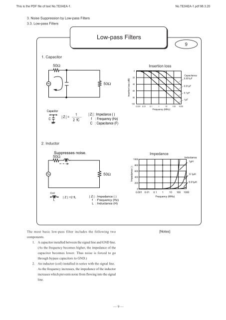
This is the PDF file of text No.TE04EA-1. No.TE04EA-1.pdf 98.3.203. Noise Suppression by <strong>Low</strong>-<strong>pass</strong> <strong>Filters</strong>3.3. <strong>Low</strong>-<strong>pass</strong> <strong>Filters</strong>Filter Construction - Constantand Insertion Loss10Changing the constant of filters (capacitance or inductance)Increasing the number of filter elementsCapacitorCoilL-typeL-typeInsertion lossInsertion loss20dB20dB20dB40dB40dB40dB0.1 1 10 100FrequencyInsertion loss20dB20dB20dB0.1 1 10 100FrequencyIf the filter constant was increased by 10times, the insertion loss angle does notchange. However, the insertion loss isincreased by 20 dB across the entirefrequency.Ratio ofconstant0.110 10.1 1 10 100Frequencyπ-typeT-typeInsertion loss60dB60dB60dB0.1 1 10 100FrequencyThe angle of insertion loss increasesby 20 dB/decade every time onefilter element is added.In the frequency band where EMI noise problems occur, theinsertion loss of filters increases by 20 dB every time the frequencyis multiplied by ten.When the constant of filters (capacitor’s capacitance or inductor’sinductance) is increased, the insertion loss of filters increases by20 dB every time the constant is multiplied by ten.To increase the angle of the insertion loss, filters are used incombination.[Notes]–– 10 ––
This is the PDF file of text No.TE04EA-1. No.TE04EA-1.pdf 98.3.203. Noise Suppression by <strong>Low</strong>-<strong>pass</strong> <strong>Filters</strong>3.4. Suitable Filter for Input/Output ImpedanceSuitable Filter for Input/OutputImpedance11HighOutput impedance (Zo)<strong>Low</strong>INOUTInput impedance (Zi)<strong>Low</strong> HighCapacitorINOUTπ-typeL-typeL-typeCoilT-typeInput impedanceZiFilterZoOutput impedanceFilter effect varies depending on the input/output impedances.As mentioned earlier, the insertion loss is measured with inputand output impedances of 50 Ω . However, actual circuitimpedances are not 50 Ω. Actual filter effects vary depending onthe impedances of the circuit where the filter is installed.Generally, a capacitor is more effective in suppressing noise inhigh impedance circuits, while an inductor is more effective inlow impedance circuits.[Notes]–– 11 ––