Accurate 3D Footwear Impression Recovery From Photographs
Accurate 3D Footwear Impression Recovery From Photographs
Accurate 3D Footwear Impression Recovery From Photographs
- No tags were found...

Create successful ePaper yourself
Turn your PDF publications into a flip-book with our unique Google optimized e-Paper software.
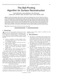
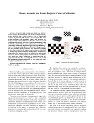
<strong>Accurate</strong> <strong>3D</strong> <strong>Footwear</strong> <strong>Impression</strong> <strong>Recovery</strong> <strong>From</strong> <strong>Photographs</strong>Fernanda A. Andaló ∗ , Fatih Calakli + , Gabriel Taubin + , and Siome Goldenstein ∗∗ Institute of Computing, University of Campinas (Unicamp), Campinas, SP, Brazil+ School of Engineering, Brown Univesity, Providence, RI, USAKeywords: Computational Forensics, <strong>Footwear</strong> impressionrecovery, Shoe print, Multiview stereo.AbstractThe recovery of footwear impression in crime scenes plays animportant role in investigations to corroborate or refute information,or to narrow down the number of suspects. Casting <strong>3D</strong>footwear impressions is a long-standing standard to obtain the<strong>3D</strong> models of the prints, slowly being replaced by a less invasivemethod, <strong>3D</strong> scanning. In this paper, we present an alternativemethod based on multiview stereo that yields an accurate<strong>3D</strong> model and provides some benefits over existing methods.We evaluate the results comparing our reconstructed <strong>3D</strong> modelswith the ones acquired by <strong>3D</strong> scanning. We also examinethe advantages and drawbacks of each method.1 IntroductionAn efficient crime investigation depends on the collection andanalysis of various kinds of evidence – items or informationgathered at the crime scene, or related locations, that are relevantto the investigation – which include DNA, tire tracks,fingerprints, shoe prints, bloodstains, among others.<strong>Impression</strong> evidence, such as footprints, tire tracks, andtool marks, are an important and common source of physicalevidence that can be used to corroborate or refute informationprovided by witnesses or suspects. According to a study conductedin Switzerland, shoe prints can be found in approximately35% of all crime scenes [1].Shoe prints can indicate whether a person was walking orrunning, was carrying something heavy or was unfamiliar withthe area or unsure of the terrain [2]. They can provide additionalinformation about the wearer, such as weight, height, andwear patterns that can be compared with a suspect’s shoes. Thelocation of the impressions at the scene can also often help inthe reconstruction of the crime [1].Shoe prints can be classified in three categories, based onhow they are found at the crime scene: patent, plastic, or latent[3]. Patent shoe prints are those that are clearly visible atthe crime scene; plastic or three-dimensional (<strong>3D</strong>) prints occurwhen the shoe sinks in the material that is being stepped on,leaving marks; and latent prints are invisible to the naked eyeand need to be exposed using different forensic techniques.Plastic or <strong>3D</strong> footwear impressions have depth in additionto length and width, and are most commonly found outdoorsin soil, sand, and snow [1]. The details that can be retainedand captured depend on the material texture, composition, andconditions, and these attributes can largely vary.In recent years, the standard method for capturing these <strong>3D</strong>prints is by casting using materials such as dental stone [1] orplaster [2], and photographing the print to provide additionaldetails which are taken into consideration later. The producedcast can be compared with manufactures’ shoes [2] or analyzedin search of minutiae that can provide information about thewearer.Just as shoe prints, each type of evidence requires a differentforensic technique to be revealed, captured and analyzed.These techniques have been improving over the lastyears due to reliability of modern technology and the greateruse of computational forensics. For example, pattern recognitionand other computational methods can reduce the bias inherentin traditional criminal forensics [4]. In this sense, anever growing system to collect evidence is <strong>3D</strong> scanning. It isuseful not only in collecting, but also in organizing evidenceand providing an analysis tool.BundlerPMVSSSDFigure 1. <strong>3D</strong> footwear impression recovery pipeline. <strong>Photographs</strong>taken at different viewpoints are used as input.Bundler recovers camera parameters for each image. PMVSgenerates a dense point cloud. SSD reconstructs the surface.
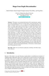
(a) Examples of input images.(b) <strong>3D</strong> point cloud.(c) Reconstructed <strong>3D</strong> model.Figure 2. <strong>3D</strong> footwear impression recovery pipeline: (a) capture several photographs of the shoe print with a digital camera; (b)reconstruct a dense point cloud; (c) reconstruct a surface.In this paper, we propose an alternate solution to the problemof capturing <strong>3D</strong> footwear prints at crime scenes. We compareit to the existing solutions: casting and <strong>3D</strong> scanning, andwe consider their advantages and drawbacks. Our solution includesa pipeline (Figure 1) to obtain the <strong>3D</strong> reconstructionusing only digital photographs taken from the footwear print atthe crime scene. The pipeline consists of three previously proposedmethods that together reconstruct a complete <strong>3D</strong> modelfrom a collection of images taken at different camera viewpoints(Figure 2(a)). The first step is to recover a set of cameraparameters and <strong>3D</strong> locations for keypoints in each image usingBundler [5], a method proposed to perform structure from motion(SfM) on unordered image collections. The second step isto generate a dense point cloud using PMVS [6], a patch-basedmultiview stereo method (Figure 2(b)). The last step is to reconstructthe surface using a new method called Smooth SignedDistance (SSD) [7] (Figure 2(c)).The main contributions of this paper are the pipeline to obtain<strong>3D</strong> models of footwear prints from pictures taken at differentangles, and the analysis of the results in respect to accuracyand its advantages over the existing methods.2 Background on <strong>3D</strong> footwear impressionrecoverySeveral decades ago, casting was the main method for recovering<strong>3D</strong> footwear impression evidence. Although the impressionswere also photographed, the less sophisticated equipmentmade photography not convenient and often less successfulthan casting. The casting material at the time, plaster ofParis, also induced a time consuming and messy casting procedure[1].<strong>From</strong> the 60s to the 80s, photography equipment and filmimproved, allowing photography to became a much more popularoption than casting. Many departments completely discontinuedplaster casts. However, in recent years, many qualitycasting materials and more simplified procedures changedcasting into an easier and convenient way of recovering <strong>3D</strong> impressionevidence [1].Together with this recent casting trend, High DefinitionSurveying (HDS), or <strong>3D</strong> scanning, became popular for surveyingbuildings, terrain, and other architectural features in a fastand detailed manner [8]. There are two types of <strong>3D</strong> scannersemployed in forensics: crime scene scanners that can capturea large overview map of the scene; and close-up <strong>3D</strong> scannersthat can capture individual objects in full color and high resolution[9]. Tire tracks, footprints, shoe prints, and bones, forexample, can be scanned in place with this last type of scanner[8].The use of <strong>3D</strong> scanning over casting is beneficial. Casting,in some cases, can destroy the original evidence in theprocess, while <strong>3D</strong> scanners often use lasers that can scan theobject without touching or affecting it. Some scanners alsocapture the color surface, producing a visually accurate replicathat would not be possible with casts. Furthermore, casts arephysical objects that are difficult to share across locations and
take up physical storage space [9]. It is also important to highlightthat creating a complete and highly detailed <strong>3D</strong> model ofa footprint takes less than 15 minutes, which is 125% fasterthan traditional methods of casting [9].Aside from acquisition speed, <strong>3D</strong> scanners are particularlywell suited for scanning organic shapes and highly curved surfacesthat would otherwise be difficult to measure [8]. Themain disadvantage is that <strong>3D</strong> scanners are not always appropriateto scan all kinds of surfaces and materials. Introducing anew kind of expensive equipment as a standard can also taketime and it will not always be available at all locations.The use of <strong>3D</strong> scanners in practice and in works related toforensics is growing together with a field called ComputationalForensics. CF is an emerging interdisciplinary research domainand it is understood as the hypothesis-driven investigation ofa specific forensic problem using computers, with the primarygoal of discovery and advancement of forensic knowledge [10].Several works contribute to the field of ComputationalForensics, such as automatic shoe print image retrieval [11, 12],latent palmprint matching [13], estimation of heights of objectsand persons in a single image [14], <strong>3D</strong> visualization of crimescenes [15], digital image and video forensics [16], and manyothers. We can see by these works that Computer vision andForensics are a powerful combination to the recovery and examinationof evidences, and it tends to grow as more scientificevaluation is available.In this work, we provide a new insight for footwear printcapturing that uses a Computer vision method, multiviewstereo, and that has some advantages over the current solutions.Multiview stereo methods require photographs of an objectat different camera viewpoints. They compute correspondencesbetween image pairs and a depth estimation for eachcamera viewpoint. By combining these estimates, multiviewstereo methods can provide a final <strong>3D</strong> model of the object. Asimilar approach has been applied successfully to recover dinosaurfootprints [17]. Table 1 summarizes the three discussedmethodologies: casting, <strong>3D</strong> scanning, and multiview stereo.3 Photo to <strong>3D</strong> PipelineThe proposed pipeline uses as input a set of photographs ofthe footwear impression, taken in different viewpoints aroundthe evidence (Figure 2(a)), then generates a <strong>3D</strong> point cloud(Section 3.1) which is used later to obtain a <strong>3D</strong> surface (Section3.2).3.1 <strong>From</strong> photos to point cloudThe goal of multi-view stereo (MVS) is to reconstruct a <strong>3D</strong>model from images taken from known camera viewpoints. Tolearn the viewpoints, we use Bundler [5] which takes a setof images as input and accurately estimates the camera viewpointper each image. Bundler first finds feature points (keypoints)in each input image. Each keypoint is associated witha local descriptor. The method then matches keypoint descriptorsbetween each pair of images, using an approximate nearestneighbors approach, then robustly estimates a fundamentalmatrix for the pair. After finding a set of consistent matchesbetween each image pair, the method organizes these matchesinto tracks of connected matching keypoints across multiplesimages, then recovers a set of camera parameters and a <strong>3D</strong> locationfor each track by minimizing the sum of distances betweenthe projections of each track and its corresponding imagefeatures.We then use the Patch-based MVS (PMVS) [6] algorithmwhich takes the same set of images and the estimated cameraparameters as input and produces <strong>3D</strong> models with accuracynearly comparable with laser scanners [18]. The algorithm isbased on the idea of correlating measurements from several imagesat once to derive <strong>3D</strong> surface information. It reconstructsa global <strong>3D</strong> model by using all the images available simultaneously.3.2 Surface reconstructionPMVS is also able to estimate a surface normal vector associatedfor each <strong>3D</strong> point measurement, and as a result, producea collection of so-called oriented points. Dense oriented pointclouds have become a pervasive surface representation [19] dueits simplicity and storage efficiency. However, since they do notconstitute surfaces, they cannot be used to make certain measurementsrequired by many applications in forensics.The problem of reconstructing surfaces from orientedpoints has a long history [20]. Poisson Surface Reconstruction[21] has become a leading contender due to its high qualityreconstructions. However, it is reported in a recent benchmarkstudy [22] that this method tends to oversmooth the data. Alternatively,we use Smooth Signed Distance (SSD) Surface Reconstruction[7] which does not suffer from oversmooting, andstill produces good quality surfaces. In fact, in many cases presentedin [7], SSD constructs surfaces with less error than someprior art methods including Poisson Surface Reconstruction.In SSD, oriented data points are regarded as samples of asmooth signed distance field f, and the surface S is definedby an implicit equation S = {x : f(x) = 0}. The implicitfunction f is estimated by minimizing the following energyE(f) =N∑f(p i ) 2 + λ 1i=1+ λ 2∫VN ∑i=1‖∇f(p i ) − n i ‖ 2‖Hf(x)‖ 2 dx (1)where ∇f(x) is the gradient of f(x), Hf(x) is the Hessian off(x), {(p 1 , n 1 ), . . . , (p N , n N )} are point-normal data pairs, Vis a bounding volume, and {λ 1 , λ 2 } are regularization parameters.A simple finite-difference discretization reduces the problemto solving sparse linear systems of equations.In our experiments, we efficiently converted oriented pointclouds into accurate polygon meshes using SSD reconstructionmethod (Figure 2(c)).4 Experimental resultsThe experiments consisted on the comparison of our proposedpipeline with one of the methods used in practice, <strong>3D</strong> scan-
Special materialsCasting <strong>3D</strong> Scanning Multiview stereoDental stone or other qualitymaterialsame camera already used<strong>3D</strong> scanner A camera. It can be thein crime scene investigationsTime for acquisition ∼ 30min [9] ∼ 15min [9] ∼ 5minPost acquisition work Transportation to the analysislocationDepends on the scanner.The model can be ready tobe analyzed or it may needto be processedIntrusiveness It may destroy the evidence None NoneGood scenarios The material cannot be too Not all materials are suitablesoftfor being scannedPipeline presented in thisworkThere is no limitation, aslong as the examiner cantake pictures at differentviewpointsAccuracy in these scenarios High High Medium to high*Table 1. Comparison between footwear prints recovery. (*) The accuracy is analyzed in Section 4.ning, with respect to the recovery of various footwear prints insand. We set up a sandbox with an attached <strong>3D</strong> scanner, wherewe produced footwear marks with four different types of shoes(Figure 3(a)). We used two pieces of equipment in our experiments:• NextEngine <strong>3D</strong> Laser Scanner with a point and texturedensity on target surface of 150 DPI, and the dimensionalaccuracy of ±0.015".• Digital camera Canon EOS Rebel XSi with 12.2-megapixel sensor and Canon EF-S 18-55mm f/3.5–5.6IS lenses, without the use of flash and with automaticfocus.We first set up the scanner at a distance of 31.5" from thesand in the box. For each footwear print, we first scanned itand then we took twelve photographs rotating around it (Figure3(b)), approximately in equal sized angles. For comparisonpurposes, we also scanned the four shoe soles corresponding tothe prints (Figure 3(c)).The twelve images of each shoe print were used as inputto our pipeline, generating complete <strong>3D</strong> reconstructions. Thescanned shoe prints and our generated <strong>3D</strong> models were registeredwith the corresponding shoe soles using Meshlab 1 . Toevaluate the quality of the generated <strong>3D</strong> models, we adoptedthe Haursdoff distance computed by Metro tool [23].We consider as groundtruth the distance map d g that representsthe computation of Haursdoff distance for the vertices ofthe shoe print scan in relation to the vertices of the shoe solescan. Note that d g is subjective to the curvature of the shoesole while the shoe is not being used and consequently not flatwith respect to the ground. In the same fashion, we computedthe distance map d m between our <strong>3D</strong> model and the shoe solescan. The value (d m − d g ) measures the quality of our model1 http://meshlab.sourceforge.net/compared to <strong>3D</strong> scanning, where d g and d m are the mean valuesof the distances in d g and d m , respectively 2 .Figure 4 shows the two obtained <strong>3D</strong> models for the firstshoe print (with the <strong>3D</strong> scanner and with our pipeline) and alsothe proposed evaluation. Figures 4(c) and 4(d) illustrate thedistance maps d g and d m , where red represents the minimumdistance and blue represents the maximum distance. Figure 5shows the same results for the third shoe print.By analyzing Figures 4 and 5, we can see that our methodis able to capture comparable amount of details, and the samefact can also be deduced by analyzing the value (d m − d g )computed for each shoe print (Table 2).Shoeprint # d g d m (d m − d g )1 9.996 10.002 0.0062 8.157 8.660 0.5033 8.715 9.480 0.7654 8.816 9.114 0.298Table 2. Evaluation of obtained <strong>3D</strong> model for each shoe printusing Haursdoff distance in millimeters.5 ConclusionIn this work, we presented a pipeline to recover footwear impressionfrom crime scenes based on a well known techniquein Computer Vision, multiview stereo, which has not been consideror analyzed for this kind of application in the literatureuntil now. Despite the simplicity for set up and acquisition, thereconstructed surfaces proved to be comparable with <strong>3D</strong> scan-2 In most works that adopt Haursdoff distance, researchers considernot the mean but the maximum value of the map. In our work, themaximum value does not represent a good value for comparison, sinceit always appears outside the print, where we don’t expect the methodto be accurate. To illustrate this, please refer fo Figure 4(d).
(a) (b) (c)Figure 3. (a) Sandbox with attached <strong>3D</strong> scanner. (b) Twelve photographs taken from the first shoe print. (c) Shoe soles scans.ning, a high-end technology used in practice, providing accurate<strong>3D</strong> models of the shoe prints. A digital camera is the onlyequipment required to recovery the evidence, which makes theprocess convenient and fast.AcknowledgementsThis work is primarily supported by CNPq grant 201238/2010-1, with additional funding from NSF grants IIS–0808718,CCF–0729126, and CCF–0915661.References[1] W. Bodziak, <strong>Footwear</strong> impression evidence: detection,recovery, and examination. USA: CRC Press, 2nd ed.,2000.[2] K. Hess and C. Orthmann, Criminal Investigation. USA:Delmar Cengage Learning, 9th ed., 2010.[3] Australian School Innovation in Science, Technologyand Mathematics Project, “<strong>Impression</strong>s – introduction totracks, footprints and plaster casts.” Course Lecture.[4] S. Srihari, “Beyond CSI: The Rise of ComputationalForensics,” IEEE Spectrum, pp. 38–43, 2010.[5] N. Snavely, S. Seitz, and R. Szeliski, “Photo tourism: exploringphoto collections in <strong>3D</strong>,” in ACM Transactions onGraphics, vol. 25, pp. 835–846, 2006.[6] Y. Furukawa and J. Ponce, “<strong>Accurate</strong>, dense, and robustmulti-view stereopsis,” IEEE Trans. Pattern Anal. Mach.Intell., vol. 32, no. 8, 2009.[7] F. Calakli and G. Taubin, “SSD: Smooth Signed DistanceSurface Reconstruction,” Computer Graphics Forum,vol. 30, no. 7, 2011. http://mesh.brown.edu/ssd/.[8] E. Liscio, “A Primer on <strong>3D</strong> Scanning in Forensics,”Forensic Magazine, 2009.[9] P. DeLaurentis, “<strong>3D</strong> Scanning: A New Tool for CrackingTough Cases,” Forensic Magazine, vol. 6, no. 1, pp. 37–40, 2009.[10] K. Franke and S. Srihari, “Computational forensics: Anoverview,” Computational Forensics, pp. 1–10, 2008.[11] L. Zhang and N. Allinson, “Automatic shoeprint retrievalsystem for use in forensic investigations,” in Proc. ofthe 2005 UK Workshop on Computational Intelligence,pp. 137–142, 2005.[12] G. AlGarni and M. Hamiane, “A novel technique for automaticshoeprint image retrieval,” Forensic science Inter.,vol. 181, no. 1-3, pp. 10–14, 2008.[13] A. Jain and J. Feng, “Latent palmprint matching,” IEEETrans. Pattern Anal. Mach. Intell., pp. 1032–1047, 2008.[14] F. A. Andaló, G. Taubin, and S. Goldenstein, “Detectingvanishing points by segment clustering on the projectiveplane for single-view photogrammetry,” in IEEE InternationalWorkshop on Information Forensics and Security,pp. 1–6, 2010.[15] M. Ma, H. Zheng, and H. Lallie, “Virtual Reality and <strong>3D</strong>Animation in Forensic Visualization,” Journal of forensicsciences, 2010.[16] A. Rocha, W. S. T. Boult, and S. Goldenstein, “Vision ofthe unseen: Current trends and challenges in digital imageand video forensics,” ACM Computing Surveys, 2011.[17] F. Remondino, A. Rizzi, S. Girardi, F. Petti, andM. Avanzini, “<strong>3D</strong> ichnology – recovering digital <strong>3D</strong> modelsof dinosaur footprints,” The Photogrammetric Record,vol. 25, no. 131, pp. 266–282, 2010.
(a) Shoe print scan. (b) Our <strong>3D</strong> model. (c) Groundtruth d g. (d) Our result d m.Figure 4. Acquired data and evaluation for the first shoe print. In (c) and (d), red represents the minimum distance and bluerepresents the maximum distance.(a) Shoe print scan. (b) Our <strong>3D</strong> model. (c) Groundtruth d g. (d) Our result d m.Figure 5. Acquired data and evaluation for the third shoe print. The <strong>3D</strong> models in (a) and (b) are displayed without texture forbetter visualization. In (c) and (d), red represents the minimum distance and blue represents the maximum distance.[18] S. M. Seitz, B. Curless, J. Diebel, D. Scharstein, andR. Szeliski, “A comparison and evaluation of multi-viewstereo reconstruction algorithms,” in Proc. of the 2006IEEE Computer Society Conference on Computer Visionand Pattern Recognition, pp. 519–528, 2006.[19] L. Kobbelt and M. Botsch, “A Survey of Point-BasedTechniques in Computer Graphics,” Computers & Graphics,vol. 28, no. 6, pp. 801–814, 2004.[20] O. Schall and M. Samozino, “Surface from scatteredpoints: A brief survey of recent developments,” in 1st InternationalWorkshop on Semantic Virtual Environments,pp. 138–147, 2005.[21] M. Kazhdan, M. Bolitho, and H. Hoppe, “Poisson surfacereconstruction,” in Proc. of the 4th Eurographics Symposiumon Geometry Processing, pp. 61–70, 2006.[22] M. Berger, J. Levine, L. Nonato, G. Taubin, and C. Silva,“An End-to-End Framework for Evaluating Surface Reconstruction,”SCI Technical Report, University of Utah,Jan. 2011.[23] P. Cignoni, C. Rocchini, and R. Scopigno, “Metro: measuringerror on simplified surfaces,” in Computer GraphicsForum, vol. 17, pp. 167–174, 1998.