A Comprehensible GloMoSim Tutorial - Sm.luth.se
A Comprehensible GloMoSim Tutorial - Sm.luth.se
A Comprehensible GloMoSim Tutorial - Sm.luth.se

Create successful ePaper yourself
Turn your PDF publications into a flip-book with our unique Google optimized e-Paper software.
• FTP 0 1 10 0S. Node 0 <strong>se</strong>nds node 1 ten items at the start of the simulation, with the size of eachitem randomly determined by tcplib.• FTP 0 1 0 100S. Node 0 <strong>se</strong>nds node 1 the number of items randomly picked by tcplib after 100<strong>se</strong>conds into the simulation. The size of each item is also randomly determined by tcplib.FTP/GENERIC does not u<strong>se</strong> tcplib to simulate file transfer. Instead, the client simply <strong>se</strong>nds the dataitems to the <strong>se</strong>rver without the <strong>se</strong>rver <strong>se</strong>nding any control information back to the client. In order to u<strong>se</strong>FTP/GENERIC, the following format is needed:FTP/GENERIC where is the client node, is the <strong>se</strong>rver node, is how many applicationlayer items to <strong>se</strong>nd, is size of each application layer item, is when to startFTP/GENERIC during the simulation, and is when to terminate FTP/GENERIC. If is <strong>se</strong>t to 0, FTP/GENERIC will run until the specified or until the end of the simuation,which ever comes first. If is <strong>se</strong>t to 0, FTP/GENERIC will run until all istransmitted or until the end of simulation, which ever comes first. If and areboth greater than 0, FTP/GENERIC will run until either is done, is reached,or the simulation ends, which ever comes first. Some examples are• FTP/GENERIC 0 1 10 1460 0S 600S. Node 0 <strong>se</strong>nds node 1 ten items of 1460B each at the startof the simulation up to 600 <strong>se</strong>conds into the simulation. If the ten items are <strong>se</strong>nt before 600 <strong>se</strong>cond<strong>se</strong>lap<strong>se</strong>d, no other items are <strong>se</strong>nt.• FTP/GENERIC 0 1 10 1460 0S 0S. Node 0 <strong>se</strong>nds node 1 ten items of 1460B each at the start ofthe simulation until the end of the simulation. If the ten items are <strong>se</strong>nt the simulation ends, no otheritems are <strong>se</strong>nt.• FTP/GENERIC 0 1 0 1460 0S 0S. Node 0 continuously <strong>se</strong>nds node 1 items of 1460B each at thestart of the simulation until the end of the simulation.TELNET u<strong>se</strong>s tcplib to simulate the telnet protocol. In order to u<strong>se</strong> TELNET, the following format isneeded:TELNET where is the client node, is the <strong>se</strong>rver node, is how long the telnet<strong>se</strong>ssion will last, is when to start TELNET during the simulation. If is<strong>se</strong>t to 0, TELNET will u<strong>se</strong> tcplib to randomly determine how long the telnet <strong>se</strong>ssion will last. The intervalbetween telnet items are determined by tcplib. Some examples are• TELNET 0 1 100S 0S. Node 0 <strong>se</strong>nds node 1 telnet traffic for a duration of 100 <strong>se</strong>conds at the startof the simulation.• TELNET 0 1 0S 0S. Node 0 <strong>se</strong>nds node 1 telnet traffic for a duration randomly determined by tcplibat the start of the simulation.CBR simulates a constant bit rate generator. In order to u<strong>se</strong> CBR, the following format is needed:CBR 7
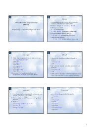
CBATHE HIDDEN TERMINALPROBLEMDSTOPC A BTHE EXPOSEDTERMINALPROBLEMFigure 2: The Hidden and Expo<strong>se</strong>d Terminal Problems# MOBILITY-TRACE-FILE ./mobility.in# MOBILITY PATHLOSS-MATRIX# The following parameter is necessary for# all mobility modelsMOBILITY-POSITION-GRANULARITY 0.5# Example of MOBILITY.IN file# mobility trace format: node-address simclock destination(x y z)# All lines for a node must be sorted in time increasing order.10 100S (200.0, 150.0, 0.2)10 200S (200.0, 150.0, 0.2)10 500S (250.0, 250.0, 0.2)3 Some Simulation Examples3.1 MAC protocols SimulationGlomosim has <strong>se</strong>veral MAC protocols to be u<strong>se</strong>d in a simulation, such as CSMA, MACA and 802.11. InCSMA (Carrier Sen<strong>se</strong> Multiple Access) protocol, a station wishing to transmit, first listen to the mediumin order to determine if another transmission is in progress (carrier <strong>se</strong>n<strong>se</strong>). If the transmission medium isin u<strong>se</strong>, the station waits, otherwi<strong>se</strong> it may transmit. Unfortunately, CSMA is limited by two interferencemechanisms: the hidden and the expo<strong>se</strong>d terminal problems. The hidden terminal problem occurs becau<strong>se</strong>the radio network, as oppo<strong>se</strong>d to other networks, such as a LAN, does not guarantee high degree of connectivity.Thus, two nodes, which maintain connectivity to a third node, do not necessarily, can hear eachother. In Fig. [ 2] node A is in communication with node B where A is currently transmitting. Node Cwishes to communicate with node B as well. Following the CSMA protocol, node C listens to the medium,but since C does not detect node’s A transmission, it declares the medium free. Con<strong>se</strong>quently, C acces<strong>se</strong>sthe medium, causing collisions at B.The <strong>se</strong>cond problem also shown at Fig. [ 2], the expo<strong>se</strong>d terminal occurs when for example, node A istransmitting to node B, while node C wants to transmit D. Following the CSMA protocol, node C listensto the medium, hears that node A transmits and defers from accessing the medium. However, there is no13
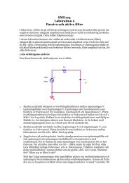
TRTRABRTS (Request To Send)Neighbors of Transmitter are silencedData is <strong>se</strong>ntTRTCTS (Clear To Send)Neighbors of Receiver are silencedRTRACK is returnedInterference iftransmission rangesare not commonIEEE 802.11 MAC HANDSHAKEFigure 3: The RTS/CTS dialoguereason why node C cannot transmit concurrently with the transmission of node A, as the transmission ofnode C would not interfere with the reception at node B due to the distance between the two. The pointhere is, again, the fact that the collisions occur at the receiver, while the CSMA protocol checks the statusof the medium at the transmitter.In general, the hidden terminal problem reduces the capacity of a network due to increasing the numberof collisions, while the expo<strong>se</strong>d terminal problem reduces the network capacity due to the unnecessarilydeferring nodes from transmitting. Several attempts have been made in the literature to reduce the effectof the<strong>se</strong> two problems. The necessity of a dialogue between the transmitting and the receiving nodes thatpreempts the actual transmission and that is referred to as the RTS/CTS dialogue, has generally accepted.In the RTS/CTS dialogue example (Fig. [ 3]), a node ready to transmit a packet, <strong>se</strong>nd a short controlpacket, the Request To Send (RTS), with all nodes that hear the RTS defer from accessing the channel forthe duration of the RTS/CTS dialogue. The destination, upon reception of the RTS responds with anothershort control packet, the Clear To Send (CTS) [9].All nodes that hear the CTS packet defer from accessing the channel for the duration of the data packettransmission. The reception of the CTS packet at the transmitting node acknowledges that the RTS/CTSdialogue has been successful and the node starts the transmission of the actual data packet. In the eventthat two nodes <strong>se</strong>nd simultaneous RTS frames to the same node, the RTS transmissions collide and are lost.If this occurs, the nodes which <strong>se</strong>nt the unsuccessful RTS packets <strong>se</strong>t a random timer utilizing the binaryexponential backoff algorithm for the next transmission attempt. Although the RTS/CTS dialogue does noteliminate the hidden and the expo<strong>se</strong> terminal problems, it does provide some degree of improvement overthe traditional CSMA schemes. Nevertheless, the RTS/CTS dialogue can fail when nodes have differenttransmission ranges.The MACA (Multiple Access Collision Avoidance) and the 802.11 protocols u<strong>se</strong> the described RTS/CTSdialogue for collision avoidance on the shared channel. Where IEEE 802.11 differs however, is in its requirementof an acknowledgment (ACK) transmission by the receiver after the successful reception of the datapacket. The inclusion of the ACK allows immediate retransmission if necessary by verifying that the datapacket was successfully received.3.1.1 Example 1: The Hidden Terminal ProblemIn the following example, three nodes are within communication range. Node 0 starts <strong>se</strong>nding data packetsto node 1 after node 2 starts <strong>se</strong>nding data packets to node 1. The configuration parameters for this scenarioare the following:14
In app.conf: CBR 0 1 0 512 4MS 6MS 0CBR 2 1 0 512 4MS 0 0Node: 0, Layer: MacMACA, Number of UNICAST packets output to the channel: 162Node: 0, Layer: MacMACA, Number of RTS Packets <strong>se</strong>nt: 4779Node: 0, Layer: MacMACA, Number of CTS Packets <strong>se</strong>nt: 1Node: 0, Layer: MacMACA, Number of RTS Packets got: 1Node: 0, Layer: MacMACA, Number of CTS Packets got: 162Node: 0, Layer: MacMACA, Number of Noisy Packets got: 135Node: 0, Layer: AppCbrClient, (0) Server address: 1Node: 0, Layer: AppCbrClient, (0) Total number of bytes <strong>se</strong>nt: 639488Node: 0, Layer: AppCbrClient, (0) Total number of packets <strong>se</strong>nt: 1249Node: 1, Layer: MacMACA, Number of UNICAST packets received clearly: 281Node: 1, Layer: MacMACA, Number of RTS Packets <strong>se</strong>nt: 40Node: 1, Layer: MacMACA, Number of CTS Packets <strong>se</strong>nt: 2055Node: 1, Layer: MacMACA, Number of RTS Packets got: 2055Node: 1, Layer: MacMACA, Number of CTS Packets got: 2Node: 1, Layer: AppCbrServer, (0) Client address: 0Node: 1, Layer: AppCbrServer, (0) Total number of bytes received: 75264Node: 1, Layer: AppCbrServer, (0) Total number of packets received: 147Node: 1, Layer: AppCbrServer, (0) Client address: 2Node: 1, Layer: AppCbrServer, (0) Total number of bytes received: 68608Node: 1, Layer: AppCbrServer, (0) Total number of packets received: 134Node: 2, Layer: MacMACA, Number of UNICAST packets output to the channel: 144Node: 2, Layer: MacMACA, Number of RTS Packets <strong>se</strong>nt: 4800Node: 2, Layer: MacMACA, Number of CTS Packets <strong>se</strong>nt: 1Node: 2, Layer: MacMACA, Number of RTS Packets got: 1Node: 2, Layer: MacMACA, Number of CTS Packets got: 144Node: 2, Layer: MacMACA, Number of Noisy Packets got: 149Node: 2, Layer: AppCbrClient, (0) Total number of bytes <strong>se</strong>nt: 640000Node: 2, Layer: AppCbrClient, (0) Total number of packets <strong>se</strong>nt: 1250And if we change to IEEE 802.11 MAC protocol, we obtain:In app.conf: CBR 0 1 0 512 4MS 6MS 0CBR 2 1 0 512 4MS 0 0Node: 0, Layer: 802.11, UCAST (non-frag) pkts <strong>se</strong>nt to chanl: 701Node: 0, Layer: 802.11, retx pkts due to CTS timeout: 44Node: 0, Layer: AppCbrClient, (0) Total number of bytes <strong>se</strong>nt: 639488Node: 0, Layer: AppCbrClient, (0) Total number of packets <strong>se</strong>nt: 1249Node: 1, Layer: 802.11, UCAST pkts rcvd clearly: 1425Node: 1, Layer: AppCbrServer, (0) Client address: 0Node: 1, Layer: AppCbrServer, (0) Total number of bytes received: 358912Node: 1, Layer: AppCbrServer, (0) Total number of packets received: 701Node: 1, Layer: AppCbrServer, (0) Client address: 2Node: 1, Layer: AppCbrServer, (0) Total number of bytes received: 370688Node: 1, Layer: AppCbrServer, (0) Total number of packets received: 724Node: 2, Layer: 802.11, UCAST (non-frag) pkts <strong>se</strong>nt to chanl: 724Node: 2, Layer: 802.11, retx pkts due to CTS timeout: 44Node: 2, Layer: AppCbrClient, (0) Total number of bytes <strong>se</strong>nt: 640000Node: 2, Layer: AppCbrClient, (0) Total number of packets <strong>se</strong>nt: 125016
Which shows that a better behavior is obtained when using CSMA instead of MACA becau<strong>se</strong> of theRTS/CTS messages. The u<strong>se</strong> of RTS packets whenever a source has a data packet to <strong>se</strong>nd without first<strong>se</strong>nsing the channel, results in an increa<strong>se</strong> in packet collisions and hence decrea<strong>se</strong>d throughput. The collisionavoidance mechanism incorporated into IEEE 802.11 for the transmission of fRTS packets aids in the reductionof the number of collisions. Con<strong>se</strong>quently, more data packets reach their destinations. The<strong>se</strong> results arealso obtained and confirmed in [10].3.1.2 Example 2: The Expo<strong>se</strong>d Terminal ProblemIn the following example, four nodes are within communication range. Node 1 starts <strong>se</strong>nding data packets tonode 0 after node 2 starts <strong>se</strong>nding data packets to node 3. We establish the packet inter-departure time verysmall, so that when node 1 wants to transmit, it <strong>se</strong>n<strong>se</strong>s the medium busy. The configuration parameters forthis scenario are the following:In nodes.input file:0 0 (50, 1000, 0.0)1 0 (650, 1000, 0.0)2 0 (1250, 1000, 0.0)3 0 (1850, 1000, 0.0)so the simulation model is:Node0----600m----Node1----600m----Node2----600m----Node3In config.in file:MOBILITY = NONESIMULATION-TIME = 5SPROPAGATION-PATHLOSS = FREE-SPACERADIO-TX-POWER = 15dBmRADIO-RX-SENSITIVITY = -81 dBmRADIO-RX-THRESHOLD = -81dBmANTENNA_GAIN = 0dBMAC_PROTOCOL = CSMAIf we let that only node 2 <strong>se</strong>nds data packets to node 3, while node 1 remains silence, we obtain thefollowing output in the glomo.stat file.In app.conf: CBR 2 3 0 512 4MS 0 0In glomo.stat:Node: 2, Layer: MacCSMA, Number of UNICAST packets output to the channel: 1250Node: 2, Layer: MacCSMA, Number of BROADCAST packets output to the channel: 1Node: 2, Layer: AppCbrClient, (0) Total number of bytes <strong>se</strong>nt: 640000Node: 2, Layer: AppCbrClient, (0) Total number of packets <strong>se</strong>nt: 1250Node: 3, Layer: MacCSMA, Number of UNICAST packets received clearly: 1250Node: 3, Layer: MacCSMA, Number of BROADCAST packets received clearly: 1Node: 3, Layer: AppCbrServer, (0) Total number of bytes received: 640000Node: 3, Layer: AppCbrServer, (0) Total number of packets received: 1250The number of packets to be <strong>se</strong>nt is (5S - 0)/ 4EXP(-3) S = 1250. That is, all packets that are <strong>se</strong>nt bynode 2 are clearly received by node 3. The same occurs if we let node 1 to transmit alone, but if we let bothnodes 1 and 2 to transmit at the same time, we have:In app.conf:17
CBR 1 0 0 512 4MS 4MS 0CBR 2 3 0 512 4MS 0 0In glomo.stat:Node: 0, Layer: MacCSMA, Number of UNICAST packets received clearly: 0Node: 0, Layer: MacCSMA, Number of BROADCAST packets received clearly: 0Node: 1, Layer: MacCSMA, Number of UNICAST packets output to the channel: 0Node: 1, Layer: MacCSMA, Number of BROADCAST packets output to the channel: 6Node: 1, Layer: MacCSMA, Number of UNICAST packets received clearly: 0Node: 1, Layer: MacCSMA, Number of BROADCAST packets received clearly: 1Node: 1, Layer: AppCbrClient, (0) Total number of bytes <strong>se</strong>nt: 639488Node: 1, Layer: AppCbrClient, (0) Total number of packets <strong>se</strong>nt: 1249Node: 2, Layer: MacCSMA, Number of UNICAST packets output to the channel: 1250Node: 2, Layer: MacCSMA, Number of BROADCAST packets output to the channel: 1Node: 2, Layer: AppCbrClient, (0) Total number of packets <strong>se</strong>nt: 1250Node: 2, Layer: AppCbrClient, (0) Throughput (bits per <strong>se</strong>cond): 1024000Node: 3, Layer: MacCSMA, Number of UNICAST packets received clearly: 1244Node: 3, Layer: MacCSMA, Number of BROADCAST packets received clearly: 1Node: 3, Layer: AppCbrServer, (0) Total number of bytes received: 636928Node: 3, Layer: AppCbrServer, (0) Total number of packets received: 1244which repre<strong>se</strong>nts node 2 transmitting to node 3 and all packets are received clearly by 3, node 1 startstransmitting 4 MS after start of simulation but does not <strong>se</strong>n<strong>se</strong> any carrier (although the application layerhas 1249 packets to transmit) and the MAC layer does not transmit almost any packet to the channel. If wechange the MAC protocol in the config.in file to MACA and let that only node 2 <strong>se</strong>nds packets to node 3,we obtain the following glomo.stat file:In app.conf:CBR 2 3 0 512 4MS 0 0Node: 2, Layer: MacMACA, Number of UNICAST packets output to the channel: 1220Node: 2, Layer: MacMACA, Number of RTS Packets <strong>se</strong>nt: 1220Node: 2, Layer: MacMACA, Number of CTS Packets <strong>se</strong>nt: 1Node: 2, Layer: MacMACA, Number of RTS Packets got: 1Node: 2, Layer: MacMACA, Number of CTS Packets got: 1220Node: 2, Layer: AppCbrClient, (0) Total number of bytes <strong>se</strong>nt: 624640Node: 2, Layer: AppCbrClient, (0) Total number of packets <strong>se</strong>nt: 1220Node: 3, Layer: MacMACA, Number of UNICAST packets received clearly: 1219Node: 3, Layer: MacMACA, Number of RTS Packets <strong>se</strong>nt: 1Node: 3, Layer: MacMACA, Number of CTS Packets <strong>se</strong>nt: 1220Node: 3, Layer: MacMACA, Number of RTS Packets got: 1220Node: 3, Layer: MacMACA, Number of CTS Packets got: 1Which shows that all packets <strong>se</strong>nt by node 2 are clearly received by node 3. If we let node 1 transmit tonode 0 and node 2 transmit to node 3 simultaneously, then we obtain the following glomo.stat file:In app.conf:CBR 1 0 0 512 4MS 4MS 0CBR 2 3 0 512 4MS 0 0Node: 0, Layer: MacMACA, Number of UNICAST packets received clearly: 41Node: 0, Layer: MacMACA, Number of BROADCAST packets received clearly: 1Node: 0, Layer: MacMACA, Number of RTS Packets <strong>se</strong>nt: 6418
Node: 0, Layer: MacMACA, Number of CTS Packets <strong>se</strong>nt: 3162Node: 0, Layer: MacMACA, Number of RTS Packets got: 3162Node: 0, Layer: MacMACA, Number of CTS Packets got: 1Node: 0, Layer: AppCbrServer, (0) Total number of bytes received: 20992Node: 0, Layer: AppCbrServer, (0) Total number of packets received: 41Node: 1, Layer: MacMACA, Number of UNICAST packets output to the channel: 721Node: 1, Layer: MacMACA, Number of BROADCAST packets output to the channel: 1Node: 1, Layer: MacMACA, Number of UNICAST packets received clearly: 1Node: 1, Layer: MacMACA, Number of BROADCAST packets received clearly: 1Node: 1, Layer: MacMACA, Number of RTS Packets <strong>se</strong>nt: 3842Node: 1, Layer: MacMACA, Number of CTS Packets <strong>se</strong>nt: 21Node: 1, Layer: MacMACA, Number of RTS Packets got: 21Node: 1, Layer: MacMACA, Number of CTS Packets got: 721Node: 1, Layer: MacMACA, Number of Noisy Packets got: 65Node: 1, Layer: AppCbrClient, (0) Total number of bytes <strong>se</strong>nt: 639488Node: 1, Layer: AppCbrClient, (0) Total number of packets <strong>se</strong>nt: 1249Node: 2, Layer: MacMACA, Number of UNICAST packets output to the channel: 770Node: 2, Layer: MacMACA, Number of BROADCAST packets output to the channel: 1Node: 2, Layer: MacMACA, Number of UNICAST packets received clearly: 1Node: 2, Layer: MacMACA, Number of BROADCAST packets received clearly: 0Node: 2, Layer: MacMACA, Number of RTS Packets <strong>se</strong>nt: 3837Node: 2, Layer: MacMACA, Number of CTS Packets <strong>se</strong>nt: 1Node: 2, Layer: MacMACA, Number of RTS Packets got: 1Node: 2, Layer: MacMACA, Number of CTS Packets got: 770Node: 2, Layer: MacMACA, Number of Noisy Packets got: 42Node: 2, Layer: AppCbrClient, (0) Total number of bytes <strong>se</strong>nt: 640000Node: 2, Layer: AppCbrClient, (0) Total number of packets <strong>se</strong>nt: 1250Node: 3, Layer: MacMACA, Number of UNICAST packets output to the channel: 1Node: 3, Layer: MacMACA, Number of BROADCAST packets output to the channel: 0Node: 3, Layer: MacMACA, Number of UNICAST packets received clearly: 52Node: 3, Layer: MacMACA, Number of BROADCAST packets received clearly: 1Node: 3, Layer: MacMACA, Number of RTS Packets <strong>se</strong>nt: 1Node: 3, Layer: MacMACA, Number of CTS Packets <strong>se</strong>nt: 3179Node: 3, Layer: MacMACA, Number of RTS Packets got: 3179Node: 3, Layer: MacMACA, Number of CTS Packets got: 1Node: 3, Layer: MacMACA, Number of Noisy Packets got: 0Node: 3, Layer: AppCbrServer, (0) Total number of bytes received: 26624Node: 3, Layer: AppCbrServer, (0) Total number of packets received: 52which shows that in an expo<strong>se</strong>d-terminal scenario, both CSMA and MACA protocols pre<strong>se</strong>nt a poorperformance behavior.3.2 Results AnalysisThe data generated in previous examples was small, allowing to do a direct analysis from the glomo.statfile. Nevertheless, in most ca<strong>se</strong>s this is not possible due to the size of the network and the duration of thesimulation time. In the<strong>se</strong> ca<strong>se</strong>s we u<strong>se</strong> other tools to do an analysis of the glomo.stat file. For example, thefollowing shell program# ./analy-datpak1.sh cat $1 | grep AppCbrServer | grep Total | grep packets |grep received19
obtains the number of data packets (at the application layer -or AppCbrServer) received by their destinations.An example of it when executed with the glomo.stat is the following:./analy-datpak1.sh cmpmac-802aodv-200.statNode: 3, Layer: AppCbrServer, (0) Total number of packets received: 404Node: 5, Layer: AppCbrServer, (0) Total number of packets received: 1115Node: 7, Layer: AppCbrServer, (0) Total number of packets received: 622Node: 9, Layer: AppCbrServer, (0) Total number of packets received: 260Node: 62, Layer: AppCbrServer, (0) Total number of packets received: 360Node: 65, Layer: AppCbrServer, (0) Total number of packets received: 338Node: 67, Layer: AppCbrServer, (0) Total number of packets received: 779Node: 69, Layer: AppCbrServer, (1) Total number of packets received: 1011Node: 70, Layer: AppCbrServer, (0) Total number of packets received: 922Node: 73, Layer: AppCbrServer, (0) Total number of packets received: 1079Node: 76, Layer: AppCbrServer, (0) Total number of packets received: 935Node: 79, Layer: AppCbrServer, (0) Total number of packets received: 939Node: 81, Layer: AppCbrServer, (0) Total number of packets received: 647Node: 83, Layer: AppCbrServer, (0) Total number of packets received: 632Node: 85, Layer: AppCbrServer, (0) Total number of packets received: 1184Node: 88, Layer: AppCbrServer, (0) Total number of packets received: 875Node: 90, Layer: AppCbrServer, (0) Total number of packets received: 988Node: 94, Layer: AppCbrServer, (0) Total number of packets received: 363Node: 95, Layer: AppCbrServer, (0) Total number of packets received: 1014Node: 96, Layer: AppCbrServer, (0) Total number of packets received: 874Other parameters such as Packet Data Ratio, Percentage of Loss Rate and Packets Sent by the sourcescan be obtained with the following shell and awk programs:Shell program:cat $1 | grep App | grep Total | grep packets | awk -f glomopak1.awkAWK program:BEGIN{sumcount<strong>se</strong>nt = 0;sumcountrcv = 0;}{if ($10 == "<strong>se</strong>nt:") sumcount<strong>se</strong>nt+= $11;el<strong>se</strong> if ($10 == "received:") sumcountrcv += $11;}END{printf("Loss Packet Percentage = %f \% \n", 100-((sumcountrcv*100)/sumcount<strong>se</strong>nt));printf("Packet Delivery Ratio = %f \n\n",sumcountrcv/sumcount<strong>se</strong>nt);printf("Packets Received = %d \n", sumcountrcv);printf("Packets Sent = %d \n\n", sumcount<strong>se</strong>nt);}An example of the execution of the<strong>se</strong> programs on the previous example is the following:./analy-datpak2.sh cmpmac-802aodv-200.statLoss Packet Percentage = 36.079167 %20
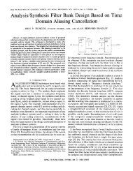
Packet Delivery Ratio = 0.639208Packets Received = 15341Packets Sent = 24000To obtain the Average Delay (in the ca<strong>se</strong> of CBR traffic) and the Control Packets generated by theAODV routing protocol, the following programs can be u<strong>se</strong>d:# program analy-delay1.shcat $1 | grep AppCbrServer | grep end-to-end | grep delay| awk -f delay1.awkwhere delay1 AWK program is:BEGIN{sumdelay = 0;countdelay = 0;}{}sumdelay += $10;countdelay++;END{printf("Average Delay = %f \n", sumdelay/countdelay);}-----------------------------------# program analy-routAODVctrl-1.shcat $1 | grep RoutingAodv | grep CTRL \| awk ’{sum += $11} END {print sum}’We can even obtain some interesting graphs from simulations. Lets suppo<strong>se</strong> we want to obtain a graphof the variance of packets delivered to final destination, with networks of different sizes (30, 50, 70, 100 and200 nodes) and with nodes move at different speeds (1, 5, 10 and 20 m/s). We can run <strong>se</strong>veral simulations(each with a specified node number and speed of the mobility model). To shorten the simulation time, thetests can be executed at the same time 2 , thus obtaining the following table.Speed 30 nodes 50 nodes 70 nodes 100 nodes 200 nodes1 12885 34940 56539 57514 673105 16927 33433 43038 36315 6872010 14393 22421 34559 34884 4461520 12108 20455 29128 27706 28297If the data of this table is u<strong>se</strong>d in a file (e.g mobil.txt), then we may u<strong>se</strong> graphic tools such as GnuPlotto obtain an appropriate graph. In the ca<strong>se</strong> of GnuPlot, we can execute the following commands to obtainthe graph repre<strong>se</strong>nted at Fig. [ 4] and contained in file nodedens12.eps.<strong>se</strong>t terminal postscript eps<strong>se</strong>t size 1/1., 1/1.2 In order to run <strong>se</strong>veral simulations simultaneously, <strong>se</strong>veral images of <strong>GloMoSim</strong> may be installed in different directories.At the end of each simulation, the results of the glomo.stat file have to be collected individually. The environment variables of<strong>GloMoSim</strong> have to be specified according to each ca<strong>se</strong>.21
BRMM7000030 nodes50 nodes70 nodes100 nodes200 nodes6000050000Packets400003000020000100000 5 10 15 20Speed (m/s)Figure 4: Number of Data Packets received by their destination<strong>se</strong>t title "BRMM"<strong>se</strong>t output "nodedens12.eps"<strong>se</strong>t xlabel "Speed (m/s)"<strong>se</strong>t ylabel "Packets"plot [0:20][8000:75000] "mobil22.txt" using 1:2 title ’30 nodes’ with linespoints, \"mobil.txt" using 1:3 title ’50 nodes’ with linespoints, \"mobil.txt" using 1:4 title ’70 nodes’ with linespoints, \"mobil.txt" using 1:5 title ’100 nodes’ with linespoints, \"mobil.txt" using 1:6 title ’200 nodes’ with linespoints4 Notes on Routing Protocols in <strong>GloMoSim</strong>4.1 AODV<strong>GloMoSim</strong> implements AODV ba<strong>se</strong>d on an older IETF draft (draft-ietf-manet-aodv-03.txt). The protocolassumes the MAC protocol <strong>se</strong>nds a signal to the routing protocol when it detects link breaks. MAC protocolssuch as IEEE 802.11 and MACAW have this functionality. In IEEE 802.11 for example, when no CTS isreceived after RTS, and no ACK is received after retransmissions of unicasted packet, it <strong>se</strong>nds the signal tothe routing protocol.If u<strong>se</strong>rs want to u<strong>se</strong> MAC protocols other than IEEE 802.11, they must implement schemes to detectlink breaks. A way to do this is, for example, using HELLO packets, as specified in AODV documents.Unsolicited RREPs are broadcasted and forwarded only if the node is part of the broken route and not thesource of that route. If more than one route u<strong>se</strong>s the broken link, multiple RREP messages are <strong>se</strong>nt.4.2 FSRFSR is ba<strong>se</strong>d on the premi<strong>se</strong> that changes in a network region’s topology have less effect on a router’s packetforwarding decisions as the distance (in hops) between the router and the network increa<strong>se</strong>s. FSR is anadaptation of GSR where instead of propagating information through the network by periodic exchanges, anode exchanges individual link state table entries at different rates depending on the distance to the link’ssource. Each update message does not contain information about all nodes. It exchanges information aboutclo<strong>se</strong>r nodes more frequently than it does about farther nodes thus reducing the update message size.Fig. [ 5] defines the scope of fisheye for the center node. The scope is defined as the <strong>se</strong>t of nodes thatcan be reached within a given number of hops; where three scopes are shown in the example. In <strong>GloMoSim</strong>,22
RETURN VALUE: Returns True if the queue is empty// ASSUMPTIONS: None.//For identation, each nested piece of code should be indented by four (4) spaces. TAB characters are notallowed and will be removed by the expand command. For emacs, put (<strong>se</strong>tq-default indent-tabs-mode nil) inthe .emacs file to eliminate TAB characters. Other recommendations are:• Complex expressions must match the parenthe<strong>se</strong>s level. Always u<strong>se</strong> braces on if/el<strong>se</strong>, while and forstatements.if (.....) {Statement}el<strong>se</strong> {Statement}• U<strong>se</strong> enumerated constants to give names to a <strong>se</strong>t of flags. for example:BAD:GOOD:#define INTEGER 0 typedef enum {#define CHAR 1 Integer,#define FLOAT 2 Char,#define DOUBLE 3 Float,Double} DataType;• Functions like bcopy() and bzero() are non-ANSI standard functions and should not be u<strong>se</strong>d. Insteadu<strong>se</strong> the functions memcpy() and mem<strong>se</strong>t() which are ANSI standard functions.5.2 Structure of <strong>GloMoSim</strong>After downloading and upzipping <strong>GloMoSim</strong>, it contains the following directories:/application/bin/doc/include/java gui/mac/main/network/radio/scenarios/tcplib/transportcontains code for the application layerfor executable and input/output filescontains the documentationcontains common include filescontains the visual toolcontains the code for the mac layercontains the basic framework designcontains the code for the network layercontains the code for the radio layercontains some example scenarioscontains libraries for TCPcontains the code for the transport layerDirectory main contains the basic framework to execute <strong>GloMoSim</strong>, which includes driver.pc file thatdefines the driver entity. Every Par<strong>se</strong>c program must include an entity called driver which <strong>se</strong>rves a purpo<strong>se</strong>25
similar to the main function of a C program. This file reads the configuration file, initiate the simulationand writes the final statistics results file glomo.stat from some temporary file (.STAT.x). The <strong>se</strong>quence ofevents at run time is as follows:1. The main function in driver.pc is run. This is the C main function, where <strong>GloMoSim</strong> starts.2. The main function calls par<strong>se</strong>c main() to start the Par<strong>se</strong>c simulation engine, initialize the simulationruntime variables and create the driver entity. The par<strong>se</strong>c main function is u<strong>se</strong>d when the u<strong>se</strong>r wantsto write his own main and is found at PCC DIRECTORY/include/pc api.h (since the function is partof the Par<strong>se</strong>c runtime system, it is not possible to access the source for it).3. When the simulation ends, par<strong>se</strong>c main() returns, and the rest of the main function is executed.The reason that <strong>GloMoSim</strong> u<strong>se</strong>s a main function is becau<strong>se</strong> it is needed to collect the statistics into asingle file and clo<strong>se</strong> the file neatly. Therefore a function that runs after all the glomo entities have beenfinalized is required. An example of how to u<strong>se</strong> par<strong>se</strong>c main() function to print a message is repre<strong>se</strong>nted bythe following hola.pc program:#include int main(int argc, char **argv){par<strong>se</strong>c_main(argc,argv);}printf("Simulation Ended\n\n");entity driver (int argc, char **argv) {int i;}printf("HELLO WORLD \n\n");The entity driver is called by the par<strong>se</strong>c main() function, prints the message “HELLO WORLD”, thesimulation ends and the message “Simulation Ended is printed”. The commands to compile the programare shown as follows. The clock option specify clocktype to u<strong>se</strong> (unsigned by default), while the u<strong>se</strong>r mainoption rename main() to par<strong>se</strong>c main() for a u<strong>se</strong>r-defined main().> pcc -g -O3 -clock longlong -lm -c hola.pc> pcc -g -O3 -clock longlong -u<strong>se</strong>r_main hola.o -lm -o hola>./holaHELLO WORLDExecution time : 0.0007 <strong>se</strong>cNumber of events (including timeouts) proces<strong>se</strong>d : 0Number of messages proces<strong>se</strong>d : 0Number of context switches occurred : 6Number of Local NULL messages <strong>se</strong>nt : 0Number of Remote NULL messages <strong>se</strong>nt : 0Total Number of NULL messages <strong>se</strong>nt : 0Simulation Ended>26
In <strong>GloMoSim</strong>, the driver entity (in ./main/driver.pc) reads the input file descriptor, establishes partitions,allocates memory for node information, calls appropriate functions depending on the read input values suchas simulation time and node placement, and finally starts simulation by <strong>se</strong>nding a StartSim message tothe partitionEntityName instance of the GLOMOPartition entity type (defined in the glomo.pc file). The./main/glomo.pc file performs the following steps:1. Receive information from driver entity.2. Find out nodes which belong to current partition and initialize all the layers for the<strong>se</strong> nodes by callingthe following entities: GLOMO PropInit(), GLOMO RadioInit(), GLOMO MacInit(), GLOMO NetworkInit(),GLOMO TransportInit(), GLOMO AppInit() and GLOMO MobilityInit().3. Go into an infinite loop trying to receive messages. When a message is received it retrieves informationabout the receiving node and calls the appropriate layer. It displays current simulation time duringprogram execution.4. When the simulation ends, it goes to the finalize code. This code will call the Finalize function for allthe layers of all the nodes in this partition. The developer can thus collect any needed statistics. Thefinalize functions are: GLOMO RadioFinalize(), GLOMO MacFinalize(), GLOMO NetworkFinalize(),GLOMO TransportFinalize(), GLOMO AppFinalize() and GLOMO MobilityFinalize().The mentioned functions to initialize, call and finalize all the layers are defined at ./include/structmsg.hfile and coded in the appropriate directory. For example GLOMO RadioInit() is coded at ./radio/radio.pc,while GLOMO MacInit() is coded at ./mac/mac.pc, GLOMO NetworkInit() is coded at ./network/network.pc,GLOMO TransportInit() is coded at ./transport/transport.pc, etc.Eventually, all layers are executed for a message <strong>se</strong>nt by any node.5.3 <strong>GloMoSim</strong> Design<strong>GloMoSim</strong> is designed in a layered approach with standard APIs u<strong>se</strong>d between the different simulation layers.The protocol stack includes models for the channel, radio, MAC, network, transport and higher layers. The<strong>GloMoSim</strong> kernel APIs are in the form of function calls, while for the other layers, the API is in the form ofmessage exchanges required to interact with the layers. Several APIs are pre<strong>se</strong>nted in the rest of this <strong>se</strong>ction.5.3.1 Timers<strong>GloMoSim</strong> has <strong>se</strong>veral in-built timers at different layers. Generally, a timer schedules an event that goesto the corresponding layer. File /glomosim/include/structmsg.h defines events u<strong>se</strong>d in <strong>GloMoSim</strong>, althoughthe u<strong>se</strong>r can add in this file his own-defined events. Some of the events defined are:/* Message Types for Channel layer */MSG_CHANNEL_FromChannel,MSG_CHANNEL_FromRadio,/* Message Types for Network layer */MSG_NETWORK_FromApp,MSG_NETWORK_FromMac,MSG_NETWORK_FromTransportOrRoutingProtocol,MSG_NETWORK_DelayedSendToMac,MSG_NETWORK_RTBroadcastAlarm,MSG_NETWORK_CheckTimeoutAlarm,MSG_NETWORK_TriggerUpdateAlarm,MSG_NETWORK_InitiateSend,MSG_NETWORK_FlushTables,27
MSG_NETWORK_CheckAcked,MSG_NETWORK_CheckReplied,We can consider the AODV routing protocol as an example. In the protocol, when a node <strong>se</strong>nds aRoute Request (RREQ), it has to verify that eventually a Route Reply (RREP) is received by using a timer.Therefore in file /glomosim/network/aodv.pc (further functions discus<strong>se</strong>d in this sub<strong>se</strong>ction are defined inthis file and in /glomosim/network/aodv.h), the last instruction of the RoutingAodvInitiateRREQ functionis:void RoutingAodvInitiateRREQ(GlomoNode *node, NODE_ADDR destAddr){. . .RoutingAodvSetTimer(node, MSG_NETWORK_CheckReplied, destAddr,(clocktype)2 * ttl * NODE_TRAVERSAL_TIME);} /* RoutingAodvInitiateRREQ */Function RoutingAodvSetTimer <strong>se</strong>t the timer by <strong>se</strong>nding a message to the corresponding network layer.The last argument of this function is the delay from the current simulation time. NODE TRAVERSAL TIMEis defined by default to 40ms in the /glomosim/network/aodv.h file. Function RoutingAodvSetTimer isdefined as follows:void RoutingAodvSetTimer(GlomoNode *node, long eventType, NODE_ADDR destAddr, clocktype delay){Message *newMsg;NODE_ADDR *info;newMsg = GLOMO_MsgAlloc(node,GLOMO_NETWORK_LAYER,ROUTING_PROTOCOL_AODV,eventType);GLOMO_MsgInfoAlloc(node, newMsg, sizeof(NODE_ADDR));info = (NODE_ADDR *) GLOMO_MsgReturnInfo(newMsg);*info = destAddr;GLOMO_MsgSend(node, newMsg, delay);} /* RoutingAodvSetTimer */When timer expires, function RoutingAodvHandleProtocolEvent takes the appropriate actions for thi<strong>se</strong>vent:void RoutingAodvHandleProtocolEvent(GlomoNode *node, Message *msg){. . .switch (msg->eventType) {. . ./* Check if RREP is received after <strong>se</strong>nding RREQ */ca<strong>se</strong> MSG_NETWORK_CheckReplied: {NODE_ADDR *destAddr = (NODE_ADDR *)GLOMO_MsgReturnInfo(msg);28
* Route has not been obtained */if (!RoutingAodvCheckRouteExist(*destAddr, &aodv->routeTable)){if (RoutingAodvGetTimes(*destAddr, &aodv-><strong>se</strong>nt) < RREQ_RETRIES){/* Retry with increa<strong>se</strong>d TTL */RoutingAodvRetryRREQ(node, *destAddr);} /* if under the retry limit */. . .} /* RoutingAodvHandleProtocolEvent */5.4 How to add a new ProtocolDifferent steps have to be considered when adding a model or protocol to a layer in order to maintainconsistency and proper functionality in <strong>GloMoSim</strong>. Three main functions have to be elaborated to add anew protocol:1. Initialization Function. It must allocate and initialize the model specific data.2. Finalization Function. It generates the output statistics from the simulation run for this model.3. Simulation Event Hanling Function. It performs simulation actions when scheduled with an event.We will u<strong>se</strong> a new protocol called NEWPROT to show the main steps to define a protocol in the networklayer. This new protocol will call the AODV routing protocol in order to simplify the explanation, and showthe mechanisms u<strong>se</strong>d by <strong>GloMoSim</strong> to initiate the new model.We start by indicating how the network layer is called. As already mentioned, file glomo.pc receivesinformation from the driver entity, initializes all layers for nodes and goes into an infinite loop trying to receivemessages. When a message is received, it calls the appropriate node and layer with the GLOMO CallLayer()function:}GLOMO_CallLayer(GlomoNode *node, Message * msg){. . .switch (GLOMO_MsgGetLayer(msg) ){ca<strong>se</strong> GLOMO_RADIO_LAYER:GLOMO_RadioLayer(node, msg);break;ca<strong>se</strong> GLOMO_MAC_LAYER:GLOMO_MacLayer(node, msg);break;ca<strong>se</strong> GLOMO_NETWORK_LAYER:GLOMO_NetworkLayer(node, msg);break;ca<strong>se</strong> GLOMO_TRANSPORT_LAYER:GLOMO_TransportLayer(node, msg);break;ca<strong>se</strong> GLOMO_APP_LAYER:GLOMO_AppLayer(node, msg);break;}. . .29
Function GLOMO NetworkLayer() models the behaviour of the network layer on receiving the message,and calls function NetworkIPLayer() -defined in file ./network/nwip.pc. The first step consists in definingthe initialization routine in this file. In our example, we add the necessary code in order to recognize theNEWPROT protocol:{void NetworkIpInit(GlomoNode* node, const GlomoNodeInput* nodeInput). . .retVal = GLOMO_ReadString(node->nodeAddr, nodeInput,"ROUTING-PROTOCOL", protocolString);if (retVal == FALSE) {printf("CONFIG.IN Error: ROUTING-PROTOCOL not specified!\n");as<strong>se</strong>rt(FALSE); abort();}. . .el<strong>se</strong> if (strcmp(protocolString, "AODV") == 0) {ipLayer->routingProtocolChoice = ROUTING_PROTOCOL_AODV;RoutingAodvInit(node, (GlomoRoutingAodv**)&ipLayer->routingProtocol, nodeInput);}/* ******* THIS IS THE ADDED CODE ******* */}el<strong>se</strong> if (strcmp(protocolString, "NEWPROT") == 0) {ipLayer->routingProtocolChoice = ROUTING_PROTOCOL_NEWPROT;RoutingAodvInit(node, (GlomoRoutingAodv**)&ipLayer->routingProtocol, nodeInput);}. . .This function takes the value read from the input-configuration file, and calls the appropriate initializationroutine. The Finalization routine is also defined in the nwip.pc file:void NetworkIpFinalize(GlomoNode *node){GlomoNetworkIp* ipLayer = (GlomoNetworkIp*)node->networkData.networkVar;}switch (ipLayer->routingProtocolChoice) {ca<strong>se</strong> ROUTING_PROTOCOL_LAR1:NetworkLar1Finalize(node);break;ca<strong>se</strong> ROUTING_PROTOCOL_AODV:RoutingAodvFinalize(node);break;ca<strong>se</strong> ROUTING_PROTOCOL_NEWPROT:RoutingAodvFinalize(node);break;. . .The type ROUTING PROTOCOL NEWPROT u<strong>se</strong>d in the<strong>se</strong> functions has to be declared in the file./include/network.h:30
typedef enum {NETWORK_PROTOCOL_IP = 0,ROUTING_PROTOCOL_AODV,ROUTING_PROTOCOL_NEWPROT, /* New Protocol added */ROUTING_PROTOCOL_DSR,ROUTING_PROTOCOL_LAR1,ROUTING_PROTOCOL_ODMRP,ROUTING_PROTOCOL_OSPF,ROUTING_PROTOCOL_ZRP,ROUTING_PROTOCOL_ALL,ROUTING_PROTOCOL_NONE} NetworkRoutingProtocolType;Then the simulation event handling function has to be modified, in this ca<strong>se</strong> NetworkIpLayer() that canbe found at nwip.pc file:void NetworkIpLayer(GlomoNode *node, Message *msg) {switch (msg->protocolType) {. . .ca<strong>se</strong> ROUTING_PROTOCOL_AODV: {RoutingAodvHandleProtocolEvent(node, msg);break;}ca<strong>se</strong> ROUTING_PROTOCOL_NEWPROT: {RoutingAodvHandleProtocolEvent(node, msg);break;}. . .The Internet protocol has an 8-bit field called Protocol (IPv4) or Next Header (IPv6) to identify thenext level protocol. The next step is to define the protocol number for our new protocol in file ./include/nwcommon.h:/* protocol number for IP */#define IPPROTO_TCP 6#define IPPROTO_UDP 17#define IPPROTO_OSPF 87#define IPPROTO_BELLMANFORD 520#define IPPROTO_FISHEYE 530#define IPPROTO_AODV 123#define IPPROTO_NEWPROT 123#define IPPROTO_DSR 135#define IPPROTO_ODMRP 145#define IPPROTO_LAR1 110#define IPPROTO_ZRP 133In this ca<strong>se</strong>, we assign the same protocol number of AODV becau<strong>se</strong> in fact, NEWPROT protocol iscalling AODV. Finally we have to modify file ./application/application.pc, to indicate the simulator that theNEWPROT is defined at the network layer and not at the application layer 3 :3 <strong>GloMoSim</strong> defines certain routing protocols such as AODV, DSR and LAR at the network directory, while others such asWRP and FSR at the application directory.31
void GLOMO_AppInit(GlomoNode *node, const GlomoNodeInput *nodeInput){. . .retVal = GLOMO_ReadString(node->nodeAddr, nodeInput,"ROUTING-PROTOCOL", buf);if (strcmp(buf, "BELLMANFORD") == 0) {node->appData.routingProtocol = APP_ROUTING_BELLMANFORD;RoutingBellmanfordInit(node);}el<strong>se</strong> if (strcmp(buf, "OSPF") == 0) {// Protocol is at routing layer.}el<strong>se</strong> if (strcmp(buf, "WRP") == 0) {node->appData.routingProtocol = APP_ROUTING_WRP;RoutingWrpInit(node, nodeInput);}. . ./* Fine becau<strong>se</strong> AODV and NEWPROT are defined at network layer*/el<strong>se</strong> if (strcmp(buf, "AODV") == 0) {}el<strong>se</strong> if (strcmp(buf, "NEWPROT") == 0) {}. . .When the<strong>se</strong> modifications have been completed, we rebuild <strong>GloMoSim</strong> by executing the command makein the main directory. When we execute any simulation that defines NEWPROT as routing protocol, wewill verify in file glomo.stat that AODV protocol has been u<strong>se</strong>d.6 Installation and Troubleshooting6.1 InstallationAfter uncompressing the <strong>GloMoSim</strong> downloaded file, two subdirectories can be found: glomosim and par<strong>se</strong>c.The pre-compiled PARSEC runtime libraries for the following operating systems are included in the par<strong>se</strong>cdirectory:./par<strong>se</strong>c/aix/IBM AIX with xlc compiler./par<strong>se</strong>c/windowsnt-4.0-vc6/ MS Windows NT or 2000 with Visual C++ ver. 6.0./par<strong>se</strong>c/freebsd-3.3/ FreeBSD 3.3./par<strong>se</strong>c/redhat-6.0/ Red Hat 6.0 or higher./par<strong>se</strong>c/solaris-2.5.1/ Sun SPARC Solaris 2.5.1 or higher with gcc/g++./par<strong>se</strong>c/solaris-2.5.1-cc/ Sun SPARC Solaris 2.5.1 or higher with Sun C compiler./par<strong>se</strong>c/x86-solaris-2.5.1/ Sun X86 Solaris 2.5.1 or higher with gcc/g++./par<strong>se</strong>c/irix-6.4/SGI IRIX 6.4 or higher with gcc/g++In Unix-ba<strong>se</strong>d systems, if we have permission to create /usr/local/par<strong>se</strong>c directory, then we just copythe whole subdirectory with the name of target platform under /usr/local/par<strong>se</strong>c. If we do not have permissionto create a directory under /usr/local, then create a directory anywhere el<strong>se</strong> and <strong>se</strong>t the designateddirectory to an environment variable ”PCC DIRECTORY.” For instance, you can <strong>se</strong>t the variable by typing”<strong>se</strong>tenv PCC DIRECTORY /home/example/par<strong>se</strong>c” if we are using (t)csh. Par<strong>se</strong>c environment variablesand compiler options pcc checks the following environment variables when executed:32
PCC_DIRECTORY : Directory that pcc looks upPCC_CC: C compiler u<strong>se</strong>d for preprocessing and compilingPCC_LINKER : Linker u<strong>se</strong>d for linkingPCC_PP_OPTIONS : Options for preprocessingPCC_CC_OPTIONS : Options for compilingPCC_LINKER_OPTIONS : Options for linkingSeveral errors during installation can ari<strong>se</strong> if the<strong>se</strong> options are not <strong>se</strong>t up correctly or if the /par<strong>se</strong>c//bindirectory is not included in the PATH variable.<strong>GloMoSim</strong> requires a C compiler to run and works with most C/C++ compilers on many commonplatforms. Nevertheless, in the ca<strong>se</strong> of Linux Red Hat 6.0, the default gcc 2.96 version does not supportcompletely the ANSI standard. Therefore there are two options, either to replace it with the gcc 2.95 versionor u<strong>se</strong> the egcs version by defining the following variables:<strong>se</strong>tenv PCC_CC egcs<strong>se</strong>tenv PCC_LINKER egcs++6.2 Visualization ToolTo install the visualization tool (VT), the Java Development Kit (JDK) version 1.2 or higher must beinstalled, and all the compiled <strong>GloMoSim</strong> source files must be pre<strong>se</strong>nt. Then the Java VT files are compiledby executing:> cd $glomo/java_gui/> javac *.javaA very common error when executing the VT is that once it is started either by the Real Time or WriteTrace options, nothing is displayed on the screen, giving the impression that nothing happens. The usualsolution to this problem is to copy the configuration files (nodes.input, mobility.in, app.conf and config.in)under the /java gui directory.Another option is to specify in the VT the full path where the configuration file (CONFIG.IN) is located.However in this ca<strong>se</strong>, full paths of all <strong>se</strong>condary configuration files such as mobility, node and applicationconfiguration should also be specified in the CONFIG.IN file.Another issue to have in mind when working with the VT is that the transmission range repre<strong>se</strong>ntationand the real transmission range defined by the power configuration parameters do not agree necessarily. Thisis a possible bug to be corrected in further developments.References[1] <strong>GloMoSim</strong>: Global Mobile Information Systems Simulation Library. http://pcl.cs.ucla.edu/projects/glomosim/.[2] Mario Gerla Lokesh Bajaj, Mineo Takai, Rajat Ahuja, Rajive Bagrodia. <strong>GloMoSim</strong>: A Scalable NetworkSimulation Environment. Technical Report 990027, University of California, 13, 1999.[3] Addison Lee - Kaixin Xu. <strong>GloMoSim</strong> Java Visualization Tool. documentation version 1.1, SoftwareDistribution.[4] Rajive Bagrodia. README file - <strong>GloMoSim</strong> Software. University of California, Los Angeles - Departmentof Computer Science. Box 951596, 3532 Boelter Hall, Los Angeles-CA 90095-1596 / rajive@cs.ucla.edu.[5] Theodore S. Rappaport. Wireless Communications: Principles and Practice. Prentice Hall, New Jer<strong>se</strong>y,1999.33
[6] William Stallings. Wireless Communications and Networks. Prentice Hall, New Jer<strong>se</strong>y, 2000.[7] David B. Johnson and David A. Maltz. “Dynamic Source Routing in Ad Hoc Wireless Networks”. InImielinski and Korth, editors, Mobile Computing, volume 353 of The Kluwer International Series InEngineering And Computer Science. Kluwer Academic Publishers, 1996.[8] Kevin Fall and editors Kannan Varadhan. “NS notes and documentation”. The VINT Project, UCBerkeley, LBL, USC/ISI and Xerox PARC, November 1997. Available at http://www.isi.edu/nsnam/ns.[9] Zygmunt J. Haas et al. Wireless Ad Hoc Networks. In Encyclopedia of Telecommunications, 2002.[10] Sung-Ju Lee Elizabeth M. Royer and Charles E. Perkins. The Effects of MAC Protocols on Ad hocNetwork Communication. In Proceedings of the IEEE Wireless Communications and Networking Conference,Chicago, Illinois, September 2000.[11] Shree Murthy and J. J. Garcia-Luna-Aceves. An efficient routing protocol for wireless networks. MobileNetworks and Applications, 1(2):183–197, 1996.34