Mighty Mule FM-500 Installation Manual - Hoover Fence
Mighty Mule FM-500 Installation Manual - Hoover Fence
Mighty Mule FM-500 Installation Manual - Hoover Fence
- No tags were found...

Create successful ePaper yourself
Turn your PDF publications into a flip-book with our unique Google optimized e-Paper software.
Table of ContentsPLEASE READ THIS FIRST_______________________________________________________ 1IMPORTANT SAFETY INFORMATION____________________________________________ 2TECHNICAL SPECIFICATIONS____________________________________________________ 9BEFORE YOU BEGIN____________________________________________________________ 10Check Direction of Gate Swing_ ___________________________________________________ 10Check Existing Gate Size and Material_ _____________________________________________ 10Check for Proper Gate <strong>Installation</strong>__________________________________________________ 10Column <strong>Installation</strong> Information___________________________________________________ 11Items Included_________________________________________________________________ 11Tools Needed__________________________________________________________________ 12Items Not Included______________________________________________________________ 12GATE OPENER INSTALLATION__________________________________________________ 13Mounting Pull-to-Open Opener to Gate_ ____________________________________________ 13Mounting Push-to-Open Opener to Gate____________________________________________ 16CONTROL BOX INSTALLATION_________________________________________________ 19Control Box <strong>Installation</strong>__________________________________________________________ 19Transformer Wiring <strong>Installation</strong>____________________________________________________ 20Receiver <strong>Installation</strong>_____________________________________________________________ 22Gate Stop <strong>Installation</strong> ___________________________________________________________ 22SOLAR PANEL INSTALLATION__________________________________________________ 23CONTROL BOX SETTINGS_ _____________________________________________________ 25DIP Switches__________________________________________________________________ 25Setting Pull-to-Open (Closed) Gate Limit___________________________________________ 26Resetting Closed Gate Limit______________________________________________________ 26Setting Push-to-Open (Open) Gate Limit____________________________________________ 27Resetting Open Gate Limit________________________________________________________ 27Setting Obstruction Stall Force____________________________________________________ 28Setting Your Personal Code_______________________________________________________ 28CONNECTING ADDITIONAL DEVICES___________________________________________ 30Input Connections________________________________________________________________31Connecting Accessories_ _________________________________________________________ 32Connecting GTO Automatic Lock_ _________________________________________________ 32Connecting Other Auxilary Devices__________________________________________________33MAINTENANCE & TROUBLESHOOTING_________________________________________ 33Maintenance Tips________________________________________________________________33Troubleshooting Guide____________________________________________________________34
Important Safety InformationBecause automatic gate openers produce high levelsof force, consumers need to know the potentialhazards associated with improperly designed,installed, and maintained automated gate openersystems. Keep in mind that the gate opener is justone component of the total gate operating system.Each component must work in unison to provide theconsumer with convenience, security, and safety.This manual contains various safety precautionsand warnings for the consumer. Because there aremany possible applications of the gate opener, thesafety precautions and warnings contained in thismanual cannot be completely exhaustive in nature.They do, however, provide an overview of thesafe design, installation, and use of this product.CAREFULLY READ AND FOLLOW ALLSAFETY PRECAUTIONS, WARNINGS, ANDINSTALLATION INSTRUCTIONS TO ENSURETHE SAFE SYSTEM DESIGN, INSTALLATION,AND USE OF THIS PRODUCT.Precautions and warnings in this manual areidentified with this warning symbol. The symbolidentifies conditions that can result in damage to theopener or its components, serious injury, or death.Because GTO automatic gate openers are only part of the total gate operating system, it is the responsibilityof the consumer to ensure that the total system is safe for its intended use.<strong>Manual</strong>ly Opening and Closing GateCAUTION: The gate will move freely and uncontrolled when the gate opener is removed from thegate. ONLY disconnect the opener when the control box power switch is OFF and the gate is NOT moving.Disconnecting the Opener1. Turn control box power switch OFF.2. Remove hairpin clip, clevis pin, and bushing fromeither the front or rear mounting point.3. Remove the opener from the mount.The gate can be opened and closed manuallywhen the opener is disconnected.Front or Rear MountBushingHairpin ClipClevis PinGate BracketNOTE: Substitute a Pin Lock for the clevis pin on the front mount of thegate opener to prevent unauthorized removal of the opener from the gate(see accessory pages in back of this book).2
Important Safety InformationFor the ConsumerWARNING: To reduce the risk of injury or death:1. READ AND FOLLOW ALLINSTRUCTIONS. Failure to meet therequirements set forth in the instruction manualcould cause severe injury and/or death, for whichthe manufacturer cannot be held responsible.2. When designing a system that will be enteredfrom a highway or main thoroughfare, make surethe system is placed far enough from the road toprevent traffic congestion.3. The gate must be installed in a location thatprovides adequate clearance between it andadjacent structures when opening and closing toreduce the risk of entrapment. Swinging gatesmust not open into public access areas.4. The gate and gate opener installation mustcomply with any applicable local codes.I. Before <strong>Installation</strong>1. Verify this opener is proper for the type and sizeof gate, its frequency of use and proper classrating.2. Make sure the gate has been properly installedand swings freely in both directions. Repair orreplace all worn or damaged gate hardware priorto installation. A freely moving gate will requireless force to operate and will enhance theperformance of the opener and safety devicesused with the system (see page 10).3. Review the operation of the system to becomefamiliar with its safety features. Understand howto disconnect the opener for manual gateoperations (see page 2).4. This gate opener is intended for vehicular gatesONLY. A seperate entrance or gate must beinstalled for pedestrian use (see page 7).5. Always keep people and objects away from thegate and its area of travel. NO ONE SHOULDCROSS THE PATH OF A MOVING GATE.6. Pay close attention to the diagram below and beaware of these areas at all times.ZONE 1ZONE 2EntrapmentZones for aPush-To-OpenApplicationGate in theOpen PositionZONE 3ZONE 5ZONE 3ZONE 5ZONE 4EntrapmentZones for aPull-To-OpenApplicationDrivewayZONE 4Gate in theOpen PositionZONE 1DrivewayZONE 23
Important Safety InformationFor the ConsumerEntrapment Zones for a proper Pull-To-Open installation:Zone 1 – leading edge of the gate and the fence post.Zone 2 – between the gate and the gate post.Zone 3 – the path of the gate.Zone 4 – the space between the gate in the open position and any object such as a wall, fence, tree, etc.Zone 5 – pinch points between the opener and gate.II. During <strong>Installation</strong>1. Install the gate opener on the inside of the propertyand fence line. DO NOT install an openeron the outside of the gate where the public hasaccess to it.2. Be careful with moving parts and avoid closeproximity to areas where fingers or hands couldbe pinched.3. Devices such as contact sensors (safetyedges) and non contact sensors (photo beams)provide additional protection against entrapment.4. If push buttons or key switches are installed, theyshould be within sight of the gate, yet located atleast 10 feet from any moving part of the gate(see diagram below). Never install any controldevice where a user will be tempted to reachthrough the gate to activate the gate opener.5. Do not activate your gate opener unless you cansee it and can determine that its area of travel isclear of people, pets, or other obstructions. Watchthe gate through its entire movement.6. Secure outdoor or easily accessed gate openercontrols in order to prohibit unauthorized use ofthe gate.Pull-To-OpenApplication10'Push-To-OpenApplication10'10'Moving GateArea10'Moving GateAreaDrivewayNEVER installany control devicewithin gray area10'10'NEVER installany control devicewithin gray areaDriveway10'10'4
Important Safety InformationFor the ConsumerIII. After <strong>Installation</strong>1. Attach the warning signs (included) to each sideof the gate to alert the public of automatic gateoperation. It is your responsibility to post warningsigns on both sides of your gate. If any of thesesigns or warning decals becomes damaged,illegible, or missing, replace them immediately.Contact GTO for free replacements.2. The gate is automatic and could move at any time,posing serious risk of entrapment. No one shouldbe in contact with the gate when it ismoving or stationary.3. Do not attempt to drive into the gate area whilethe gate is moving; wait until the gate comes to acomplete stop.4. Do not attempt to “beat the gate” while the gate isclosing. This is extremely dangerous.5. Do not allow children or pets near your gate.Never let children operate or play with gatecontrols. Keep the remote control away fromchildren and unauthorized users; store controlswhere children and unauthorized users do nothave access to them.6. KEEP GATES PROPERLY MAINTAINED.Always turn power to operator OFF beforeperforming any maintenance. Clean thepush-pull tube with a soft, dry cloth and applysilicone spray to it at least once per month.7. Service the gate and gate operator regularly.Grease hinges, spray push pull tube with highquality silicone spray monthly and replace thebattery every 2-3 years.8. To operate this equipment safely, YOU mustknow how to disconnect the operator for manualgate operation (see page 2). If you have read theinstructions and still do not understand how todisconnect the operator, contact the GTO ServiceDepartment.9. Disconnect the operator ONLY when the poweris TURNED OFF and the gate is NOT moving.10. Make arrangements with local fire and lawenforcement for emergency access.11. Distribute and discuss copies of theIMPORTANT SAFETY INFORMATIONsection of this manual with all personsauthorized to use your gate.12. IMPORTANT: Save these safety instructions.Make sure everyone who is using or will bearound the gate and gate operator are aware ofthe dangers associated with automated gates.In the event you sell the property with the gateoperator or sell the gate operator, provide acopy of these safety instructions to the newowner.Should you lose or misplace this manual, acopy can be obtained by downloading one fromthe <strong>Mighty</strong> <strong>Mule</strong>® web site (www.mightymule.com),by contacting GTO, Inc., at 3121Hartsfield Road, Tallahassee, Florida 32303or by calling 1-800-543-4283 and requesting aduplicate copy. One will be provided to you fora nominal fee.5
Important Safety InformationRequired Safety Precautions for GatesInstall Warning SignsWarning signs alert people of automatic gate operation and are required when installing the <strong>Mighty</strong> <strong>Mule</strong>® <strong>500</strong>Automatic Gate Operator. Furthermore, a walk-through gate must be installed if pedestrian traffic is expected nearthe vehicular gate. We recommend using the GTO Bulldog Pedestrian Gate Lock (Call the GTO SalesDepartment at 800-543-4283) for controlled access.Pedestrian GateBulldog PedestrianGate Lock(recommended, not included)Contact Sensors(recommended, not included)Warning Sign<strong>500</strong>Vehicular GatePhoto Beams(recommended, not included)Contact Sensors(recommended, not included)Photo Beams(recommended, not included)Entrapment ProtectionGTO’s inherent obstruction settings, even when properly adjusted, may not be sensitive enough to prevent bodilyinjury in some circumstances. For this reason, safety devices such as safety edge sensors (or photoelectricsensors), which stop and reverse gate direction upon sensing an obstruction, are suggested for enhanced protectionagainst entrapment.Warning SignsThe warning signs (at right) must be installed on bothsides of the gate (see next page for details).!7
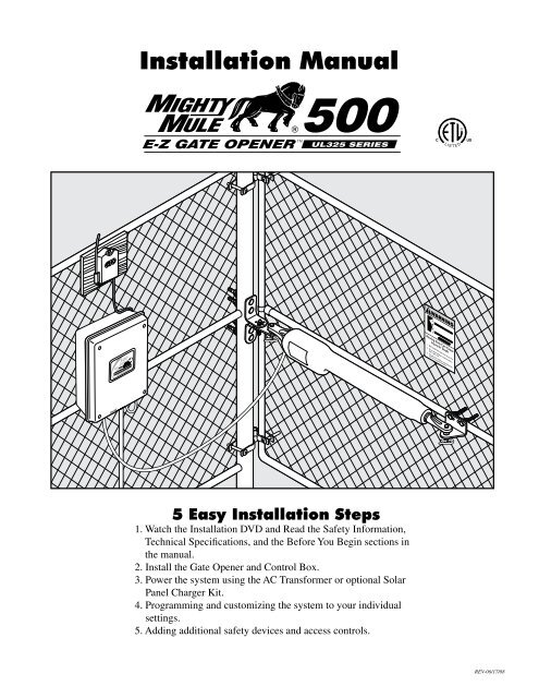
Before You BeginCheck Direction of Gate SwingYour PropertyPull-to-Open OptionInstructions begin onpage 13(Requires Push-To-Open Bracket#<strong>FM</strong>148—NOT INCLUDED)Your PropertyPush-to-Open OptionInstructions begin onpage 16Check Existing Gate Size and Material• Gate size: Up to 18 feet or up to 850 lbs—See charton page 9.• Type of gate material: Vinyl, aluminum, chain link,farm tube, wrought iron, wood (not recommended forsolid surface gates).IMPORTANT: Check for Proper Gate <strong>Installation</strong>For the <strong>Mighty</strong> <strong>Mule</strong>® to work properly, gate must be plumb, level, set in concrete, swing freely and not touch theground and have good working hinges.AFEBCA - LevelB - PlumbC - Free SwingingD - Secured Posts in ConcreteE - Centerline MountingF - Good Working Hinges (ballbearing hinges are recommendedon gates over 250 pounds)D10
Before You BeginColumn <strong>Installation</strong> InformationIF THIS OPENER WILL BE USED WITH GATES THAT ARE MOUNTED ON MASONRY, BRICK,OR ROCK (etc.) COLUMNS, READ THE FOLLOWING CAREFULLY BEFORE PROCEEDINGA. The simplest solution is to install the opener in apush-to-open configuration (requires push-to-openbracket, see accessory catalog). The minimumclearance is easier to achieve and clearance is nolonger a problem, since the opener will be pushingthe gate away from the column instead of pullingit toward the column. It is recommended thatyou place a steel plate between the opener mountingbrackets and masonry surface for additionalstrength.Pivot BracketColumnAB!WARNINGB. If a push-to-open installation is impossible due totraffic hazards, terrain, etc., another option is tore-hang the gate. You may hang it on a post, eitherin the center of the column or at the back corner, ormove the gate to the back corner of the columns.C. The most difficult solution is to cut a notch in thecolumn to accommodate the opener and powercable. This job is NOT for the inexperienced!Column Mount Example(A + B can not exceed 14 inches)Example: If A is 2" then B can not exceed 12"GateMoving Gate Can CauseInjury Or Death1. KEEP CLEAR! Gate may move at any time.2. Do not allow children to operate gate orplay in gate area.3. This gate is for vehicles only. Pedestriansmust use a separate entrance.HingeItems IncludedInsta lation Overview for the. .BOperatorArmCTransformerInsta lation Overview for the .D!<strong>Installation</strong>VideoWARNINGEMoving Gate Can CauseInjury Or Death1. KEEP CLEAR! Gate may move at any time.WarningSign2. Do not allow children to operate gate orplay in gate area.3. This gate is for vehicles only. Pedestriansmust use a separate entrance.FGate BracketJClosed PositionBracketAReceiver andControl BoxHPost Pivot BracketIPost BracketsRB<strong>500</strong>12 Volt / 7.0 Amp MountBatteryGKTransmitterLPTV8” Nylon Cable Tie (14)3/8” x 8” Bolt (4)3/8” x 3” Bolt (2)3/8” x 2” Bolt (1)UW5/16” x 1-3/4” Bolt (1)MNO3/8” Bushing (2) 5/16” Lock Washer (1) 5/16” Washer (1)QRSHairpin Clip (2) 3/8” Lock Washer (7) 3/8” Washer (9)X Y Z2” Mounting Screw (5) 3/8” x 1-1/4” Clevis Pin (2) 3/8” Nut (7) 5/16” Nut (1)11
Before You BeginTools NeededDrill3/8” Bit5/16” BitPenCenterPunchPliersHack Saw 1/2”wrenchHammerFlat HeadScrewdriverLevelClampx29/16”wrenchAdjustableWrenchPhilips HeadScrewdriverWireStripperSmallFlat HeadTapeMeasureItems Not Included• Low voltage wire will be needed to run from thetransformer to the control box; length dependsupon the distance between the transformer powersupply and the control box. See Transformer Wiring<strong>Installation</strong> on page 20, and the accessory catalog.• PVC conduit.• If your gate is more than 1000' away from an acpower source you will need to use at least one<strong>Mighty</strong> <strong>Mule</strong>® 5 watt solar panel to trickle chargethe battery. See the accessory catalog (Do not useboth transformer and solar).• If you have thin walled tube or panel gates, seeRecommended Reinforcement Examples in “QuickReference Guide” after Step 3 of “Mounting Openerto Gate” section.• Depending on the type of gate, a horizontal crossmember or mounting plate may be needed to mountthe front of the opener and gate bracket to the gate.See Gate Bracket Mounting Examples in “QuickReference Guide” after Step 3 of “Mounting Openerto Gate” section.• Surge protection for transformer.• Some types of installations require u-bolts.• If the gate is a push-to-open refer to page 16 in<strong>Installation</strong> <strong>Manual</strong>.• Additional washers or a metal plate may be neededfor wooden post.• Outlet in weatherproof cover.• Strain relief nuts for accessory devices.• If post is more than 6”, bolts longer than 8” areneeded.12
Your PropertyGate Opener <strong>Installation</strong>Mounting Pull-to-Open Opener to Gate12XVMBQIHXIRSMYQFAssemble post bracket parts.3Attach opener to gate bracket and secure with requiredhardware.Reinforcement and Gate Bracket MountingSteel Pipe Cut in Half(not supplied)GateBracketGateBracketThin WalledTube GateWood or MetalReinforcement(not supplied)FRONT VIEWSIDE VIEWPanelGateGateBracket1” x 6” Wood ReinforcementMounting PlateCreated forDecorative Gate(required but notsupplied)Remove excess bolt lengthwith hacksaw or bolt cuttersWith Gate in OPEN position, using clamps, secure opener togate post and center cross member of gate.Recommended reinforcement and gate bracket mountingexamples.452" Min. - Pinch-Point ClearanceTop View12" Min.2Remove clevis pin from the gate bracket and support looseopener.Swing gate to CLOSED position-check clearance/binding by inspectingalignment. TIP: Turning the pivot bracket over gives more holealignment options for the post pivot bracket assembly.13
Your Property6Gate Opener <strong>Installation</strong>Mounting Pull-to-Open Opener to Gate72U1OZNOPEN gate and re-attach opener with clevis pin. Check for level.Clamp securely.8Secure post pivot bracket to post bracket when clearance is OK(Step 5) in both open and closed positions.9Mark middle of post bracket slots on fence post. Mark middle ofgate bracket slots on gate cross support.Remove clamps, post, gate brackets, and opener. Then use ahammer and center punch to mark hole positions.1011YRSPDrill holes completely through gate post and gate cross support.14Attach post bracket assembly to fence post. NOTE: Must bethrough bolted.
Your Property6Push-to-Open <strong>Installation</strong>Mounting Push-to-Open Opener to Gate7U1OZNCLOSE gate and re-attach opener with clevis pin. Checkfor level. Clamp securely.8Secure post pivot bracket to post bracket when clearance is OK(Step 5) in both open and closed positions.9Mark middle of post bracket slots on fence post. Mark middle ofgate bracket slots on gate cross support.Remove clamps, post, gate brackets, and opener. Then use ahammer and center punch to mark hole positions.1011SRYPDrill holes completely through gate post and gate cross support.17Attach post bracket assembly to fence post. NOTE: Must bethrough bolted.
Your Property12Push-to-Open <strong>Installation</strong>Mounting Push-to-Open Opener to Gate13SRYTAttach gate bracket assembly to gate cross support.Attach and secure opener assembly to brackets.14 15Check for level. Adjust post bracket if necessary.Remove bolt excess length on post and gate bracket withhacksaw.18
Control Box <strong>Installation</strong>Control Box <strong>Installation</strong>7GRNWHTBLUBRNORGREDBLKMASTER CABLEGTO RCVR.GRNWHTBLUBRNORGREDBLKGRNWHTBLUBRNORGREDBLKCOMCOMCYCLESAFETYEXITSHADOWCLOSEEDGEOPENEDGEGRNBLKREDInsert 7 wires into corresponding color terminals.ALM1 2 3 4 5 6 7AUXRLY MASTER CABLESLAVE CABLE CONTROL INPUTSRECEIVERPWR INCHARGINGLEARNSLV LIMITS48GRNWHTBLUBRNORGREDBLKCorrect COMWrong WrongCOMCYCLESAFETYSecure wires in terminals.MASTER CABLE CONTROL INPUTSIf u s i n g o p t i o n a l s o l a r p a n e l c h a r g e r i n s t e a d o f t r a n s f o r m e r, g o to p a g e 23.IMPORTANT: Do n o t c o n n e c t b o t h s o l a r p a n e l a n d t r a n s f o r m e r.Transformer Wiring <strong>Installation</strong>9Top View10Min 3 FtMax 1,000 FtGTO TransformerMounts HereCAUTION: Pleasecall your power companybefore you dig. Failure todo so could cause injuryor even death.Locate power outlet and identify wire path to control box.NOTE: If OUTLET is OUTSIDE use weatherproof cover.Dig trench and lay wire from AC power source to control box.Use only 16 guage multi-stranded, low voltage, PVC sheathedwire (RB509). NOTE: DO NOT use telephone wire or solid corewire. NEVER splice wires together. We recommend running wirein PVC conduit.20
SLAVE CABLE MASTER CABLECONTROL INPUTSON11Control Box <strong>Installation</strong>Transformer Wiring <strong>Installation</strong>123C1 12Use PVC conduit from ground up to control box.Cut excess cable/strip 1/2” off 2 wires/twist ends. Attach wiresto transformer screw terminals.13POWERINPUTSGTO14FUSE15CONTROLINPUTSLOCK AUXRLYBATT+BATT-POWERINPUTSGTO 18VOLTTRANSFORMEROR SOLARCONTROLOUTPUTSLOCKPWRAUXRLY10”GTO RCVR.RECEIVERCYCLESAFETYSHADOWCLOSEEDGEOPENEDGEGRNBLKREDALMCONTROL INPUTSRECEIVERS4LEARNSLV LIMITMAXONONPUSHSIMULT.ONONS2LEARNMAST LIMITS3LEARN RMTSTATUSSTALL FORCEGTO 18VOLTTRANSFORMEROR SOLARPOWERINPUTSLOCKPWRAUXRLYCONTROLOUTPUTSGRNWHTBLUBRNORGREDBLKGRNWHTBLUBRNORGRED1 2 3 4 5 6 7SLAVE CABLEMASTER CABLEPWR INCHARGINGBLKBLKFeed other end of low voltage wire 10” into box throughthe hole.COMInsert one wire into each 18VAC terminal. Colors do not matter.15GTO 18VOLTTRANSFORMEROR SOLARPOWERINPUTS16GRNSecure with terminal screws.WHTCorrect Wrong WrongBLUBRNORGREDBLKGRN1 2 3 4 5 6 7LOCKPWRAUXRLYSLAVE CABLECONTROLOUTPUTS21Plug in transformer to power outlet. (Use of a surge protector ishighly recommended. If outdoors use weatherproof box.)
Control Box <strong>Installation</strong>Receiver <strong>Installation</strong>FCC Regulation1This device complies with FCC rules Part 15.Operation is subject to the following conditions:1. This device may not cause harmful interference.2. This device must accept an interference thatmay cause undesired operation.Transmitter distance may vary due to circumstancesbeyond our control. NOTE: The manufacturer isnot responsible for any radio or TV interferencecaused by unauthorized modifications tothis equipment. Such modifications couldvoid the user’s authority to operatethe equipment.210’MaxInstall Receiver within 10 ft of control box (longer lengths available- call us). NOTE: NEVER splice receiver cable. DO NOTrun cable through metal conduit because the receiver signalrange will decrease. DO NOT run cable through conduit containingAC wire. DO NOT place receiver within 3 feet of AC power.WWTips1. Mount the receiver high and above any obstructions; fencepickets, column caps, etc.2. If radio control seems limited try moving the receiver 1-2 feetin each direction to reduce radio noise “dead spots”.Check Receiver/Remote signal reception in mounted position/OK—secure Receiver in position to fence or post. NOTE: If mountingon metal fence, mount receiver on a piece of wood. Mounting thereceiver on metal can cause intereference and the receiver may notwork properly. DO NOT mount upside down.Gate Stop <strong>Installation</strong>1J21 12Fully open gate. Attach gate stop with one of the following:• U-bolts—tube and chain link gates (Not included)• Wood/lag screws—flat aluminum/wood supports (Not included).Do not tighten.22Position gate stop with gate CLOSED to fence post. Tightenfasteners. Cut off excess bolt length.
Solar Panel <strong>Installation</strong>(Optional)The table and map illustrate themaximum number of gate cycles toexpect per day in a particular areawhen using from 5 to 30 watts ofsolar charging power. (see accessorypages in back of this book). Thefigures shown are for winter(minimum sunlight) and do not account for the use ofany accessory items. Accessories connected to yoursystem will draw additional power from the battery.Winter Ratings Zone 1 Zone 2 Zone 312 v single gate ( 5 watts) solar charger 4 8 1312 v single gate (10 watts) solar charger 8 16 2612 v single gate (15 watts) solar charger 11 20 3012 v single gate (20 watts) solar charger 14 28 3812 v single gate (25 watts) solar charger 17 36 4612 v single gate (30 watts) solar charger 20 44 54NOTE: A minimum of 5 watts of solar charging poweris required for <strong>Mighty</strong> <strong>Mule</strong> <strong>500</strong> single gate systems, witha maximum of 30 watts. A second battery (7 amp tractor,auto or deep cycle marine battery) is recommended for solarand/or high traffic applications, if needed. ConsultSolar Panel <strong>Installation</strong> Instructions for further information.12TowardEquatorThe solar panel must be positioned facing the path of the sunand in an open area away from shade. It should receive at least 8hours of direct sunlight for a full charge.Feed wire from solar panel through hole in knockout incontrol box.IMPORTANT: Mount the panel usingthe curved pipe provided to maintainthe proper angle to the sun.IMPORTANT: Requires 8 hoursof direct sunlight a day.23
SLAVE CABLE MASTER CABLECONTROL INPUTSONSolar Panel <strong>Installation</strong>32POWERINPUTSGTO4FUSE15CONTROLINPUTSLOCK AUXRLYPOWERINPUTSGTO 18VOLTTRANSFORMEROR SOLARBATT+BATT-CONTROLOUTPUTSLOCKPWRAUXRLY10”GTO RCVR.RECEIVER1S4LEARNSLV LIMITMAXONONPUSHSIMULT.ONONS2LEARNMAST LIMITS3LEARN RMTSTATUSSTALL FORCEGTO 18VOLTTRANSFORMEROR SOLARPOWERINPUTSGRNWHTBLUBRNORGREDBLKGRN1 2 3 4 5 6 7SLAVE CABLEPWR INCHARGINGRECEIVERLOCKPWRAUXRLYCONTROLOUTPUTSWHTBLUBRNORGREDBLKBLKMASTER CABLEFeed cable 10” into box.5GTO 18VOLTTRANSFORMEROR SOLARPOWERINPUTSInsert RED wire into SOLAR (+) positive terminal andBLACK wire into SOLAR (-) negative terminal.CONTROLOUTPUTSLOCKPWRAUXRLYGRNCorrect Wrong WrongWHTGRN WHT BLUE BRNBLUBRNORGSecure with terminal screws.1 2 3 4 5SLAVE CABLEMultiple Panel <strong>Installation</strong>sNOTE: All connections should beweatherproofed using weatherproofsplice kits available at hardware andelectrical supply stores.Solar Panels connect in PARALLELREDBLACKREDBLACKattach BLACK to negative (–) solar terminal on control boardattach RED to positive (+) solar terminal on control board24
Control Box SettingsDIP SwitchesIMPORTANT: Before making any changes to dip switches turn control box off!DIP#1ON**___Soft start enabled (factory preset).OFF __Soft start disabled.15DIP#2ON**___Buzzer warning enabled (factory preset).OFF __ Buzzer warning disabled.1 2 3 4ON1 2 3 4DIP#3ON*___Push-to-open.OFF*__Pull-to-open (factory preset).DIP#4ON*___Slave opens simultaneously with master.OFF*__Slave opens after master. (factory preset).NOTE: Not applicable for single gate operator.*factorypresets shownDIP Switch #1 - Soft Start/StopThe soft start/stop feature slowly starts the gate as itbegins to open or close and slows the gate as it comesto the opened or closed position. This saves wear andtear on the gate and gate opener system.DIP Switch #4 - Delay/Simultaneous operationIf set to ON the slave opens simultaneously with themaster. If set to OFF the slave opens after the master.NOTE: Not applicable for single gate operator.DIP Switch #2 - Warning BuzzerThe warning buzzer alerts you when the gate openeris beginning to either open or close the gate. It soundsfor the first 2 seconds in each direction. It also soundsa warning when the gate obstructs two times in onecycle. Switching this to OFF only disables the openand close warning not the obstruction warning.DIP Switch #3 - Push/Pull-to-OpenIf your gate opens into the property the DIP Switch isset to the OFF position (factory setting). If your gateopens out from the property the DIP Switch must beset to the ON position. NOTE: if you have a Push-to-Open gate application you will need a Push-to-Openbracket (see Push-to-Open Instructions on page 16).25
15Control Box SettingsSetting Pull-to-Open (Closed) Gate Limit (for push-to-open go to pg. 16)12215ON13With gate in OPEN position, turn control box power ON.Press button on opener remote; gate should start closing. Press buttonon opener remote again when gate is in desired CLOSED position.3 415OFFSOFT START OFFWARNING OFFOPEN PULLSLV OPEN DLY.MODE1 OF<strong>FM</strong>ODE2 OFF120 MIN MAX1 2 3 4ONONONPUSHSIMULT.ONONS3LEARNMAST LIMITS2LEARNSLV LIMITS412Press and hold the “ LEARN MAST LIMIT” button for 5 seconds,or until the alarm sounds.NOTE: If your gate obstructs before it fully closes, you mayneed to increase the stall force. (See page 28)Resetting Closed Gate LimitPress button on opener remote to fully open gate. Closed limit isset upon reaching fully open position. Test and, if needed, resetand start over.562LEARN RMTOFF120 MIN MAXS3SOFT START OFFONWARNING OFFONOPEN PULLPUSH LEARNSLV OPEN DLY.SIMULT. MAST LIMITMODE1 OFFONS2MODE2 OFFON1 2 3 4ON1Press button on opener remote to open gate.26LEARNSLV LIMITPress and hold the “LEARN MAST LIMIT” button for10 seconds, or until the alarm sounds to clear. Go back to thesetting closed limit steps on the top of this page.S4
GRNWHTBLUBRNORGREDBLKGRNWHTBLUBRNORGREDBLKCOMCOMCYCLESAFETYEXITSHADOWCLOSEEDGEOPENEDGEGRNBLKREDS4S21 2 3 4ONGRNGRNWHTWHTBLUBLUBRNBRNORGORGREDREDBLKBLKGRNGRNWHTWHTBLUBLUBRNBRN ORGORG REDREDBLKBLKCOMCOMCYCLE COMCYCLE SAFETYSAFETY EXITSHADOW EXITCLOSESHADOW EDGECLOSE OPENEDGEOPEN GRNEDGEBLKGRNREDBLKREDS3S4S4ONONONONS2S21 2 3 4ON1 2 3 4ONONONONONS3OFFS3OFF1 2 3 4Control Box SettingsSetting Push-to-Open (Open) Gate Limit (for pull-to-open go to pg. 26)1POWERINPUTSLOCKPWRAUXRLYCONTROLOUTPUTS2GTO RCVR.ALM1 2 3 4 5 6 7SLAVE CABLE MASTER CABLECONTROL INPUTSRECEIVERCHARGINGPWR INLEARNSLV LIMITLEARNMAST LIMITBATT-OFFSOFT START OFFWARNING OFFOPEN PULLSLV OPEN DLY.MODE1 OF<strong>FM</strong>ODE2 OFFONONPUSHSIMULT.ONON120 MIN MAXLEARN RMTFUSE15BATT+STATUSAUTO CLOSE TIME STALL FORCE23ONWith gate in CLOSED position, turn control box power switchto ON.31Press button on opener remote; gate should start opening. Press buttonon opener remote again when gate is in desired OPEN position.4POWERINPUTSGTOTRANSF LOCKPWRPOWERINPUTSCONTROLINPUTS OUTPUTSLOCKPWRAUXRLY18 VACorSOLARGTOLOCKAUXONLEARN RMTMAXS3ONONPUSH LEARNSIMULT. MAST LIMITONS2ONLEARNSLV LIMITS4GTO GTO RCVR. RCVR.ALMALM1 1 2 2 3 3 4 4 5 5 6 6 7 7RECEIVER RECEIVERSLAVE CABLE MASTER CABLE CABLECONTROL CONTROL INPUTS INPUTSLEARNSLV LIMITLEARNSLV LIMITBATT-BATT-LEARN RMTLEARN RMT120 MIN MAX120 MIN MAXSOFT START OFFSOFT WARNING START OFF OFFWARNING OPEN OFF PULLPUSH LEARNOPEN PULLPUSH LEARNSLV OPEN DLY.SIMULT. MAST LIMITSLV OPEN DLY.SIMULT. MAST LIMITMODE1 OF<strong>FM</strong>ODE1 OF<strong>FM</strong>ODE2 OF<strong>FM</strong>ODE2 OFFFUSEFUSE1515BATT+BATT+AUTO CLOSE TIME STALL FORCEAUTO CLOSE TIME STALL FORCESTATUSSTATUS12Press and hold the “LEARN MASTER LIMIT” button for 5seconds, or until the alrm sounds.NOTE: If your gate obstructs before it fully closes, you mayneed to increase the stall force. (See page 28)Resetting Open Gate LimitPress button on opener remote to fully close gate. Open limit isset upon reaching the fully closed limit. Test and, if needed resetand start over.563POWERINPUTSGTOCONTROLINPUTSLOCK AUXRLY2ONMAXONONPUSHSIMULT.LEARN RMTS3LEARNMAST LIMITSLAVE CABLE MASTER CABLECONTROL INPUTSBATT-FUSE15BATT+ONONS2GTO RCVR.RECEIVER1LEARNSLV LIMITS4Press button on opener remote to close gate.27Hold the “LEARN MASTER LIMIT” button for 10 seconds,or until the alarm sounds to clear. Go back to setting open gatelimit step 1 at the top of this page.
Control Box SettingsSetting Obstruction Stall Force115MODE1 OF<strong>FM</strong>ODE2 OFFONONSOFT START OFFWARNING OFFOPEN PULLSLV OPEN DLY.1 2 3 4ONONONPUSHSIMULT.120 MIN MAXAUTO CLOSE TIME STALL FORCEIMPORTANT: For safety reasons theobstructions setting or Stall Force onthe <strong>Mighty</strong> <strong>Mule</strong>® control board comesfrom the factory set at MIN (minimum).In many installations this setting willneed to be adjusted to overcome theweight and size of the gates.ALWAYS KEEP SAFETY AT THE TOP OFYOUR LIST WHEN ADJUSTING ORSERVICING YOUR AUTOMATICGATE OPENERLEARNSLV LIMITLEARNMAST LIMITTurn the “STALL FORCE” arrow in the center of the potentiometer withsmall flat head screwdriver. Adjust the sensitivity from the MINIMUMposition up to the point where the gate operates without obstructing from itsown weight or the wind conditions in your area.LEARN RMTSTATUSSetting Personal Transmitter CodeAll GTO transmitters are set to a standard code at the factory and are ready to operate your GTO PRO® Gate Opener ® .For your safety and security, however, we strongly recommend that you replace the factory setting with your own personal code.Follow the directions below:121 2 3 4 5 6 7 8 9Remove back cover of the opener remote.Flip opener remote over. Use small screwdriver to move switchesto random positions. If you have more than one transmitter,now is a good time to set them all with the same code.28
Control Box SettingsSetting Personal Transmitter Code3415AUTO CLOSE TIMESTALL FORCESTATUSReplace and secure back cover of the opener remote.LEARN RMT120 MIN MAXSOFT START OFFONS3WARNING OFFONOPEN PULLPUSH LEARNSLV OPEN DLY.SIMULT. MAST LIMITMODE1 OFFONS2MODE2 OFFONGo to control box. Press and hold the remote and “LEARN RMT”buttons simultaneously for 5 seconds or until the alarm sounds.1 2 3 4ON561515AUTO CLOSE TIMESTALL FORCESTATUS1OFFSOFT START OFFWARNING OFFOPEN PULLSLV OPEN DLY.MODE1 OF<strong>FM</strong>ODE2 OFF120 MIN MAX1 2 3 4ONONONPUSHSIMULT.ONONLEARN RMTS3LEARNMAST LIMITRelease the remote button, then release the “LEARN RMT”button. The new code is now programmed. Fill in boxes belowwith your transmiter code for your records.S22Replace control box cover.Example1 2 3 4 5 6 7 8 9Fill In Code For Your Records1 2 3 4 5 6 7 8 9FCC RegulationThis device complies with FCC rules Part 15.Operation is subject to the following conditions:1. This device may not cause harmful interference.2. This device must accept an interference thatmay cause undesired operation.Transmitter distance may vary due to circumstancesbeyond our control. NOTE: The manufacturer isnot responsible for any radio or TV interferencecaused by unauthorized modifications tothis equipment. Such modifications couldvoid the user’s authority to operatethe equipment.29
Connecting Additional DevicesBefore You BeginAlthough GTO strongly recommends the use of additional safety devices, we do notendorse any specific brand names. Only use products that are certified and listed tobe in compliance with any applicable UL safety standards(Underwriters Laboratories) and national and regional safety codes.Call GTO Sales at 1-800-543-4283 for information on compatible products for yourspecific applicationPLEASE NOTE: Contact Sensors, Non-Contact Sensors, and Shadow Loops are not included with the <strong>Mighty</strong><strong>Mule</strong>® <strong>500</strong>. NOTE: Refer to the sensor manufacturer’s instructions for information about installing these deviceson a vehicular gate.The <strong>Mighty</strong> <strong>Mule</strong>® <strong>500</strong> will ONLY accept accessory devices with normally open dry contact output.30
Connecting Additional DevicesInput ConnectionsNOTE:GRN• All control inputs are dry-contact, normally open, inputs. DO NOT apply external voltage sources to these inputs.• All inputs are connected with respect to COMMON terminal.WHT• The status light will blink once when its corresponding input is activated.BLU1 COM: Circuit common (reference for all logic input)• Two (2) terminals to provide extra common connection point.2 CYCLE: (Typically for use with doorbell button or hardwired key pad)• Each activation at this input will cycle the operation as follows:….→ OPEN → STOP → CLOSE → STOP → OPEN → …3 SAFETY: (Typically for use with photo beam device, loop detectoror other non-contact sensors)• Activation of this input while the gate is closing will cause the gate tostop and return to the opened position.• Activation of this input while the gate is opening has no effect (gatewill continue to open).• Activation of this input while gate is idle will prevent gate from closing.4 EXIT: (Typically for use with exit loop or wand)• Activation of this input will open the gate if it’s not already at theopen position• Activation of this input while at open limit will restart the auto close time(if enabled).5 SHADOW: (Typically for use with loop detector device)• This input is only monitored when the gate is at the fully openposition. At any other position, activation of this input has no effect ongate operation.• Activation of this input while gate at the fully open position willprevent gate from closing.1234567GTO RCVR.ORGREDBLKBRNORGREDBLKCOMCOMCYCLESAFETYEXITSHADOWCLOSEEDGEOPENEDGEGRNBLKREDALM6 7BLE MASTER CABLECONTROL INPUTSRECEIVER6 CLOSE EDGE: (Typically for use with safety edge device)• Activation of this input while the gate is closing will cause the gate tostop and reverse direction for approximately 2 seconds.• Activation of this input while the gate is opening has no effect (gate will continue to open).• Activation of this input while gate is idle will prevent gate from closing.7 OPEN EDGE: (Typically for use with safety edge device)• Activation of this input while the gate is opening will cause the gate tostop and reverse direction for approximately 2 seconds.• Activation of this input while the gate is closing has no effect (gatewill continue to close).• Activation of this input while gate is idle will prevent gate from opening.31
Connecting Additional DevicesConnecting AccessoriesMASTER CABLECONTROL INPUTSRECEIVERGRNWHTBLUBRNORGREDBLKCOM1 2 3 4 5 6 7COMCYCLESAFETYEXITSHADOWCLOSEEDGEOPENEDGEGRNBLKREDGTO RCVR.ALM1345According toApplicationNOCOMNCV +V –LOOPLOOPGTO Loop Detector1 2 3 4 5 6 7 8 9 10ONDIP167According toApplicationEdge SensorLOOP12<strong>Mighty</strong> <strong>Mule</strong>Push Button Control1 2 ABC4GHI7PRS5JKL8TUV0<strong>Mighty</strong> <strong>Mule</strong> Keypad3 DEF6MNO9WXY1231GTO Photo Beams14<strong>Mighty</strong> <strong>Mule</strong>Vehicle SensorRefer to Vehicle Sensormanual for additionalconnections.NOTE: Connections are for typicalapplications. There may be additionalconnection options for applications thatare not illustrated here.32
Connecting Additional DevicesConnecting GTO Automatic LockGTO LOCKPOWERINPUTSCONTROLOUTPUTSLOCKPWRAUXRLYGTO 18VOLTTRANSFORMEROR SOLARWire fromAutomaticGTO LockGTO Lock:For use exclusively with GTO Lock (<strong>FM</strong>143 or <strong>FM</strong>144).Connecting other devices to these terminals may cause incorrectoperation and void your warranty. You do not use the lock boardwith this control board.GTO Lock Connection:Connect the red and black leads from the lock to the GTO LOCKterminal on the GTO/PRO® 2000XL control board.Connecting Other Auxiliary Devices (Mag Locks, Sirens, Lights. . .}• These 2 terminals are normally open 'dry-contact' (no voltage) relay ouput.• These 2 terminals are ON (shorted) whenever the gate is moving and OFF (opened) otherwise.• These 2 terminals maximum rating is 24Vdc, 1 Amp.Maintenance & Troubleshooting• On all gates weighing 250 lb. or more, routinelygrease the ball bearing hinges at least 4 times a year;more frequently if the gates are near a coastal area.• Keeping a few mothballs in the control box willdiscourage insects from entering it and damaging thecontrol board.Maintenance Tips• Clean the push-pull tube with a soft, dry cloth andapply silicone spray to it at least once per month.• While oxidation is a normal part of weatheringof equipment that is exposed to the elements, werecommend you apply silicone spray to the front andrear mounts to minimize this effect.33
Visual FeedbackSymptom Diagnosis Check:Status (clear)1 blinkStatus (clear)2 blinksStatus (clear)3 blinksStatus (clear)4 blinksStatus (clear)5 blinksStatus (clear)6 blinkRF (yellow) FlickersRF (yellow) OFFPower (green) ONPower (green) OFFCycle TerminalShortedSafety TerminalShortedExit TerminalShortedShadow TerminalShortedClose Edge TerminalShortedOpen Edge TerminalShortedReceiving 318 MHzRFNo 318 MHz RFReceivedAC or Solar PowerPresentNo AC or SolarPowerDisconnect the push button, keypad, intercom keypad, or any otheraccessory wired to this terminal. Try the remote. If the remote works, thenthe problem is the accessory.Disconnect the loop detector, photo beam, or any other accessory wiredto this terminal. Try the remote. If the remote works, the problem is theaccessory.Disconnect exit wand, loop detector, photo beam, Knox box, or any otheraccessory wired to this terminal. Try remote. If the remote works, theproblem is the accessory.Disconnect the loop detector, photo beam, or any other accessory wired tothis terminal. Try remote. If the remote works, the problem is the accessory.Disconnect the edge sensor, photo beam, or any other accessory wired to thisterminal. Try the remote. If the remote works, the problem is the accessory.Disconnect edge sensor, photo beam, or any other accessory wired to thisterminal. Try the remote. If the remote works, the problem is the accessory.Normal operation when remote or wireless keypad is used.• Battery in Remote• Program Remote• Antenna Receiver Connections• Antenna ReceiverNormal OperationTransformer:• Breaker or GFI• Power at AC outlet.• Output of Transformer.• Voltage on wire at 18 VAC InputSolar:• Solar Panel Wires Reversed• Weather• Solar Panel Placement• Output of Solar Panel• Voltage on wire at Solar InputCharge (red) ON Fast Charging Mode Battery Voltage should be ~14.8 VDC when connected to the circuit boardCharge (red) FastBlinkingCharge (red) SlowBlinkingCharge (red) OFFSoak Charging ModeFloat ChargeBattery Not BeingChargedBattery Voltage should be ~14.1 VDC when connected to the circuit boardBattery Voltage should be ~13.8 VDC when connected to the circuit board• AC power• Transformer• Solar Panel• Charging Circuit35
Repair ServiceIf your <strong>Mighty</strong> <strong>Mule</strong> ® Gate Opener is not operating properly, please follow the steps below:1. First use the procedures found in the Maintenance& Troubleshooting Guide (see page 33).2. If you are unable to solve the problem, call theGTO Service Department at (800) 543-1236, or(850) 575-4144. Refer to the serial number (locatedon the right hand side of the control box) and dateof purchase when calling for assistance.3. If repair or replacement of your gate opener isnecessary, the Service Department will assign aReturn Goods Authorization (RGA) number toyou to track return of equipment.4. Include a copy of your receipt and securely pack thecomponent(s) authorized for return to the factory.Write the RGA number issued to you on the outsideof the package in LARGE BOLD PRINT. Shipthe package(s) freight prepaid to: GTO, Inc., 3121Hartsfield Road, Tallahassee, Florida,USA 32303.NOTE: Products returned to GTO without a Return Goods Authorization (RGA) number inLARGE BOLD PRINT on the outside of the package WILL NOT be accepted. Items returnedto GTO freight collect WILL NOT be accepted. Items returned without proof of purchase willnot be repaired under warranty.The GTO, Inc. Technical Service Department is openMonday – Friday 8:00 A.M. – 7:00 P.M. (Eastern Time)Telephone (800) 543-1236Telephone (850) 575-4144Fax (850) 575-8950 • Web site: www.mightymule.comE-Mail: techsupport@gtoinc.com
Conversion ChartConverting Metric Units to English EquivalentsWhen You Know Multiply By To Find Symbolcentimeters 0.3937 inches in. (or ")meters 3.2808 feet ft. (or ')kilograms 2.2046 pounds lb. (or #)Converting English Units to Metric EquivalentsWhen You Know Multiply By To Find Symbolinches 2.5400 centimeters cmfeet 0.3048 meters mpounds 0.4535 kilograms kgConverting Temperaturedeg. Celsius (ºC x 1.8) + 32 deg. Fahrenheit ºFdeg. Fahrenheit (ºF-32) ÷ 1.8 deg. Celsius ºCFor Your RecordsPlease record the product serial number (located on the right hand side of the control box), and the date and placeof purchase in the spaces provided below. Refer to this information when calling GTO for service or assistancewith your automatic gate opener.Serial Number ____________________ Date of Purchase ____________________Place of Purchase ____________________Remember to keep all receipts for proof of purchase.37
®E-Z GATE OPENERSACCESSORIESAccessories are Available From Your Retail StoreSolar Panel (<strong>FM</strong>121)The Solar Panel is a 5 watt solar powered battery charger for use with the <strong>FM</strong><strong>500</strong> & <strong>FM</strong>502 gateoperator systems. Particularly suited for remote installations, each Solar Panel comes with tubularsteel support, mounting clips, wire connectors, and 8 ft. of low voltage wire (see Low Voltage Wirefor additional wire). The <strong>Mighty</strong> <strong>Mule</strong>® control board has clearly labeled terminal connections foreasy installation of the Solar Panel. <strong>Installation</strong> in some regions of the world will require multiplesolar panels for adequate charging power. Dual gates require a minimum of 10 watts of solar chargingpower. (10 watt solar panels are available)Push Button Control (<strong>FM</strong>132)Unlit doorbell button for remote entry or exit control. Wires directly to the control board and uses 16gauge multi-stranded, dual conductor low voltage wire (sold separately).Pin Lock (<strong>FM</strong>133)The Pin Lock substitutes for the clevis pin at the front end of the <strong>Mighty</strong> <strong>Mule</strong>® gate openers. Helpsprevent theft of the operator from the gate, while allowing quick release of the operator.Key Chain Two Button Transmitter (<strong>FM</strong>134)The Key Chain Mini Transmitter is a miniature version of the <strong>Mighty</strong> <strong>Mule</strong>® entry transmitter andhas the same adjustable code settings. (battery is included)Single Button Transmitter (<strong>FM</strong>135)The <strong>Mighty</strong> <strong>Mule</strong>® entry transmitter, with adjustable code settings, is standard equipment with all<strong>Mighty</strong> <strong>Mule</strong>® systems. (battery is included)1 2 34 5 67 8 90Digital Keypad (<strong>FM</strong>137)The specially designed digital keypad can be easily installed as a wireless or wired keypad. It can beprogrammed to use up to 25 different personal identification number (PIN) codes. Each code is faceprogrammable with additional security features built in. Wired installations require 16 gauge, lowvoltage, multi-stranded, dual conductor, direct burial wire (sold separately). Requires 3 AA batteries(not included).Mounting Post (<strong>FM</strong>100) - In GroundThis black powder coated pedestal is designed to provide convenient access to your keypad, wirelessintercom, or other access control device from your vehicle. With its break down design it is easy toinstall and works well in most standard applications. Surface Mount Flanges (F102) and Extensions(F103) for added height are available.<strong>Mighty</strong> <strong>Mule</strong>® Vehicle Sensor (<strong>FM</strong>138)The Gate Opening Sensor is designed for residential and agricultural applications and is compatiblewith most <strong>Mighty</strong> <strong>Mule</strong>® automatic gate opener models (see Sensor Box for model compatibility).The Sensor is an electromagnetic sensor, which offers 'hands free' operation of the <strong>Mighty</strong> <strong>Mule</strong>®Gate Operator with a 12 ft. radius of detection of vehicles in motion.AUTOMATICGATE LOCKAutomatic Gate Lock Pull-to-Open (<strong>FM</strong>143)A MUST for added security. Solenoid driven, with a steel housing. Unlocks and locks automaticallyas gates open and close. Used with <strong>Mighty</strong> <strong>Mule</strong>® DC swing gate operating systems for maximumstability and security. Comes with a keyed manual release. Recommended for gates over 8 ft. long.Ideal for animal enclosures or high wind areas.38
Accessories are Available From Your Retail Store (con't)Wireless Entry Intercom / Keypad (<strong>FM</strong>136)Allows owner to screen guest at the gate before allowing access to the property. Keypad also allows ownerto give up to 25 programmable entry codes to family, friends or approved delivery personnel. Codes can bepermanent of temporary. Up to <strong>500</strong> feet reception.Additional base stations available (F3101MBC).Replacement Battery (<strong>FM</strong>150)Standard 12 volt, 7.0 amp-hour, maintenance-free battery for the <strong>Mighty</strong> <strong>Mule</strong>® <strong>FM</strong><strong>500</strong> & <strong>FM</strong>502 gateoperator systems. This is the only battery approved for use with the <strong>Mighty</strong> <strong>Mule</strong>® <strong>FM</strong><strong>500</strong> & <strong>FM</strong>502 gateoperator systems. Life expectancy is 2-3 years.Low Voltage Wire (RB509)The 16 gauge, multi-stranded, dual conductor Low Voltage Wire is for connecting the AC poweredtransformer, or the Solar Panel to the control board. Also used for the connection of accessories, such as locks,keypads, push buttons and other wired control devices. This specially designed wire is UV treated, PVC coatedand ready for direct burial. Available in 1000' rolls or special lengths.Push to Open Bracket (<strong>FM</strong>148)Required when <strong>Mighty</strong> <strong>Mule</strong>® <strong>500</strong>/502 gate operator(s) must push the gate open, such as on a sloping driveway orwhere space prevents gate(s) from opening inward (pulled open). Order two PTO brackets for conversion of a dualswing gate installation.Column Mount Lock Receiver (433IH)For mounting the Automatic Gate Lock on brick columns, walls, or for other applications with limited spacebetween gate and post.Replacement Transformer (RB570)Standard 18 volt, 2200 mA, AC transformer for maintaining the battery included with the <strong>Mighty</strong> <strong>Mule</strong>® gateoperator. This is the only transformer approved for use with all UL325 <strong>Mighty</strong> <strong>Mule</strong>® gate operator systems.Garage Door Receiver (RB709U)The Garage Door Receiver allows you to use the same <strong>Mighty</strong> <strong>Mule</strong>® entry transmitter to operate your gate operatorand your garage door operator. Compatible with most garage door operators.If you have a question about any special order item,just call 1-800-543-GATE!The contents of all material available on this installation manual are copyrighted by GTO, Inc. (“GTO”), unless otherwise indicated. All rights are reserved by GTO, and content may not be reproduced,downloaded, disseminated, published, or transferred in any form or by any means, except with the prior, written permission of GTO. Any reprinting of GTO publications is by permission only. Copyrightinfringement is a violation of federal law.<strong>Mighty</strong> <strong>Mule</strong>¨, E-Z Gate¨, GTO¨, are registered trademarks of GTO, Inc. America’s DIY Automatic Gate Openers is a trademark of GTO, Inc. and are the exclusive property of GTO, Inc. (“GTO”).All rights are reserved by GTO, and these marks may not be used, in any for without the prior, written permission of GTO.39
®E-Z GATE OPENERSFor sales call toll free:1-800-543-GATE (4283)The GTO, Inc. Sales Department is openMonday – Friday 8:00 A.M. – 5:00 P.M. (Eastern Time)For technical service Call toll free:1-800-543-1236The GTO, Inc. Technical Service Department is openMonday – Friday 8:00 A.M. – 7:00 P.M. (Eastern Time)3121 Hartsfield Road • Tallahassee, Florida, USA 32303Telephone GTO Sales: 1-800-543-GATE (4283) or (850) 575-0176 • Fax (850) 575-8912or GTO Technical Service: 1-800-543-1236 or (850) 575-4144 • Fax (850)575-8950www.mightymule.com