AXNET Browser Interface Screen Shots and Descriptions ... - Linear
AXNET Browser Interface Screen Shots and Descriptions ... - Linear
AXNET Browser Interface Screen Shots and Descriptions ... - Linear

You also want an ePaper? Increase the reach of your titles
YUMPU automatically turns print PDFs into web optimized ePapers that Google loves.
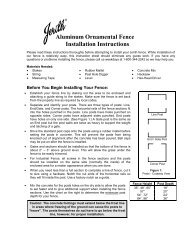
<strong>AXNET</strong>Access Controller<strong>Browser</strong> <strong>Interface</strong>& PC Utility SoftwareInstallation <strong>and</strong>User’s GuideCompatible withAccess Controllers:AM3PlusAE1000PlusAE2000Plus(760) 438-7000USA & Canada (800) 421-1587 & (800) 392-0123Toll Free FAX (800) 468-1340www.linearcorp.com
Table of Contents1 INTRODUCTION . . . . . . . . . . . . . . . . . . . . . . . . . . . . . . . . . . . . . . . . . 12 SYSTEM REQUIREMENTS . . . . . . . . . . . . . . . . . . . . . . . . . . . . . . . . 13 SUMMARY OF <strong>AXNET</strong> FEATURES . . . . . . . . . . . . . . . . . . . . . . . . . . 24 ACCESS CONTROLLER SETUPFOR <strong>AXNET</strong> MODE OF OPERATION . . . . . . . . . . . . . . . . . . . . . . . . 35 INSTALLING THE <strong>AXNET</strong> PC UTILITY SOFTWARE . . . . . . . . . . . . . 46 CONFIGURING A WINDOWS XP DIRECT SERIAL PPPCONNECTION FOR <strong>AXNET</strong> . . . . . . . . . . . . . . . . . . . . . . . . . . . . . . . 57 CONFIGURING A WINDOWS 2000 DIRECT SERIAL PPPCONNECTION FOR <strong>AXNET</strong> . . . . . . . . . . . . . . . . . . . . . . . . . . . . . . 108 CONFIGURING A WINDOWS XP MODEM PPP CONNECTION FOR<strong>AXNET</strong> . . . . . . . . . . . . . . . . . . . . . . . . . . . . . . . . . . . . . . . . . . . . . . . 159 ADDING A WINDOWS XP SHORTCUT ICON FOR THE PPPCONNECTION . . . . . . . . . . . . . . . . . . . . . . . . . . . . . . . . . . . . . . . . . 1710 CONFIGURING A WINDOWS 2000 MODEM PPP CONNECTIONFOR <strong>AXNET</strong> . . . . . . . . . . . . . . . . . . . . . . . . . . . . . . . . . . . . . . . . . . . 1811 ADDING A WINDOWS 2000 SHORTCUT ICON FOR THE PPPCONNECTION . . . . . . . . . . . . . . . . . . . . . . . . . . . . . . . . . . . . . . . . . 2112 INITIATING AN <strong>AXNET</strong> BROWSER INTERFACE SESSION . . . . . . 2113 NETWORK INSTALLATION BASICS . . . . . . . . . . . . . . . . . . . . . . . . 2214 NETWORKED INSTALLATION MAINTENANCE . . . . . . . . . . . . . . . 2315 NETWORK TROUBLESHOOTING . . . . . . . . . . . . . . . . . . . . . . . . . . 2316 <strong>AXNET</strong> PC UTILITY SOFTWARE BASICS . . . . . . . . . . . . . . . . . . . 2416.1 LAUNCHING THE <strong>AXNET</strong> PC UTILITY SOFTWARE . . . . . . 2416.2 TOOLS . . . . . . . . . . . . . . . . . . . . . . . . . . . . . . . . . . . . . . . . . . 2416.2.1 BACKUP/RESTORE . . . . . . . . . . . . . . . . . . . . . . . . . . 2416.2.2 FIRMWARE UPDATE . . . . . . . . . . . . . . . . . . . . . . . . . 2616.2.3 PREFERENCES . . . . . . . . . . . . . . . . . . . . . . . . . . . . . 2616.2.4 DOWNLOAD EVENTLOG. . . . . . . . . . . . . . . . . . . . . . 2716.3 EVENTLOG REPORTS . . . . . . . . . . . . . . . . . . . . . . . . . . . . . 2717 <strong>AXNET</strong> BROWSER INTERFACE NAVIGATION TREE . . . . . . . . . . . 2818 <strong>AXNET</strong> BROWSER INTERFACE SCREEN SHOTS ANDDESCRIPTIONS . . . . . . . . . . . . . . . . . . . . . . . . . . . . . . . . . . . . . . . . 2918.1 MAIN SCREEN . . . . . . . . . . . . . . . . . . . . . . . . . . . . . . . . . . . 2918.2 CARDHOLDERS> CARDHOLDERS SCREEN . . . . . 2918.3 CARDHOLDERS> ADD CARDHOLDERS SCREEN . 2918.3.1 DIRECTORY CODES . . . . . . . . . . . . . . . . . . . . . . . . . 3018.3.2 ENTRY CODES . . . . . . . . . . . . . . . . . . . . . . . . . . . . . 3018.3.3 BLOCK TRANSMITTERS . . . . . . . . . . . . . . . . . . . . . . 3118.3.4 SINGLE TRANSMITTERS . . . . . . . . . . . . . . . . . . . . . 3118.3.5 BLOCK CARDS . . . . . . . . . . . . . . . . . . . . . . . . . . . . . 3118.3.6 SINGLE CARDS . . . . . . . . . . . . . . . . . . . . . . . . . . . . . 3118.4 CARDHOLDERS> CARDHOLDER SETS SCREEN . . . . . . . 3218.5 CARDHOLDERS> BATCH ENTRY SCREEN . . . . . . . . . . . . 3318.6 EVENTLOG SCREEN . . . . . . . . . . . . . . . . . . . . . . . . . . . . . . 3418.7 BACKUP/DOWNLOAD SCREEN . . . . . . . . . . . . . . . . . . . . . 3418.7.1 BACKUP . . . . . . . . . . . . . . . . . . . . . . . . . . . . . . . . . . . 3418.7.2 DOWNLOAD EVENTLOG RECORDS . . . . . . . . . . . . 3418.8 CREDENTIALS> BLOCK CARDS SCREEN . . . . . . . . . . . . . 3518.9 CREDENTIALS> BLOCK TRANSMITTERS SCREEN . . . . . 3618.10 GLOBAL SETTINGS> VALIDATION GROUPS SCREEN . . . 3718.11 GLOBAL SETTINGS> TIME ZONES SCREEN . . . . . . . . . . . 3718.12 GLOBAL SETTINGS> DOOR SCHEDULES SCREEN . . . . . 3718.13 GLOBAL SETTINGS> BUTTON SCHEDULE . . . . . . . . . . . . 3718.14 GLOBAL SETTINGS> OPERATORS SCREEN . . . . . . . . . . . 3818.15 GLOBAL SETTINGS> CUSTOM LABELS . . . . . . . . . . . . . . . 3818.16 GLOBAL SETTINGS> DOWNLIGHT TIME . . . . . . . . . . . . . . 3818.17 GLOBAL SETTINGS> EXPIRING HOLIDAYS . . . . . . . . . . . . 3818.18 GLOBAL SETTINGS> NON-EXPIRING HOLIDAYS . . . . . . . 3818.19 GLOBAL SETTINGS> TELEPHONE DIRECTORY . . . . . . . . 3918.20 GLOBAL SETTINGS> ANTI-PASSBACK . . . . . . . . . . . . . . . 4018.21 GLOBAL SETTINGS> DISPLAY MESSAGES . . . . . . . . . . . . 4018.22 GLOBAL SETTINGS> AUTO TIME SYNC . . . . . . . . . . . . . . . 4018.23 GLOBAL SETTINGS> NETWORKING . . . . . . . . . . . . . . . . . 4018.24 CONTROLLERS> MY CONTROLLER (N) . . . . . . . . . . . . . . 4118.25 CONTROLLERS> MY CONTROLLER (N)> SETUP . . . . . . . 4118.26 CONTROLLERS> MY CONTROLLER (N)> RELAYS . . . . . . 4218.27 CONTROLLERS> MY CONTROLLER (N)> MODEM . . . . . . 4318.28 CONTROLLERS> MY CONTROLLER (N)> OBSTACLETRANSMITTER . . . . . . . . . . . . . . . . . . . . . . . . . . . . . . . . . . . 4318.29 CONTROLLERS> MY CONTROLLER (N)> REMOTEDEVICES . . . . . . . . . . . . . . . . . . . . . . . . . . . . . . . . . . . . . . . . 4418.30 REPORTS> SYSTEM REPORT . . . . . . . . . . . . . . . . . . . . . . 4518.31 REPORTS> NETWORK REPORT . . . . . . . . . . . . . . . . . . . . . 4518.31.1 RESTART SUBMIT QUEUE . . . . . . . . . . . . . . . . . . 4518.31.2 DATABASE RESYNC . . . . . . . . . . . . . . . . . . . . . . . . 4518.32 REPORTS> CARDHOLDERS . . . . . . . . . . . . . . . . . . . . . . . . 4618.33 REPORTS> CARDS . . . . . . . . . . . . . . . . . . . . . . . . . . . . . . . 4618.34 REPORTS> TRANSMITTERS . . . . . . . . . . . . . . . . . . . . . . . . 4718.35 REPORTS> ENTRY CODES . . . . . . . . . . . . . . . . . . . . . . . . . 4718.36 REPORTS> DIRECTORY CODES . . . . . . . . . . . . . . . . . . . . 4718.37 REPORTS> CONFIGURATION . . . . . . . . . . . . . . . . . . . . . . . 4818.38 LOGOUT> LOGOUT AND HANGUP . . . . . . . . . . . . . . . . . . . 4818.39 LOGOUT> CHANGE OPERATOR . . . . . . . . . . . . . . . . . . . . . 4819 APPENDIX - DEFINITION OF FRONT PANEL CONFIGURATIONMODES . . . . . . . . . . . . . . . . . . . . . . . . . . . . . . . . . . . . . . . . . . . . . . . 4920 APPENDIX - NETWORK CONFIGURATIONS . . . . . . . . . . . . . . . . . 50
1 IntroductionThese instructions support <strong>Linear</strong>’s <strong>AXNET</strong> Access Controller <strong>Browser</strong> <strong>Interface</strong> & PC UtilitySoftware.This manual contains instructions for confi guring the access controllers for <strong>AXNET</strong> mode ofoperation, confi guring the host PC for <strong>AXNET</strong> browser access, <strong>and</strong> installation instructionsfor the <strong>AXNET</strong> PC Utility Software.General operating procedures for new features provided by <strong>AXNET</strong> are also covered in thismanual.2 System RequirementsThis version of <strong>AXNET</strong> is designed to run with recent versions of Microsoft Windows <strong>and</strong>Internet Explorer.<strong>AXNET</strong> has been tested on:• Windows 2000 using Internet Explorer 6• Windows XP using Internet Explorer 6 <strong>and</strong>Internet Explorer 7, as well as FireFox V2.0<strong>AXNET</strong> requires a minimum of Microsoft Internet Explorer V5.5 to operate with Microsoft.NET version 1.1 <strong>and</strong> Java Runtime.Compatibility with earlier versions of Windows <strong>and</strong> Internet Explorer is not guaranteed.Minimum Hardware Requirements• Intel / AMD 32-bit processor, minimum 300 MHz clock• 128 MB RAM• 300 MB free disk space• 800 x 600 SVGA video minimum• CD-ROM drive for software installation• 9600 baud modem or greater; 33600 baud modemrecommended for optimum performance• Free RS-232 serial port if directserial connection is desiredAdditional Software Requirements• Microsoft .NET framework version 1.1For further details, go to:http://msdn.microsoft.com/netframework/downloads/framework1_1/#section1• Java Runtime Environment version 5.0For further details go to:http://java.com/en/download/index.jsp1
3 Summary of <strong>AXNET</strong> Features<strong>AXNET</strong> provides the capability to manage access controllers from any PC that has a modemor a direct serial connection to the master controller. The tenant database resides within thecontrollers, eliminating the need for the PC to host the database. Controllers running <strong>AXNET</strong>can be managed by fi rst completing a dial-up Internet connection to the master controller,<strong>and</strong> then launching an Internet browser.<strong>AXNET</strong>-based installations can be confi gured for a variety of network confi gurations, <strong>and</strong> oncechanges have been made on the master controller, the master controller will automaticallypropagate changes to the other controllers via the RS-485 connection or by automaticallydialing remote controllers through the modem.The following are the salient features of <strong>AXNET</strong>:Maximum number of controllers 4Maximum number of host connection points (modem or direct) 4Maximum number of PBUS peripherals (four per node) 16Maximum number of doors (relays) 16Maximum number of cardholders (four Validation Groups percardholder)2000Maximum number of card credentials1600/block2000 individualMaximum number of card blocks (includes facility code) 24Maximum number of transmitter credentials1600/block2000 individualMaximum number of transmitter blocks (includes facility code) 24Maximum number of key codes (fi xed length) 2000Maximum number of directory codes (fi xed number - fi xed length) 2000Maximum number of split directories 4Maximum number of time zones (two periods per zone) 8Maximum number of door schedules 8Maximum number of validation groups 8Maximum number of expiring holidays 10Maximum number of non-expiring holidays 10Maximum number of event log entries (per node) 2500Maximum number of obstacle transmitters (per node) 2Maximum number of operators 4Individually enrolled cards 2000Individually enrolled transmitters 2000Supports expiring credentialsYesAnti-passback (node basis only - lost on resets)TimedKeypad “Strikes <strong>and</strong> Out”YesRelay modes supported (control, shunt, alarm, obstacle)YesDoor ajar timing (global only)YesDoor auto open/close (two Time Zones per relay)YesSupported Wieg<strong>and</strong> formats (Wieg<strong>and</strong> 26, 30, 31)YesOperator security levels (Operator, Supervisor, Administrator) Future OptionButton schedule (global only)YesSystem <strong>and</strong> cardholder reportsYes2
4 Access Controller Setup for <strong>AXNET</strong> Mode of Operation4.1 By default, the access controllers will be confi gured forAccessBase mode of operation. This can be verifi ed by examiningthe two-digit LED display on the front panel of the AM3Plus or DISPLAYthe PCB assembly on the AE1000Plus <strong>and</strong> AE2000Plus. Thedisplay will sequence as follows on power-up.A B ⁄ 2.5 ⁄ ' 14.2 To switch to <strong>AXNET</strong> mode of operation, press the UP <strong>and</strong> DOWNbuttons simultaneously for about 1 second, until a beep is heard.The following will be displayed:0.1.UP/DOWNBUTTONS4.3 Press the UP button to cycle through the display until A.n. isdisplayed.The following shows the display sequence until A.n. isdisplayed.0.1. 0.2. 0.3. 0.4. 0.5. 0.6. 0.7. 0.8. A.n.Press the ENTER button to select the <strong>AXNET</strong> mode ofoperation.4.4 A series of digits will fl ash <strong>and</strong> CL will fl ash rapidly for a fewseconds indicating that the <strong>AXNET</strong> database is being initialized.The display will fi nally sequence as follows, indicating <strong>AXNET</strong>mode of operation:An 1.0 '1ENTER BUTTONFigure 1 - AE1000Plus/AE2000Plus Display <strong>and</strong> ButtonsDISPLAYUP/DOWNBUTTONSENTER BUTTONFigure 2 - AM3Plus Display <strong>and</strong> Buttons3
5 Installing the <strong>AXNET</strong> PC Utility SoftwareThe following instructions are for installing the <strong>AXNET</strong> PC UtilitySoftware.5.1 Upon insertion of the Installation CD, the installation programwill automatically run, <strong>and</strong> then the dialog in Section 5.2 will bedisplayed. If the installation program does not automatically run,open the CD using Windows Explorer, <strong>and</strong> then double-click onSetup.Exe.5.2 Click on the “Next” button to continue.<strong>Screen</strong> Shot 5.1<strong>Screen</strong> Shot 5.25.3 Click on the “Next” button to accept the default installationpath <strong>and</strong> continue, or enter a new path where <strong>AXNET</strong> is to beinstalled, then click on the “Next” button to continue.5.4 Confi rm installation by clicking on the “Next” button.5.5 The installation progress bar will be displayed as shown.<strong>Screen</strong> Shot 5.3<strong>Screen</strong> Shot 5.55.6 Click on the “Close” button to fi nish the installation.4<strong>Screen</strong> Shot 5.6
6 Configuring a Windows XP Direct Serial PPP Connection for <strong>AXNET</strong>6.1 To set up a connection between a PC <strong>and</strong> an <strong>AXNET</strong>-enabledaccess controller, a PPP connection must be established. Toconfi gure a PPP connection on a Windows XP, fi rst right-clickon the “My Network Places” icon, <strong>and</strong> click on Properties menuitem.RIGHT CLICK6.2 The Networks Connection window will be displayed. Click on the“Create a new connection” menu item on the left.<strong>Screen</strong> Shot 6.16.3 A “New Connection Wizard” will be displayed. Click on the “Next”button.<strong>Screen</strong> Shot 6.26.4 A “Network Connection Type” window will be displayed. Click onthe “Set up an advanced connection” radio button, then click onthe “Next” button.<strong>Screen</strong> Shot 6.36.5 Click on the “Connect directly to another computer” radio button,then click on the “Next” button.<strong>Screen</strong> Shot 6.4<strong>Screen</strong> Shot 6.55
Configuring a Windows XP Direct Serial PPP Connection for <strong>AXNET</strong> (Continued)6.6 Click on the “Guest” radio button, then click on the “Next”button.6.7 Type in a name to identify this direct serial connection, <strong>and</strong> thenpress the “Next” button.<strong>Screen</strong> Shot 6.66.8 Select the serial port that the <strong>AXNET</strong> controller is connectedto using the pull-down menu selection, then click on the “Next”button.<strong>Screen</strong> Shot 6.76.9 If the desired serial port is not available on the pull-down, thenthe following procedures are necessary:6.9.1 Cancel out of the New Connection Wizard6.9.2 Open the Control Panel, <strong>and</strong> double-click on the “AddHardware” icon:<strong>Screen</strong> Shot 6.86.9.3 The Add Hardware Wizard will be started. Click on“Next” to continue.<strong>Screen</strong> Shot 6.9.26<strong>Screen</strong> Shot 6.9.3
Configuring a Windows XP Direct Serial PPP Connection for <strong>AXNET</strong> (Continued)6.9.4 The wizard will search a few moments for newhardware. Upon completion of the search, the followingdialog box will open. Click on the “Yes, I have alreadyconnected the hardware” radio button, then press the“Next” button.6.9.5 Scroll down to the bottom entry, <strong>and</strong> select “Add anew hardware device”, followed by pressing the “Next”button.<strong>Screen</strong> Shot 6.9.46.9.6 Click on the “Install the hardware that I manually selectfrom a list (Advanced)” radio button, followed by theclicking on the “Next” button.<strong>Screen</strong> Shot 6.9.56.9.7 Scroll down <strong>and</strong> click “Modems”, followed by the “Next”button.<strong>Screen</strong> Shot 6.9.66.9.8 Check on the “Don’t detect my modem; I will select itfrom a list” check box, followed by the “Next” button.<strong>Screen</strong> Shot 6.9.7<strong>Screen</strong> Shot 6.9.87
Configuring a Windows XP Direct Serial PPP Connection for <strong>AXNET</strong> (Continued)6.9.9 For the manufacturer, click on “(St<strong>and</strong>ard ModemTypes)” <strong>and</strong> “Communications cable between twocomputers” for the model, followed by clicking on the“Next” button.6.9.10 Select the appropriate COM ports to enable PPPcommunications, <strong>and</strong> click on the “Next” button.<strong>Screen</strong> Shot 6.9.96.9.11 The direct serial communications device should havesuccessfully installed with the following dialog box.Click on the “Finish” button to exit.6.9.12 Go back to step 6.1 to confi gure a PPP direct serialconnection with the device created in step 6.9.1.6.10 Click on the “Finish” button to complete the “New Connection”wizard.<strong>Screen</strong> Shot 6.9.106.11 A Direct Serial Connection pop-up will be displayed. Click on the“Properties” button to confi gure the serial port.<strong>Screen</strong> Shot 6.9.116.12 In the Properties window, click on the “Confi gure…” button:<strong>Screen</strong> Shot 6.118<strong>Screen</strong> Shot 6.12
Configuring a Windows XP Direct Serial PPP Connection for <strong>AXNET</strong> (Continued)6.13 Set the maximum speed to 38400 in the drop-down box, <strong>and</strong>make sure that none of the check boxes are enabled, <strong>and</strong> thenclick on the “OK” button.6.14 A Direct Serial Connection pop-up will be displayed again. For anew installation, enter “<strong>Linear</strong>” as the user name, <strong>and</strong> “123456”as the password. Ensure that the access controller is connectedto the PC with the serial port cable, <strong>and</strong> the unit is turned on <strong>and</strong>in the <strong>AXNET</strong> mode of operation. Click on the “Connect” button.Please note that if the user name <strong>and</strong>/or password is modifi edin the Operator Global Settings through the <strong>AXNET</strong> browser, thechanges must be refl ected in the user name <strong>and</strong> password fi eldsas part of the PPP setup.6.15 If the units are connected properly, a pop-up indicating connectionin process should be displayed.<strong>Screen</strong> Shot 6.13<strong>Screen</strong> Shot 6.146.16 Upon on successful connection, “ isnow connected” message should be displayed along with theconnection icon in the taskbar.6.17 Please note that there is a host connection time-out of 20minutes. It will be necessary to re-establish a PPP connectionwhen the time-out occurs.<strong>Screen</strong> Shot 6.15<strong>Screen</strong> Shot 6.169
7 Configuring a Windows 2000 Direct Serial PPP Connection for <strong>AXNET</strong>7.1 To set up a direct serial connection between a PC <strong>and</strong> an<strong>AXNET</strong>-enabled access controller, a direct serial connectionmust be defi ned. To confi gure a direct serial PPP connection onWindows 2000, click on the Start button, then select Settings ->Network <strong>and</strong> Dial-up Connections -> make New Connection7.2 The Network Connection Wizard will be displayed. Click on the“Next” button to continue.<strong>Screen</strong> Shot 7.17.3 Select the radio button to “Connect directly to another computer”,<strong>and</strong> then click on the “Next” button to continue.<strong>Screen</strong> Shot 7.27.4 Select the “Guest” radio button, then click on the “Next” button.<strong>Screen</strong> Shot 7.37.5 Select the device that is connected to the appropriate COM port,then click on the “Next” button.<strong>Screen</strong> Shot 7.410<strong>Screen</strong> Shot 7.5
Configuring a Windows 2000 Direct Serial PPP Connection for <strong>AXNET</strong> (Continued)7.6 If the desired serial port is not available on the pull-down, thenthe following procedures are necessary:7.6.1 Cancel out of the Network Connection Wizard7.6.2 Open the Control Panel, <strong>and</strong> double-click on the “Add/Remove Hardware” icon:7.6.3 The Add/Remove Hardware Wizard will be started.Click on the “Next” button to continue.<strong>Screen</strong> Shot 7.6.27.6.4 Select the “Add/Troubleshoot a device” radio button,<strong>and</strong> then click on the “Next” button.7.6.5 The wizard will search a few moments for newhardware.<strong>Screen</strong> Shot 7.6.37.6.6 Upon completion of the search, the following dialogbox will open. Select “Add a new device” menu item,followed by pressing the “Next” button.<strong>Screen</strong> Shot 7.6.47.6.7 Scroll down to the bottom entry, <strong>and</strong> select “Add anew hardware device”, followed by pressing the “Next”button.<strong>Screen</strong> Shot 7.6.6<strong>Screen</strong> Shot 7.6.711
Configuring a Windows 2000 Direct Serial PPP Connection for <strong>AXNET</strong> (Continued)7.6.8 Click on the “No, I want to select the hardware from alist” radio button, followed by the clicking on the “Next”button.7.6.9 Scroll down <strong>and</strong> click “Modems”, followed by clickingon the “Next” button.<strong>Screen</strong> Shot 7.6.87.6.10 Check on the “Don’t detect my modem; I will selectit from a list” check box, followed by clicking on the“Next” button.<strong>Screen</strong> Shot 7.6.97.6.11 For the manufacturer, click on “(St<strong>and</strong>ard ModemTypes)” <strong>and</strong> “Communications cable between twocomputers” for the model, followed by clicking on the“Next” button.<strong>Screen</strong> Shot 7.6.107.6.12 Select the appropriate COM ports to enable PPPcommunications, <strong>and</strong> click on the “Next” button.<strong>Screen</strong> Shot 7.6.1112<strong>Screen</strong> Shot 7.6.12
Configuring a Windows 2000 Direct Serial PPP Connection for <strong>AXNET</strong> (Continued)7.6.13 The direct serial communications device should havesuccessfully installed with the dialog box shown. Clickon the “Finish” button to exit.7.6.14 Go back to step 7.1 to confi gure a PPP direct serialconnection with the device created in step 7.6.1.7.7 Click on the “Finish” button to complete the “New Connection”wizard.7.8 Select the radio button appropriate for the computer setup (allusers or current user), then click on the “Next” button.<strong>Screen</strong> Shot 7.6.137.9 Type in a name for the connection, then click on the “Finish”button.<strong>Screen</strong> Shot 7.87.10 The connection log-in pop-up will be displayed. Click on the“Properties” button.<strong>Screen</strong> Shot 7.97.11 The pop-up for the connection will be displayed. Click on the“Confi gure…” button.<strong>Screen</strong> Shot 7.10<strong>Screen</strong> Shot 7.1113
Configuring a Windows 2000 Direct Serial PPP Connection for <strong>AXNET</strong> (Continued)7.12 Set the maximum speed to 38400 baud, <strong>and</strong> ensure that all ofthe check boxes are unchecked. Click on the “OK” button whencomplete.7.13 The log-in pop-up will be displayed again. Enter “123456” for thepassword, then click on the “Connect” button to initiate a directserial connection.<strong>Screen</strong> Shot 7.127.14 Windows 2000 will initiate a direct serial connection with theprogress indications shown in <strong>Screen</strong> Shot 7.14:<strong>Screen</strong> Shot 7.137.15 Once connected, the information shown in <strong>Screen</strong> Shot 7.15 willbe displayed in the task bar:<strong>Screen</strong> Shot 7.14<strong>Screen</strong> Shot 7.1514
8 Configuring a Windows XP Modem PPP Connection for <strong>AXNET</strong>8.1 To set up a modem connection between a PC <strong>and</strong> an <strong>AXNET</strong>enabledaccess controller, modem connection must beestablished. To confi gure a modem PPP connection on aWindows XP, fi rst right-click on the “My Network Places” icon,<strong>and</strong> click on Properties menu item.RIGHT CLICK<strong>Screen</strong> Shot 8.18.2 The Networks Connection window will be displayed. Click on the“Create a new connection” menu item on the left.<strong>Screen</strong> Shot 8.28.3 A “New Connection Wizard” will be displayed. Click on the “Next”button.<strong>Screen</strong> Shot 8.38.4 Click on the “Connect to the Internet” radio button, <strong>and</strong> then clickon the “Next” button.<strong>Screen</strong> Shot 8.48.5 Click on the “Set up my connection manually” radio button, <strong>and</strong>then click on the “Next” button.<strong>Screen</strong> Shot 8.515
Configuring a Windows XP Modem PPP Connection for <strong>AXNET</strong> (Continued)8.6 Click on the “Connect using a dial-up modem” radio button, <strong>and</strong>then click on the “Next” button.8.7 Enter a name for this modem dial-up connection, <strong>and</strong> then clickon the “Next” button.<strong>Screen</strong> Shot 8.68.8 Enter the phone number for the controller, then click on the“Next” button.<strong>Screen</strong> Shot 8.78.9 Enter “<strong>Linear</strong>” as the user name <strong>and</strong> “123456” as thepassword. Please note that this is the default username <strong>and</strong> password for new installations. Uncheckboth buttons <strong>and</strong> then click on the “Next” button.Please note that if the user name <strong>and</strong>/or password is modifi edin the Operator Global Settings through the <strong>AXNET</strong> browser, thechanges must be refl ected in the user name <strong>and</strong> password fi eldsas part of the PPP setup.<strong>Screen</strong> Shot 8.88.10 Click on the “Finish” button to complete the installation.<strong>Screen</strong> Shot 8.916<strong>Screen</strong> Shot 8.10
Configuring a Windows XP Modem PPP Connection for <strong>AXNET</strong> (Continued)8.11 A Dial-up Connection pop-up will be displayed. Ensure that theaccess controller modem is connected to the phone line, <strong>and</strong> theunit is turned on <strong>and</strong> in the <strong>AXNET</strong> mode of operation. Click onthe “Dial” button.8.12 If the units are connected properly, the pop-up indicatingconnection in process should be displayed.<strong>Screen</strong> Shot 8.118.13 Upon on successful connection, “ isnow connected” message should be displayed along with theconnection icon in the taskbar.8.14 Please note that there is a host connection time-out of 20minutes. It will be necessary to re-establish a PPP connectionwhen the time-out occurs.<strong>Screen</strong> Shot 8.129 Adding a Windows XP Shortcut Icon for the PPP ConnectionThe following steps provide instructions on adding a <strong>AXNET</strong> connectionshortcut icon to the desktop.9.1 To set up a one-click shortcut on the desktop to an <strong>AXNET</strong>connection, click on the “Start” button <strong>and</strong> select “ConnectTo”. Highlight the “<strong>AXNET</strong>” connection, then right click on theconnection. Click on the “Create Shortcut” menu item.<strong>Screen</strong> Shot 8.139.2 The shortcut pop-up will be displayed. Click on the “Yes” buttonto continue.9.3 A desktop icon will now be available for access to <strong>AXNET</strong>.<strong>Screen</strong> Shot 9.1<strong>Screen</strong> <strong>Shots</strong> 9.2 & 9.317
10 Configuring a Windows 2000 Modem PPP Connection for <strong>AXNET</strong>10.1 To set up a modem dial-up connection between a PC <strong>and</strong> an<strong>AXNET</strong>-enabled access controller, a modem dial-up connectionmust be defi ned. To confi gure a modem dial-up PPP connectionon Windows 2000, click on the Start button, then select Settings-> Network <strong>and</strong> Dial-up Connections -> make New Connection.10.2 A The Network Connection window will be displayed. Click onthe “Next” button to continue.<strong>Screen</strong> Shot 10.110.3 Select the “Dial-up to the Internet” radio button, then click on the“Next” button to continue.<strong>Screen</strong> Shot 10.210.4 Select the radio button to set up the Internet connection manually,<strong>and</strong> then click on the “Next” button to continue.<strong>Screen</strong> Shot 10.310.5 Select the radio button to connect through a modem, <strong>and</strong> clickon the “Next” button to continue.<strong>Screen</strong> Shot 10.418<strong>Screen</strong> Shot 8.10
Configuring a Windows 2000 Modem PPP Connection for <strong>AXNET</strong> (Continued)10.6 Select the modem to be used for the <strong>AXNET</strong> connection <strong>and</strong>click on the “Next” button to continue.10.7 Enter the phone number of the <strong>AXNET</strong> controller to be accessed,<strong>and</strong> then click on the “Next” button.<strong>Screen</strong> Shot 10.610.8 Enter “<strong>Linear</strong>” as the user name <strong>and</strong> “123456” as the password,<strong>and</strong> click on the “Next” button to continue.<strong>Screen</strong> Shot 10.710.9 Enter a name for this <strong>AXNET</strong> modem connection, <strong>and</strong> click onthe “Next” button to continue.<strong>Screen</strong> Shot 10.810.10 Click on the “No” radio button when prompted to set up anInternet mail account, <strong>and</strong> then click on the “Next” button tocontinue.<strong>Screen</strong> Shot 10.9<strong>Screen</strong> Shot 10.1019
Configuring a Windows 2000 Modem PPP Connection for <strong>AXNET</strong> (Continued)10.11 Click on the “Finish” button to complete the connection setup.10.12 To initiate the new dial-up connection, click on the “Start” button,then select Settings -> Network <strong>and</strong> Dial-up Connections, <strong>and</strong>then click on the modem connection created.<strong>Screen</strong> Shot 10.1110.13 Click on the “Dial” button to initiate a modem dial-upconnection.<strong>Screen</strong> Shot 10.1210.14 Windows 2000 will initiate a direct serial connection with theprogress indications shown in <strong>Screen</strong> Shot 10.14.<strong>Screen</strong> Shot 10.1310.15 Once connected, the information shown in <strong>Screen</strong> View 10.15will be displayed in the task bar.<strong>Screen</strong> Shot 10.1420<strong>Screen</strong> Shot 10.15
11 Adding a Windows 2000 Shortcut Icon for the PPP ConnectionThe following steps provide instructions on adding a <strong>AXNET</strong> connectionshortcut icon to the desktop.11.1 To set up a one-click shortcut on the desktop to an <strong>AXNET</strong>connection, click on the “Start” button <strong>and</strong> select Settings>Network <strong>and</strong> Dial-up Connections. Highlight the <strong>AXNET</strong>connection, then right click on the connection. Click on the“Create Shortcut” menu item.11.2 The shortcut pop-up will be displayed. Click on the “Yes” buttonto continue.11.3 A desktop icon will now be available for access to <strong>AXNET</strong>.<strong>Screen</strong> Shot 11.112 Initiating an <strong>AXNET</strong> <strong>Browser</strong> <strong>Interface</strong> Session12.1 Ensure that either a direct serial PPP connection or a modemPPP connection has been established.12.2 Once a PPP session has been initiated, launch the browser(Internet Explorer, or other browser). Use the following URL tolaunch an <strong>AXNET</strong> browser session: http://192.6.94.2<strong>Screen</strong> <strong>Shots</strong> 11.2 & 11.3ENTER URL HERE<strong>Screen</strong> Shot 12.212.3 The information shown in <strong>Screen</strong> Shot 12.3 will be displayed inthe browser. For the initial session, it may take a minute for all ofthe browser components to be downloaded <strong>and</strong> cached beforethe <strong>AXNET</strong> page is displayed.<strong>Screen</strong> Shot 12.312.4 A pop-up will be displayed asking whether a backup is to beperformed. For <strong>AXNET</strong>, it is essential that backups be performedon a regular basis since the database is stored in the controller.For this session, click on the “Cancel” button.To view the full navigation tree for the functionality, see Section 17,<strong>AXNET</strong> <strong>Browser</strong> <strong>Interface</strong> Navigation Tree. For a description offeatures available for each of the browser pages, see Section 18,<strong>AXNET</strong> <strong>Browser</strong> <strong>Interface</strong> <strong>Screen</strong> <strong>Shots</strong> <strong>and</strong> <strong>Descriptions</strong>.<strong>Screen</strong> Shot 12.421
13 Network Installation BasicsThis section will provide the basics of setting up a networked, multicontrollerinstallation. It is important that these steps are followedcarefully, or the panels will not be confi gured properly, <strong>and</strong> the databasesin each of the panels will not be synchronized.13.1 All panels that are to be operational as part of the installationmust be confi gured in one of the 11 network confi gurations asdescribed in Section 20, Appendix - Network Configurations.All of the nodes should be interconnected as appropriate <strong>and</strong>powered up with the database cleared, <strong>and</strong> the proper nodenumbers assigned (see Section 19, Appendix – Definition ofFront Panel Configuration Modes).13.2 Connect to the Node 1 Controller. Click on the Global Settingsmenu, followed by the Networking menu. The networkconfi guration page will be displayed. Select the desired networkconfi guration number <strong>and</strong> enter the phone numbers for themodems in the controllers. Click on the “Submit” button.13.3 DO NOT MODIFY ANY OTHER INFORMATION IN THEBROWSER. It is fi rst necessary for the network confi gurationto be propagated throughout the installation. In the case of amodem PPP connection, click on the “Logout” menu item,followed by the “Logout <strong>and</strong> Hangup” menu item.<strong>Screen</strong> Shot 13.2<strong>Screen</strong> Shot 13.313.4 A pop-up will be displayed asking whether a backup is to beperformed. For <strong>AXNET</strong>, it is essential that backups be performedon a regular basis since the database is stored in the controller.For this session, click on the “Cancel” button.It may take up to 3 minutes for the network confi guration to propagatethroughout the installation. Please wait at least 3 minutes beforeattempting to log onto a controller to further confi gure the installation.<strong>Screen</strong> Shot 13.413.5 To verify that the network confi guration has propagatedthroughout the installation, initiate a PPP connection, launchthe browser, <strong>and</strong> then go to the “Reports” menu, followed bythe “Network Report” menu item. The status for all of the nodeswill show as OK if the network confi guration has completedpropagating throughout the installation.22<strong>Screen</strong> Shot 13.5
14 Networked Installation MaintenanceSynchronization of databases in each of the controllers is achieved bythe propagation of incremental changes from the Node 1 controller.Database updates will tie up modem <strong>and</strong> RS-485 resources whilethe synchronization takes place, <strong>and</strong> this may require a considerableamount of time. Modem resources will also compete with the voiceline, <strong>and</strong> may interfere with tenant access. It is therefore desirable thatdatabase updates be performed during the off-peak tenant traffi c hoursto minimize impact to normal tenant access.Database synchronization will not commence until the operator haslogged off the controller when a modem PPP connection is used forremote modem connections. In this case, it is therefore necessary to logoff the controller <strong>and</strong> disconnect the PPP session as soon as all changeshave been completed. Otherwise, the normal browser session time-outwill not occur for about 20 minutes, <strong>and</strong> if connected via modem, tenantaccess will not be possible on this controller during this time, as well asdatabase propagation. Please note that closing of the browser windowdoes not terminate the PPP session. It is either necessary to log off <strong>and</strong>terminate the PPP session by clicking on the “Logout -> Logout <strong>and</strong>Hangup” menu items, or disconnect the PPP session by right-clicking onthe network icon in the task bar, then clicking on “Disconnect”.15 Network TroubleshootingThis version of <strong>AXNET</strong> has built-in facilities to operate even whencontrollers become non-responsive during the course of time (e.g.,network link severed, unit powered off). When <strong>AXNET</strong> detects that acontroller is non-responsive after a number of retries, it will mark the nonresponsivecontroller as off-line, <strong>and</strong> will not attempt to communicate tothe controller. This is necessary to minimize network congestion, so thatthe normal mode of operation is not affected.A pop-up dialog similar to the one shown in <strong>Screen</strong> Shot 15 will bedisplayed when a non-responsive controller is detected:CLICK NETWORK ICON<strong>Screen</strong> Shot 14<strong>Screen</strong> Shot 1515.1 When the node warning pop-up is displayed, click on the“Reports” menu, then the “Network Report” menu item.15.2 The Node Status shows which controllers are inactive, as wellas the number of pending comm<strong>and</strong>s not accepted by thecontrollers.<strong>Screen</strong> Views 15.1 & 15.215.3 To return the inactive controller to an operational state, afterrepairing the problem <strong>and</strong> powering up the controller, click the“Restart Submit Queue” button while in the “Reports -> NetworkReport” screen:15.4 In the case of a modem PPP connection, the operator to mustlog out <strong>and</strong> hang up from the browser session to allow thecomm<strong>and</strong>s to be submitted to the activated controller.<strong>Screen</strong> Shot 15.323
16 <strong>AXNET</strong> PC Utility Software BasicsThe <strong>AXNET</strong> PC Utility Software is an application installed on a PC thatsupports several utility functions for <strong>AXNET</strong>-enabled access controllers.The <strong>AXNET</strong> PC Utility Software supports these utility functions:•••••Backup <strong>and</strong> restore the installation’s databaseExport <strong>and</strong> import the database to<strong>and</strong> from a fi le on the PCUpdate the fi rmware in controllersDownload installation event logsCreate event log reports16.1 Launching The <strong>AXNET</strong> PC Utility Software16.1.1 Ensure that a PPP connection is active with an accesscontroller. Launch the <strong>AXNET</strong> PC Utility software, <strong>and</strong>the window shown in <strong>Screen</strong> Shot 16.1.1 should bedisplayed.16.2 ToolsClicking on the “Tools” menu item will reveal the main functions of thisapplication.16.2.1 Backup/Restore16.2.1.1 By clicking on the “Download Backup”button, a database backup will beinitiated, <strong>and</strong> will be placed in the C:\Program Files\<strong>Linear</strong>\<strong>AXNET</strong> directoryby default (<strong>AXNET</strong> installationdirectory).16.2.1.2 Download progress will be visible byexamining the “Current Operation”status.TOOLSMENU<strong>Screen</strong> Views 16.1.1 & 16.2<strong>Screen</strong> Shot 16.2.1.116.2.1.3 Successful completion of a back-up willbe indicated in the Current Operationstatus window, as well as a new backupitem in the “Existing Backups”window.<strong>Screen</strong> Shot 16.2.1.216.2.1.4 Restore operation is performed byselecting (clicking on) one of theexisting backups, <strong>and</strong> clicking on the“Restore Backup” button.<strong>Screen</strong> Shot 16.2.1.324<strong>Screen</strong> Shot 16.2.1.4
<strong>AXNET</strong> PC Utility Software Basics (Continued)16.2.1.5 Click on the “Yes” button to verify thestart of the restore operation.16.2.1.6 Restore progress will be visible byexamining the “Current Operation”status.<strong>Screen</strong> Shot 16.2.1.616.2.1.7 Successful completion of a restore willbe indicated in the Current Operationstatus window.<strong>Screen</strong> Shot 16.2.1.716.2.1.8 Backups performed under the <strong>AXNET</strong>browser interface (see Section 18.7.1)can be restored by fi rst importing itinto the <strong>AXNET</strong> PC format. Click on“Import from File” to begin the restoreoperation.<strong>Screen</strong> Shot 16.2.1.816.2.1.9 A window will be displayed requestingfor a back-up to be imported. Navigateto the directory where the backups arelocated <strong>and</strong> select the back-up to berestored. Click on “Open” to continue.16.2.1.10 A new back-up will be displayed in theBackup/Restore window. A normalrestore operation can be performedas outlined in steps starting at Section16.2.1.4.<strong>Screen</strong> Shot 16.2.1.9<strong>Screen</strong> Shot 16.2.1.1025
<strong>AXNET</strong> PC Utility Software Basics (Continued)16.2.2 Firmware Update16.2.2.1 This feature will allow updates of theaccess controller fi rmware. Ensurethat the proper path to the fi rmwarefi les have been entered (see Section16.2.3). Click on the “Check for Updates”<strong>and</strong> “Poll for Controller” buttons toget the latest fi rmware <strong>and</strong> controllerinformation. Firmware versions <strong>and</strong>controllers available should be visiblein the “Existing Firmware Updates”window <strong>and</strong> “Controllers on theNetwork” window, respectively.<strong>Screen</strong> Shot 16.2.2.116.2.2.2 Select the fi rmware revision <strong>and</strong>controller to be updated, <strong>and</strong> clickon the “Update Controller” button tocontinue.<strong>Screen</strong> Shot 16.2.2.216.2.2.3 Click on the “Yes” button to start thefi rmware update.16.2.2.4 Firmware update progress can be seenby examining the “Current Operation”window.<strong>Screen</strong> Shot 16.2.2.416.2.2.5 Firmware update completion can beverifi ed by examining the “CurrentOperation” window.Please note that when the fi rmware update has been completed, theaccess controller will reset, terminating the PPP session. It will benecessary to fi rst initiate a PPP session as outlined in Sections 6.14 or8.11 before using the <strong>AXNET</strong> PC Utility Software application or using the<strong>AXNET</strong> <strong>Browser</strong> <strong>Interface</strong> again.<strong>Screen</strong> Shot 16.2.2.516.2.3 PreferencesThis window allows the setting of the path to fi rmwareupdates. The proper path will be provided by <strong>Linear</strong>when fi rmware updates become available.26<strong>Screen</strong> Shot 16.2.3
<strong>AXNET</strong> PC Utility Software Basics (Continued)16.2.4 Download Eventlog16.2.4.1 Click on the “Next” button to continue.16.2.4.2 A list of available controllers will bedisplayed. Click on the controller todownload the eventlog from <strong>and</strong> thenclick on the “Next” button.<strong>Screen</strong> Shot 16.2.4.1<strong>Screen</strong> Shot 16.2.4.216.2.4.3 On the completion of the eventlog, thedownload event log window will bedisplayed. Click on the “OK” button tocontinue.<strong>Screen</strong> Shot 16.2.4.316.2.4.4 This window should be displayed uponsuccessful merge of the eventlogs.Note the eventlog records in thebackground. Click on the “OK” buttonto complete the eventlog download.<strong>Screen</strong> Shot 16.2.4.416.3 Eventlog Reports16.3.1 Eventlog reports can be generated clicking on theReports tab.16.3.2 The Reports view is shown. The event fi lters do notapply to reports. To ensure that the latest eventlog isrefl ected in the report click on the Refresh icon.<strong>Screen</strong> <strong>Shots</strong> 16.3.1 & 16.3.227
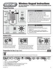
17 <strong>AXNET</strong> <strong>Browser</strong> <strong>Interface</strong> Navigation TreeThe following is the navigation tree for the <strong>AXNET</strong> <strong>Browser</strong> <strong>Interface</strong>.Numbers in parenthesis after major functionality indicate the number ofentries available for that feature. Items underlined in blue indicate thedefault value for the parameter.28MAINPRIORITY ACCESS OPENPRIORITY ACCESS CLOSEINSTALLATION NAME (My installation)EVENT LOG (4 NODES)GO TO (Page 1)SCROLL TO MOST RECENT EVENTBACKUP/DOWNLOADBACKUPDOWNLOAD EVENT LOG RECORDSCONTROLLER ([1] My Controller 1)FROM DATETO DATECREDENTIALSBLOCK CARDS (1-24)BEGINENDFACILITY CODE (1-255,---)NAMEBLOCK TRANSMITTERSBEGINENDFACILITY CODE (0-15,--)NAMEREPORTSSYSTEM REPORTNETWORK REPORTRESTART SUBMIT QUEUEDATABASE RESYNCCARDHOLDERSCARDSBLOCKSALL BLOCK LEARNEDSINGLE LEARNEDTRANSMITTERSBLOCKSALL BLOCK LEARNEDSINGLE LEARNEDENTRY CODESDIRECTORY CODESCONFIGURATIONLOGOUTLOGOUT AND HANG UPCHANGE OPERATORCARDHOLDERSCARDHOLDERSFIND BY ALPHABETALLA-ZFIND BY LAST NAMEINCLUDE CARDHOLDER SETALLALL ACCESSCARDHOLDER SET 1-32ADD CARDHOLDERFIRST NAMELAST NAMESTREETCITYSTATEZIPHOME PHONEWORK PHONENEVER EXPIRES (ENABLED/DISABLED)EXPIRATION DATESUSPEND CARDHOLDER (ENABLED/DISABLED)CARDHOLDER SETALL ACCESSCARDHOLDER SET 1-32CARDSSINGLECARD IDFACILITY CODE (1-255, ---)BLOCKCARD IDTRANSMITTERSSINGLECARD IDFACILITY CODE (0-15,---)BLOCKCARD IDENTRY CODESENTRY CODEDIRECTORY CODESDIR CODETENANT NAMETELEPHONEEXTENDED TALK TIME (ENABLED/DISABLED)DIRECTORY SUBSETSA (ENABLED/DISABLED)B (ENABLED/DISABLED)C (ENABLED/DISABLED)D (ENABLED/DISABLED)CARDHOLDER SETSNAME (CARDHOLDER SET n)SUSPENDED (ENABLED/DISABLED)TIME ZONESZONE (1-2)ALL ACCESSZONES 1-8VALIDATION GROUPGROUP (1-2)NOT ASSIGNEDALL ACCESSVALIDATION GROUP 1-8GROUP (3-4)NOT ASSIGNEDALL ACCESSVALIDATION GROUP 1-8ANTI-PASSBACKNONETIMEDBATCH ENTRY (10)CARDHOLDER SETALL ACCESSCARDHOLDER SET 1-32FIRST NAMELAST NAMEHOME PHONEDIRECTORY CODEENTRY CODECARD IDCARD FACILITY CODE (1-255,---)TRANSMITTER IDTRANSMITTER FACILITY CODE (0-15,--)ACTIVE (ENABLED/DISABLED)GLOBAL SETTINGSVALIDATION GROUPS (8)NAME (Validation Group n)DOOR SCHEDULEALL ACCESS1-8TIME ZONE (1-2)ALL ACCESS1-8TIME ZONES (8)MON-FRI (ENABLED/DISABLED)SAT-SUN (ENABLED/DISABLED)HOLIDAYS (ENABLED/DISABLED)TIME PERIOD (1-2)START TIMEEND TIMEDOOR SCHEDULES (16, 4 PER NODE)SCHEDULE1-8 (ENABLED/DISABLED)BUTTON SCHEDULESRELAY ANONEANYLEFTRIGHTTOPTOP & LEFTTOP & RIGHTBOTTOM LEFTBOTTOM RIGHTRELAY BNONEANYLEFTRIGHTTOPTOP & LEFTTOP & RIGHTBOTTOM LEFTBOTTOM RIGHTRELAY CNONEANYLEFTRIGHTTOPTOP & LEFTTOP & RIGHTBOTTOM LEFTBOTTOM RIGHTRELAY DNONEANYLEFTRIGHTTOPTOP & LEFTTOP & RIGHTBOTTOM LEFTBOTTOM RIGHTOPERATORS (4)NAME (Operator 1: <strong>Linear</strong>)PASSWORD (Operator 1: 123456)PRIVILIEGESOPERATORSUPERVISORADMINISTRATORCUSTOM LABELS (4)NAMEDOWNLIGHT TIMEON TIMEOFF TIMEEXPIRING HOLIDAYS (10)MONTHDAYYEARDELETE (ENABLED/DISABLED)NON-EXPIRING HOLIDAYS (10)MONTHDAYDELETE (ENABLED/DISABLED)FACILITY CODESTRANSMITTER (8)0-15CARD (8)0-15TELEPHONE DIRECTORYPRIORITY ACCESS PASSWORD (123456)TALK TIME (0-255, 60)POSTAL KEY DOORDOOR ADOOR BDOOR CDOOR DPBX DIALING DIGITOFF0-9DIRECTORY BEGINNING ATBEGINNING (A)MIDDLE (M)DIRECTORY CODE LENGTH (2, 3, 4)ENTRY CODE LENGTH (2, 3, 4, 5, 6)ANTI-PASSBACK TIMENONE1-4 MINDISPLAY MESSAGES (40)MESSAGEALIGNCENTERLEFTAUTO TIME SYNCDISABLED12:00 AM - 11:00 PMNETWORKINGNETWORK CONFIGURATION (1-11)Figure 3 - <strong>AXNET</strong> <strong>Browser</strong> Application Navigation TreeCONTROLLERS (4)REAL-TIME CONTROLLOCK OPENLOCK CLOSEUNLOCKTRIGGERGET CONTROLLER TIMESYNC TO COMPUTERGET CONTROLLER TIMESETUPCONTROLLER NAME (My Controller 1)CONTROLLER PASSWORD (123456)RADIO DIRECTIONNONEINKEYPAD STRIKE OUTDISABLED1-7DOOR AJAR TIME0-255 SECONDS, 60 SECONDSDAYLIGHT SAVINGS (ENABLED/DISABLED)ENABLE MODEM ANSWER (ENABLED/DISABLED)DIRECTORY SUBSETS (A, B, C, D)RELAYS (4)NAME (Access n)ACTIVATION TIME (2 SECONDS)TELEPHONE DIGITNONE1-9, 9TIMING MODETIMEPULSETOGGLELATCHOPERATIONCONTROLSHUNTALARMCCTVAUTO OPEN TIME ZONES (2)NOT ASSIGNED1-8ASSOCIATIONSA-D (ENABLED/DISABLED)PRIORITY ACCESS (ENABLED/DISABLED)MODEMINIT STRING 1 (ATH0E0S0=0Q0&G17&H2)INIT STRING 2 (ATH0)TERMINATION STRING (ATH0)OBSTACLE TRANSMITTER (2)FACILITY CODE (0-15)TRANSMITTER ID (0)NAMESUSPENDED (ENABLED/DISABLED)REMOTE DEVICES (7)DEVICES (1-4)DEVICENONEKEYPADRADIOWIEGAND 26WIEGAND 30WIEGAND 31CONTROL CHANNELDOOR ADOOR BDOOR CDOOR DDIRECTIONNONEINOUTNEUTRALOPTIONSA (ENABLED/DISABLED)B (ENABLED/DISABLED)C (ENABLED/DISABLED)D (ENABLED/DISABLED)NAMEDEVICE 7DEVICEPHONECONTROL CHANNELDOOR ADOOR BDOOR CDOOR DDIRECTIONNONEINOUTNEUTRALOPTIONSA (ENABLED/DISABLED)B (ENABLED/DISABLED)C (ENABLED/DISABLED)D (ENABLED/DISABLED)NAMEDEVICES (8,9)DEVICENONEWIEGAND 26WIEGAND 30WIEGAND 31CONTROL CHANNELDOOR ADOOR BDOOR CDOOR DDIRECTIONNONEINOUTNEUTRALOPTIONSA (ENABLED/DISABLED)B (ENABLED/DISABLED)C (ENABLED/DISABLED)D (ENABLED/DISABLED)NAME
18 <strong>AXNET</strong> <strong>Browser</strong> <strong>Interface</strong> <strong>Screen</strong> <strong>Shots</strong> <strong>and</strong> <strong>Descriptions</strong>18.1 Main <strong>Screen</strong>This is the default screen when the browser is launched. Priority accessis controlled from this screen, <strong>and</strong> if the controller time is different fromthe PC time, an additional button is displayed for synchronizing the PCtime to the controller time.When the controller time isdifferent from the PC time, thisbutton will be displayedPriority access controls are availablehere. Priority access relays can beassigned by going to Controllers ->My Controller (n) -> Relays<strong>Screen</strong> Shot 18.118.2 Cardholders> Cardholders <strong>Screen</strong>Cardholders can be searched by alphabet or lastname, <strong>and</strong> can be further fi ltered by cardholder sets.18.3 Cardholders> Add Cardholders <strong>Screen</strong>New cardholders can be added in this browser screen.The following information can be added:First Name: The cardholder’s fi rst name (maximum24 characters).Last Name: The cardholder’s last name (maximum 24characters).Street: The cardholder’s street address (maximum 24characters).City: The cardholder’s city (maximum 10 characters).State: The cardholder’s state (pulldown menu).Zip: The cardholder’s zip code (maximum 10 digits).Home Phone: The cardholder’s home phone number(maximum 10 digits).Work Phone: The cardholder’s work phone number(maximum 10 digits).Never Expires: Checked if the cardholder is does nothave an expiration date.Expiration Date: Expiration date for the cardholder.Requires the Never Expires radio box to be checked.Suspend Cardholder: Makes the cardholder entryinactive.Cardholder Set: Cardholder set to be used for thecardholder. Used to restrict access by time <strong>and</strong> doorlocation.Custom Fields: Custom fi elds become visible whenlabels are applied to the Custom fi elds (see Section18.15, Global Settings> Custom Labels).After the “Submit” button has been pressed, <strong>and</strong>the cardholder entry validated, additional fi elds willbecome visible, so that credentials can be entered.<strong>Screen</strong> Shot 18.2<strong>Screen</strong> Shot 18.3A<strong>Screen</strong> Shot 18.3B29
<strong>AXNET</strong> <strong>Browser</strong> <strong>Interface</strong> <strong>Screen</strong> <strong>Shots</strong> <strong>and</strong> <strong>Descriptions</strong> (Continued)18.3.1 Directory CodesWhen the Directory Code button is pressed toconfi gure the cardholder for directory codes for displayon AE1000Plus <strong>and</strong> AE2000Plus units, the followingadditional fi elds will be displayed:Dir Code: The next available directory code will beautomatically fi lled in this fi eld. The data in this fi eldcan be overridden by entering a new directory code.The maximum number of digits that can be entered inthis fi eld is determined by the Directory Code Lengthfi eld in the Global Settings->Telephone Directory page(see Section 18.19, Global Settings> TelephoneDirectory).Tenant Name: The tenant name derived from thefi rst <strong>and</strong> last name fi elds for the cardholder will beautomatically fi lled in this fi eld as “Last Name FirstName”. The data in this fi eld will be displayed on thepanel as the tenant name. The data in this fi eld can beoverridden by entering a new name to be associatedwith the directory code. The maximum length of thisfi eld is 24 characters.Telephone: The data in the Home Phone number fi eldfor the cardholder will be automatically fi lled in this fi eld.The data in this fi eld will be used by the controller todial the tenant. The data in this fi eld can be overriddenby entering a new phone number to be associated withthe directory code. The maximum length of this fi eld is10 digits.Ext Talk Time: When enabled, the cardholder /directory code will be allowed double the amount ofst<strong>and</strong>ard talk time.Directory Subsets: In networked installations withmultiple AE1000Plus or AE2000Plus telephone entrysystems, it is possible to determine which directorynames are displayed on the individual telephone entrysystems. Each cardholder can be assigned to any orall four directory subsets. Check the directory subsetsthat you would like to be displayed on this telephoneentry.18.3.2 Entry CodesWhen the Entry Code button is pressed to confi gurethe cardholder for keypad entry, the following additionalfi eld will be displayed:Entry Code: The keypad entry code associated withthis cardholder is added here. The maximum numberof digits that can be entered in this fi eld is determinedby the Entry Code Length fi eld in the Global Settings->Telephone Directory page (see Section 18.19,Global Settings> Telephone Directory).<strong>Screen</strong> Shot 18.3.1<strong>Screen</strong> Shot 18.3.230
<strong>AXNET</strong> <strong>Browser</strong> <strong>Interface</strong> <strong>Screen</strong> <strong>Shots</strong> <strong>and</strong> <strong>Descriptions</strong> (Continued)18.3.3 Block TransmittersBlock coded transmitters can be entered from thispage. Facility codes <strong>and</strong> IDs are checked for duplicatesbefore confi rmation of assignment. For a block codedtransmitter, block assignments must be done fi rst(see Section 18.9, Credentials> Block Transmitters<strong>Screen</strong>).18.3.4 Single TransmittersSingle transmitters can be entered from this page.Facility codes <strong>and</strong> IDs are checked for duplicatesbefore confi rmation of assignment.<strong>Screen</strong> Shot 18.3.318.3.5 Block CardsBlock coded cards can be entered from this page.Facility codes <strong>and</strong> IDs are checked for duplicatesbefore confi rmation of assignment. For a block codedcard, block assignments must be done fi rst (seeSection 18.8 Credentials> Block Cards <strong>Screen</strong>).<strong>Screen</strong> Shot 18.3.418.3.6 Single CardsSingle cards can be entered from this page. Facilitycodes <strong>and</strong> IDs are checked for duplicates beforeconfi rmation of assignment.<strong>Screen</strong> Shot 18.3.5<strong>Screen</strong> Shot 18.3.631
<strong>AXNET</strong> <strong>Browser</strong> <strong>Interface</strong> <strong>Screen</strong> <strong>Shots</strong> <strong>and</strong> <strong>Descriptions</strong> (Continued)18.4 Cardholders> Cardholder Sets <strong>Screen</strong>Cardholder Sets allow cardholders to be organized intogroups. Up to four validation groups <strong>and</strong> two time zones can beassigned to each cardholder set. Also, anti-passback rules maybe assigned to a cardholder set. It may be desirable to createa cardholder set for cardholders that share the same accessrequirements, such as, day shift <strong>and</strong> night shift if <strong>AXNET</strong> is usedin an industrial application. In a gated community application,it may be desirable to create a cardholder set for residents, acardholder set for employees <strong>and</strong> a cardholder set for vendors.To add a cardholder set, fi rst assign a name to the cardholderset. Time zones <strong>and</strong> validation groups can then be modifi ed asfollows:Rules for Validation Groups <strong>and</strong> Time Zones:1. Up to 4 different validation groups <strong>and</strong> 2 different timezones per cardholder set may be assigned.2. Validation group ALL ACCESS is for 24/7 access to alldoors.3. Validation group NO ACCESS does not allow access toany doors.4. To use the time zones available in the cardholder set, avalidation group must fi rst be defi ned with ALL ACCESSfor both time zones, <strong>and</strong> then assigned to the cardholderset. Time zones defi ned directly in the cardholder set willnow take effect.Timed anti-passback means that once a cardholder hasbeen granted access, they will not be granted access for apredetermined amount of time (1 – 4 minutes). If a cardholderattempts to gain access before the anti-passback time hasexpired, access will be denied <strong>and</strong> an anti-passback violation willbe logged into the event log. For timed anti-passback to apply fora device, the DIRECTION of the device must be set to IN.<strong>Screen</strong> Shot 18.432
<strong>AXNET</strong> <strong>Browser</strong> <strong>Interface</strong> <strong>Screen</strong> <strong>Shots</strong> <strong>and</strong> <strong>Descriptions</strong> (Continued)18.5 Cardholders> Batch Entry <strong>Screen</strong>The batch entry screen allows the entry of up to 10 cardholders inone submit cycle, quickening the entry of multiple cardholders.It is strongly recommended that the installation setup for accessrights be completed before using batch entry method of addingcardholders (set up time zones, validation groups <strong>and</strong> cardholdersets). Otherwise, it will become necessary later to make changesto set the cardholder set, one cardholder at a time.Any error in the batch mode screen will cause the submittal of allentries to fail. Errors will be displayed in a pop-up display, one ata time, as shown in the <strong>Screen</strong> Shot 18.5A.The batch submittal will be complete when all errors arecorrected.The following are the fi elds that can be entered for eachcardholder in batch mode entry.Cardholder Set: Cardholder set to be used for the cardholder.Used to restrict access by time <strong>and</strong> door location.First Name: The cardholder’s fi rst name (maximum 24characters).Last Name: The cardholder’s last name (maximum 24characters).Home Phone: The cardholder’s home phone number (maximum10 digits).Directory Code: The next available directory code will beautomatically fi lled in this fi eld. The data in this fi eld can beoverridden by entering a new directory code. The maximumnumber of digits that can be entered in this fi eld is determinedby the Directory Code Length fi eld in the Global Settings->Telephone Directory page (see Section 18.19, GlobalSettings> Telephone Directory).Entry Code: The keypad entry code associated with thiscardholder is added here. The maximum number of digits thatcan be entered in this fi eld is determined by the Entry CodeLength fi eld in the Global Settings->Telephone Directory page(see Section 18.19, Global Settings> Telephone Directory).Card: The ID for an unused single card. Unused block codedcard ID’s will not be allowed.Fac Code: The facility code for the card. A “---“ selection willcause the panel to ignore the facility code when validating thiscard.Transmitter: The ID for an unused single transmitter. Unusedblock coded transmitter ID’s will not be allowed.Fac Code: The facility code for the transmitter. A “--“ selectionwill cause the panel to ignore the facility code when validatingthis transmitter.Active: When unchecked, makes the cardholder entry inactive.<strong>Screen</strong> Shot 18.5A<strong>Screen</strong> Shot 18.5B33
<strong>AXNET</strong> <strong>Browser</strong> <strong>Interface</strong> <strong>Screen</strong> <strong>Shots</strong> <strong>and</strong> <strong>Descriptions</strong> (Continued)18.6 Eventlog <strong>Screen</strong>Event logs for each controller can be viewed using the Eventlogfunction. This function is useful in viewing recent events thathave occurred on the controller.Event logs are available for the connected controller or thosecontrollers that are linked to the connected controller via RS-485connection. To retrieve event logs from remote controllersaccessible via modem, a dial-up connection must be establishedwith the remote controller. When an event log retrieval isattempted with a controller not accessible, then the pop-upshown in <strong>Screen</strong> Shot 18.6B will be displayed.To consolidate event logs from all controllers into a single eventlog that is sorted in reverse chronological order, then the <strong>AXNET</strong>PC Software application must be used (see Sections 16.2.4,Download Eventlog, <strong>and</strong> 16.3, Eventlog Reports).<strong>Screen</strong> Shot 18.6A<strong>Screen</strong> Shot 18.6B18.7 Backup/Download <strong>Screen</strong>Database backups <strong>and</strong> event log downloads can be performedfrom this screen. It is highly recommended that periodic backupsof the database be performed as a preventative measure againstdata loss.18.7.1 BackupTo initiate a backup of the database in the controller,click on the “Backup” button.Click on the “Save” button to continue.Make any modifi cations to the path <strong>and</strong> fi le name, <strong>and</strong>then click on the “Save” button.A pop-up display will indicate the download progress.A pop-up will be displayed when the download iscomplete. Click on the “Close” button to complete thedownload session.18.7.2 Download Eventlog RecordsTo initiate an eventlog download for a controller, selectthe controller to download the eventlog from, select thedate range, <strong>and</strong> then click on the “Download” button.Click on the “Save” button to continue.Make any modifi cations to the path <strong>and</strong> fi le name, <strong>and</strong>then click on the “Save” button.A pop-up display will indicate the download progress.A pop-up will be displayed when the download iscomplete. Click on the “Close” button to complete thedownload session.<strong>Screen</strong> Shot 18.7.1<strong>Screen</strong> Shot 18.7.234
<strong>AXNET</strong> <strong>Browser</strong> <strong>Interface</strong> <strong>Screen</strong> <strong>Shots</strong> <strong>and</strong> <strong>Descriptions</strong> (Continued)18.8 Credentials> Block Cards <strong>Screen</strong>Block cards are added as a range of cards with starting <strong>and</strong>ending numbers. <strong>AXNET</strong> supports up to 24 blocks. Each blockcan contain up to 1,600 cards.Block cards are provided in Block Code format. The cards aresequentially coded in the manufacturing process. Starting <strong>and</strong>ending numbers for the block are required to program the blocks,along with the facility code for the block.NOTE: To associate a card to a validation group, the cardmust be assigned to a cardholder. Up to four validationgroups are assigned to each cardholder set. Therefore everycardholder will have the same restrictions that belong to theselected validation group(s).To add a card block in <strong>AXNET</strong>, enter the starting ID of the blockin the “Begin” fi eld, <strong>and</strong> the ending ID of the block in the “End”fi eld. Select the facility code of the block with the pull-down list.When “---“ is selected as the facility code entry, the facility codewill be ignored for authentication purposes.Enter a name to identify the card block (up to 24 characters),<strong>and</strong> then click on the “Submit” button. <strong>AXNET</strong> will check whetherthere are any overlaps with existing blocks or assigned singlecards. If there is any overlap, then the submission with fail witha pop-up message displayed describing the problem, as shownin <strong>Screen</strong> Shot 18.8B.Ensure that there are no overlaps by examining assigned cardblocks <strong>and</strong> by examining the single learned cards report. Deletethe overlapping entries <strong>and</strong> submit again.<strong>Screen</strong> Shot 18.8A<strong>Screen</strong> Shot 18.8B35
<strong>AXNET</strong> <strong>Browser</strong> <strong>Interface</strong> <strong>Screen</strong> <strong>Shots</strong> <strong>and</strong> <strong>Descriptions</strong> (Continued)18.9 Credentials> Block Transmitters <strong>Screen</strong>Block transmitters are added as a range of transmitters withstarting <strong>and</strong> ending numbers. <strong>AXNET</strong> supports up to 24 blocks.Each block can contain up to 1,600 transmitters.Block transmitters are provided in Block Code format. Thetransmitters are sequentially coded in the manufacturingprocess. Starting <strong>and</strong> ending numbers for the block are requiredto program the blocks, along with the facility code for the block.NOTE: To associate a transmitter to a validation group, thetransmitter must be assigned to a cardholder. Up to fourvalidation groups are assigned to each cardholder set.Therefore every cardholder will have the same restrictionsthat belong to the selected validation group(s).To add a transmitter block in <strong>AXNET</strong>, enter the starting ID of theblock in the “Begin” fi eld, <strong>and</strong> the ending ID of the block in the“End” fi eld. Select the facility code of the block with the pull-downlist. When “--“ is selected as the facility code entry, the facilitycode will be ignored for authentication purposes.Enter a name to identify the card block (up to 24 characters),<strong>and</strong> then click on the “Submit” button. <strong>AXNET</strong> will check whetherthere are any overlaps with existing blocks or assigned singletransmitters. If there is any overlap, then the submission with failwith a pop-up message displayed describing the problem, asshown in <strong>Screen</strong> Shot 18.9B.Ensure that there are no overlaps by examining assignedtransmitter block entries <strong>and</strong> by examining the single learnedtransmitters report. Delete the overlapping entries submit again.Please note that transmitter blocks cannot be deleted untilall assigned entries within the block range are removed. The“Delete” button to the left of the block entry will not be visible forthose transmitter blocks that have cardholders assigned withinthe block range.<strong>Screen</strong> Shot 18.9A<strong>Screen</strong> Shot 18.9B36
<strong>AXNET</strong> <strong>Browser</strong> <strong>Interface</strong> <strong>Screen</strong> <strong>Shots</strong> <strong>and</strong> <strong>Descriptions</strong> (Continued)18.10 Global Settings> Validation Groups <strong>Screen</strong>Validation Groups are often called security levels, <strong>and</strong> allowsthe restriction of access of a cardholder by date/time <strong>and</strong> door.Typically, validation groups are set up for groups of people withthe same access requirements. For example, a validation groupcan be set up that allows the employees that work the day shiftin a plant to have access to the main entrance during the day,but not on weekends. This same group, once inside the building,can have access to the tool room or the cafeteria only duringthe hours specifi ed in the validation group. <strong>AXNET</strong> supports 8different validation groups.Group: A name that best describes the validation group can beentered here (24 characters maximum).Door Schedule: The door schedule allows the restriction ofaccess of the cardholder to certain doors.18.11 Global Settings> Time Zones <strong>Screen</strong>Time Zones perform two functions in <strong>AXNET</strong>. A time zone canbe used to restrict the access of the cardholder by day <strong>and</strong> time.A time zone can also be used to hold open doors or gates viaan auto open time zone. In addition, holiday schedules can beimplemented to allow unique access requirements for holidays.<strong>AXNET</strong> supports up to 8 different time zones. Each time zonecan have up to two time periods. The periods allow the utilizationof one time zone to accomplish two actions during a 24 hourperiod. For example, if a gate is to be locked open in the morningfrom 6:00 A.M. until 8:00 A.M. <strong>and</strong> from 3:00 P.M. until 6:00 P.M.,this can be accomplished with one time zone by creating aperiod for the morning <strong>and</strong> a period for the afternoon.To enable a time zone, fi rst check the days of the week thatthe time zone is to valid <strong>and</strong>/or check “H” if the time zone isto enabled for holidays. Holiday schedules can be set in theExpiring Holidays <strong>and</strong> Non-Expiring Holidays browser panels(see Sections 18.17, Global Settings> Expiring Holidays; <strong>and</strong>18.18, Global Settings> Non-Expiring Holidays).Set the start <strong>and</strong> end times that the time zone is active in 24-hourformat. To disable a time zone set the start <strong>and</strong> end times forboth time periods to 00:00.18.12 Global Settings> Door Schedules <strong>Screen</strong>Door Schedules allow the restriction of access of the cardholderto certain doors (relays). <strong>AXNET</strong> supports up to 8 different doorschedules.If there are more than one node present within the network,there will be the ability to restrict access to each door via thedoor schedule. Check each door on the browser panel to beassociated with a specifi c door schedule.18.13 Global Settings> Button ScheduleButton Schedules allow changes to be made in the way multiplebutton transmitters react within the system. By default, a twobuttontransmitter will activate the A & B relays. A four-buttontransmitter will activate all four relays. Using button schedules,relays can be re-confi gured to have them activate via a buttoninstead of via the default. This is an advanced feature that shouldonly be used when necessary. Click the “Submit” button afterconfi guration of the Button Schedule is completed.<strong>Screen</strong> Shot 18.10<strong>Screen</strong> Shot 18.11<strong>Screen</strong> Shot 18.12<strong>Screen</strong> Shot 18.1337
<strong>AXNET</strong> <strong>Browser</strong> <strong>Interface</strong> <strong>Screen</strong> <strong>Shots</strong> <strong>and</strong> <strong>Descriptions</strong> (Continued)18.14 Global Settings> Operators <strong>Screen</strong>Operator user names <strong>and</strong> passwords can be set in this browserpanel. Currently, the all operators will have administratorprivileges (access to all <strong>AXNET</strong> features) regardless of the“Privileges” setting.Please note that the user name <strong>and</strong> password are case sensitive,<strong>and</strong> must be entered exactly as specifi ed in this browser pagefor the dial-up access or direct serial connection authentication.18.15 Global Settings> Custom LabelsThere are four user-defi nable fi elds provided that are displayedin the cardholder screen <strong>and</strong> in the Cardholder report.The custom label fi elds allow unique data to be added for eachcardholder, such as vehicle driven to work, vehicle color, license,etc.<strong>Screen</strong> Shot 18.1418.16 Global Settings> Downlight TimeDownlight On/Off Time. This will set the time that the downlighton the AM-KP <strong>and</strong> AM-KPI access control keypads will turn on<strong>and</strong> turn off. The option must be enabled in the keypads remotedevice setting (see Section 18.29, Controllers> My Controller(n)> Remote Devices). Enter the time in 24 hour format.<strong>Screen</strong> Shot 18.1518.17 Global Settings> Expiring HolidaysAn Expiring Holiday is a Holiday that will only work once. Anexpiring holiday could be an event that falls on the same DAY ofthe week every year.<strong>Screen</strong> Shot 18.1618.18 Global Settings> Non-Expiring HolidaysNon-Expiring Holidays will be effective on the same day everyyear. Typically non-expiring holidays fall on the same DATE everyyear.<strong>Screen</strong> Shot 18.1738<strong>Screen</strong> Shot 18.18
<strong>AXNET</strong> <strong>Browser</strong> <strong>Interface</strong> <strong>Screen</strong> <strong>Shots</strong> <strong>and</strong> <strong>Descriptions</strong> (Continued)18.19 Global Settings> Telephone DirectoryThis section applies to AE1000Plus or AE2000PlusTelephone Entry Systems ONLY.Priority Access Password: This is the 6-digit password thatmust be entered on a touch-tone phone to lock the relaysassigned as Priority Access open. The relays are assigned inthe Controllers -> Relays browser screen (see Section 18.26,Controllers> My Controller (n)> Relays).Priority Access comm<strong>and</strong>s can be entered from a touch-tonephone by entering the 6-digit password assigned here, followedby a single-digit comm<strong>and</strong>.The following comm<strong>and</strong>s are available:• “9” will lock open all relays assignedas a Priority Access relay.• “5” will unlock all relays assignedas a Priority Access relay.• “1” will lock open all relays assigned as aPriority Access relay for one hour.For example, if the Priority Access password is 123456, tolock the relays on for one hour, the following steps need to beperformed:1. From any touch tone phone, dial the phone number of themodem.2. When the controller answers the phone a beep will beheard.3. Enter 1 2 3 4 5 6 1 on your telephone keypad. A seriesof beeps as an acknowledgement will be heard if thepassword <strong>and</strong> comm<strong>and</strong> is accepted. The telephone entrysystem will then lock open all relays assigned as PriorityAccess for a period of one hour.Talk Time: Talk time is how much time the resident has tocommunicate with the guest via the telephone entry system. Thetalk time is programmable to between 0 <strong>and</strong> 255 seconds.Postal Key Door: If a postal switch is installed in the telephoneentry system, the Postal Key Door tells the controller which relayto activate.PBX Dialing Digit: If the system is connected to the phonecompany through a PBX <strong>and</strong> a certain digit must be dialed inorder to access an outside line, this digit may be selected (0-9)here. When assigning a directory code to a cardholder, the PBXdialing digit does not have be accounted for in order to accessan outside line.Directory Begins At: (AE1000Plus only) When a guestapproaches the telephone entry system <strong>and</strong> presses the # keyto enter the directory mode, the directory display can be set tostart in the beginning (A) or the middle (M).Directory Code Length: This sets the number of digits used toenter <strong>and</strong> display directory codes on the unit (2 to 4 digits). Forexample, if there are 600 residents with directory codes, at leasta 3-digit directory code length is required.Entry Code Length: This sets the number of digits required forthe input of entry codes (2 to 6 digits).<strong>Screen</strong> Shot 18.1939
<strong>AXNET</strong> <strong>Browser</strong> <strong>Interface</strong> <strong>Screen</strong> <strong>Shots</strong> <strong>and</strong> <strong>Descriptions</strong> (Continued)18.20 Global Settings> Anti-PassbackAnti-passback helps to prevent cardholders from using the samecredentials to gain unauthorized access. This is particularlyhelpful in installations with keypads.Anti-Passback Time: <strong>AXNET</strong> incorporates the ‘timed’ antipassbackmethod. Once the user has been granted access, theuser must wait until the anti-passback time expires before theywill be allowed access again. The time is programmable fromNONE to 4 minutes.To enable anti-passback, in addition to setting the time, theappropriate device must be enabled for anti-passback18.21 Global Settings> Display MessagesThis section applies to AE1000Plus or AE2000PlusTelephone Entry systems ONLY.Messages that are displayed on the telephone entry system canbe edited. There are a total of 40 messages that can be edited.To edit the display messages enter the new text (up to 16characters), choose the text alignment (left or center), <strong>and</strong> clickon the Submit button. All of the messages can be accessed byclicking on the “Go to” pulldown.The messages that are most frequently modifi ed are messages1 <strong>and</strong> 2. These messages are displayed on the front panel duringthe normal mode of operation.<strong>Screen</strong> Shot 18.20<strong>Screen</strong> Shot 18.2118.22 Global Settings> Auto Time SyncAuto Time Sync will enable the synchronization of the real-timeclock for all nodes in the installation at the specifi ed time.To enable the Auto Time Sync function, click on the pull-downmenu, <strong>and</strong> select a time for the controller to initiate the clocksynchronization.18.23 Global Settings> NetworkingThe network confi guration of the installation is set here. This isthe fi rst parameter that is set when setting up the installation. SeeSection 13, Network Installation Basics, for more details.<strong>Screen</strong> Shot 18.22<strong>Screen</strong> Shot 18.2340
<strong>AXNET</strong> <strong>Browser</strong> <strong>Interface</strong> <strong>Screen</strong> <strong>Shots</strong> <strong>and</strong> <strong>Descriptions</strong> (Continued)18.24 Controllers> My Controller (n)The main screen for each of the controllers provide real-timecontrol of the relays, as well as a facility to synchronize thecontroller real-time clock with the PC clock.To initiate action on the relays, the appropriate buttons need tobe clicked, followed by a click of the “Submit” button. If a mistakeis made in the setting of the relay states prior to issuing a Submitcomm<strong>and</strong>, then clicking on the “Clear” button will clear all pendingrelay actions. Real-time control of relays on the remote nodes arepossible as well. Select the appropriate remote controller, clickon the buttons to set the appropriate relay state, <strong>and</strong> then clickon the “Submit” button. Then to initiate real-time control on theremote controllers, it is necessary to log off <strong>and</strong> disconnect fromcontroller (see Section 18.38, Logout> Logout <strong>and</strong> Hangup).The following are descriptions of real-time control options for the relays:Lock Open: this will energize the relay <strong>and</strong> lock the relay state.Lock Close: this will de-energize the relay <strong>and</strong> lock the relaystate. The two-digit LED display on the controller board willindicate the relays that are lock closed as shown in Figure 4.Unlock: this will de-energize the relay <strong>and</strong> unlock the relay state.Trigger: this will energize the relay for the length of time setby the activation time (see Section 18.26, Controllers> MyController (n)> Relays), then de-energize the relay.18.25 Controllers> My Controller (n)> SetupThe basic controller confi guration is assigned here.Controller Name: This is the name assigned to the controller(maximum 23 characters).Controller Password: This is the password used to authenticatecontroller to controller communications.Radio Direction (only applicable for AE1000Plus <strong>and</strong>AE2000Plus): This setting is used in anti-passback applications.The options are:••NONE: This device will not be used todetermine anti-passback direction.IN: This device will be used as an IN devicein a timed anti-passback application.Keypad Strike Out: This is where the number of invalid keypadattempts before keypad lockout occurs is confi gured. The keypadwill remain locked for a period of 1 minute when the specifi ednumber of invalid attempts occurs. The number of invalidattempts before lockout is programmable between 1 <strong>and</strong> 7. Todisable this feature, set the parameter to Disabled.Door Ajar Time: This is the amount of time that the door canremain open before a relay set for alarm is activated.Daylight Savings: If the installation is in an area that practices DaylightSaving Time, please leave the Daylight Savings box checked.Enable Modem Answer: When the box is not checked (checkedby default), the on-board modem will not auto-answer.Directory Subsets: In networked installations with multipleAE1000Plus or AE-2000 telephone entry systems, it is possibleto determine which directory names are displayed on theindividual telephone entry systems. Each cardholder can beassigned to any or all four directory subsets. This is done in thecardholder screen. Check the directory subsets that are to bedisplayed on this controller.<strong>Screen</strong> Shot 18.2405 = Relay A is locked closed06 = Relay B is locked closed07 = Relay C is locked closed08 = Relay D is locked closedFigure 4. Relay Status Display Indication<strong>Screen</strong> Shot 18.2541
<strong>AXNET</strong> <strong>Browser</strong> <strong>Interface</strong> <strong>Screen</strong> <strong>Shots</strong> <strong>and</strong> <strong>Descriptions</strong> (Continued)18.26 Controllers> My Controller (n)> RelaysIndividual relays on the node are confi gured using this browserwindow.There are four relays on the controller. Each relay is programmedindividually, <strong>and</strong> the following parameters can be changed:Name: This is the name associated with the relay. The name canbe up to 23 characters in length.Activation Time: This is the amount of time that the relay isactivated in seconds. This is only applicable in the timed modeof relay operation. Typically, a relay set to activate a mag lock orelectric strike will be set for around fi ve seconds. Two seconds isusually suffi cient for the average gate operator.Telephone Digit: This feature is only valid with AE1000Plus <strong>and</strong>AE2000Plus units. This is the key which the user will have topress on their touch-tone phone to grant access on a telephoneentry call. The programmable options are NONE or 1 – 9.Timing Mode: This selects the mode of operation for the relay.See the Relay Timing Modes Table.Operation: This parameter determines how the relay willfunction in the system. See the Relay Operation Table.Auto Open Time Zones: Time Zones can be assigned toautomatically lock open <strong>and</strong> unlock relays during specifi c timeperiods. Up to two time zones can be set per relay. For example,auto open time zones can be used if there is an entrance door orgate that is to be locked open in the morning when everyone iscoming to work <strong>and</strong> again when they are going home from work.A time zone can be specifi ed for a period that opens the gate inthe morning <strong>and</strong> another time zone can be specifi ed for a periodthat opens the gate in the afternoon. The time zones are set upin the Global Settings -> Time Zones browser page (see Section18.11 Global Settings> Time Zones <strong>Screen</strong>).Associations: Applicable when the relay control is set to Shuntor Alarm, actions on relays associated with a shunt or alarmrelay will cause this relay to be activated.Priority Access: When checked, these relays can be controlledfrom the main browser screen (see Section 18.1 Main <strong>Screen</strong>) orfrom the telephone for AE1000Plus <strong>and</strong> AE2000Plus controllers(see Section 18.19 Global Settings> Telephone Directory).42TIMING MODETimedPulseToggleLatchOPERATIONControlShuntAlarmObstacleCCTV<strong>Screen</strong> Shot 18.26RELAY TIMING MODESFUNCTIONThe relay stays activated for the specifi ed duration.The relay will trigger for 1/4 second.The relay will activate for the fi rst activation <strong>and</strong>release on the next activation.The relay will activate <strong>and</strong> remain activated untilreset at the control.RELAY OPERATIONFUNCTIONIn this mode, the relay will activate per the TimingMode <strong>and</strong> Activation Time parameters.When a relay is set for shunt, any of the other relaysmay be associated with this shunt relay. Relayassociations are made by checking the appropriaterelays in the Associations section. This shunt relaywill activate <strong>and</strong> remain activated as long as anyrelay associated with it is activated.If a relay is set for alarm, any of the other relaysmay be associated with this alarm relay. This alarmrelay follows the door ajar input of any of the relayassociated with it. The door ajar input changes whenthe door or gate remains open past the setting forDoor Ajar Time.If set for obstacle, the C relay will activate if awireless supervised gate edge transmitter (MGT) isprogrammed into transmitter 1 senses an obstruction.The D relay will activate if an MGT programmed intotransmitter 2 senses an obstruction.This feature is only applicable to AE1000Plus<strong>and</strong> AE2000Plus. When talking to a visitor via thetelephone entry system, the user can press “5” ontheir touch-tone phone to activate the relay set forCCTV. A CCTV camera at the entry point couldthen send an image back to the resident. CCTVequipment is sold separately.
<strong>AXNET</strong> <strong>Browser</strong> <strong>Interface</strong> <strong>Screen</strong> <strong>Shots</strong> <strong>and</strong> <strong>Descriptions</strong> (Continued)18.27 Controllers> My Controller (n)> ModemThis screen allows for the confi guration of the initialization <strong>and</strong>termination strings for the modem. These strings are confi guredspecifi cally for the modem installed in the controller unit, <strong>and</strong>should not be modifi ed unless instructed to do so.<strong>Screen</strong> Shot 18.2718.28 Controllers> My Controller (n)> Obstacle TransmitterUp to two MGT safety edge transmitters can be programmed pernode. The MGT is a wireless supervised gate edge transmitter.An edge sensor, such as a tape switch or a safety edge isconnected to the MGT. When the edge sensor strikes anotherobject, the MGT sends a signal to the controller. The controllersupervises the MGT for battery, status <strong>and</strong> tamper. Any of theseevents will cause the MGT report the trouble condition to thecontroller.Obstacle Transmitter 1 is associated with Relay C of thecontroller. To enable the association of obstacle transmitter 1with Relay C, Relay C, must be confi gured for Obstacle inthe Operation fi eld of the relay setup (see Section 18.26Controllers> My Controller (n)> Relays).Obstacle Transmitter 2 is associated with Relay D of thecontroller. To enable the association of obstacle transmitter 1with Relay D, Relay D, must be confi gured for Obstacle inthe Operation fi eld of the relay setup (see Section 18.26Controllers> My Controller (n)> Relays).Fac: The facility code of the MGT is entered here.ID: The ID code for the MGT is entered here.Name: The name associated with the obstacle transmitter isentered here (maximum 24 characters).Suspended: This box is checked if the obstacle transmitter isto be disabled.<strong>Screen</strong> Shot 18.2843
<strong>AXNET</strong> <strong>Browser</strong> <strong>Interface</strong> <strong>Screen</strong> <strong>Shots</strong> <strong>and</strong> <strong>Descriptions</strong> (Continued)18.29 Controllers> My Controller (n)> Remote DevicesUp to four remote devices can be connected to a node. On eachremote device, there is a rotary switch that is used to set eachdevice to a unique device address. During installation, eachremote device should have been assigned a unique deviceaddress.DV1 – DV9: Each remote device will have a unique deviceaddress set during installation. DV1 – DV4 <strong>and</strong> DV8 & DV9 arepossible device addresses. DV7 is used for type PHONE only<strong>and</strong> is always assigned to the keypad found on an AE1000Plusor AE2000Plus. DV8 is used for type Reader A <strong>and</strong> DV9 is usedfor type Reader B.Device: The <strong>AXNET</strong> device category of the remote device is sethere. The types of devices <strong>and</strong> their categories are listed in theRemote Device Categories Table.Control Channel: The relay that is to be activated when a validcredential is received is set here. More than one device mayactive the same relay, but a device may not active more than onerelay, with one exception. When the “Button” selection is madefor Radio type devices, a multi-button transmitter will activatedifferent relays as defi ned in Button Schedule settings (seeSection 18.13 Global Settings> Button Schedule). Pleasenote that setting any other device to the “Button” setting willcause none of the relays to be activated.Direction: This setting is used in anti-passback applications.The settings are shown in the Anti-passback Direction Settingstable.Options: Special device features are enabled <strong>and</strong> disabledusing these settings. Currently, the AM-KP, AM-KPI, <strong>and</strong> PHONEdevices are the only remote devices that have programmingoptions. The options are shown in the Keypad Device Options<strong>and</strong> Phone Device Options Tables.REMOTE DEVICE CATEGORIESCATEGORY <strong>AXNET</strong> DEVICE OPTIONS/NOTESKeypad AM-KP Entry Keypad YesKeypad AM-KPI Entry Keypad YesRadio AM-RRR Remote Radio Receiver NoneRadio AM-RPR Remote Proximity Receiver NonePhone Keypad on AE1000Plus or AE2000Plus YesWieg<strong>and</strong> 26 AM-CRI Card Reader <strong>Interface</strong> NoneWieg<strong>and</strong> 30 AM-CRI Card Reader <strong>Interface</strong> NoneWieg<strong>and</strong> 31 AM-CRI Card Reader <strong>Interface</strong> NoneDIRECTIONNONEINOUTNEUTRALOPTIONABCD<strong>Screen</strong> Shot 18.29ANTI-PASSBACK DIRECTION SETTINGSDESCRIPTIONThis device will not be used to determine anti-passbackdirection.This device will be used as an IN device in a timed antipassbackapplicationCurrently not supported.Currently not supportedKEYPAD DEVICE OPTIONSDESCRIPTIONKeypad Beeps OnDownlight Timing On. Keypad’s built-in downlight can be setto turn on <strong>and</strong> turn off at certain times by setting the start <strong>and</strong>end times in the Downlight Time browser panel (see Section17.16, Global Settings >Downlight Time)If enabled, it will cause the downlight to remain on 24 hours aday. By setting this option, Option B settings will be overridden.Keypad Beeps On44OPTIONABCDPHONE DEVICE OPTIONSDESCRIPTIONNot UsedNot UsedNot UsedKeypad Activates Dual Relays. When enabled, entry codesare entered on the keypad on AE1000Plus or AE2000Plusactivate specifi c relays> If the control channel for DV7 is set to RELAY A entry codesending with an EVEN number will activate RELAY A. Entrycodes ending with an ODD number will activate RELAY B.> If the control channel for DV7 is set to RELAY C, entry codesending with an EVEN number will activate RELAY C. Entrycodes ending with an ODD number will activate RELAY D.
<strong>AXNET</strong> <strong>Browser</strong> <strong>Interface</strong> <strong>Screen</strong> <strong>Shots</strong> <strong>and</strong> <strong>Descriptions</strong> (Continued)18.30 Reports> System ReportThis report displays all global settings, as well as controllerconfi gurations.<strong>Screen</strong> Shot 18.3018.31 Reports> Network ReportThe Network Report provides status of the communicationsbetween nodes, <strong>and</strong> provides a facility to restart the networkafter an issue has been reported <strong>and</strong> caused controller to gooffl ine:<strong>Screen</strong> Shot 18.31 shows that all nodes are on-line (Node Statusis OK), <strong>and</strong> that there are no pending comm<strong>and</strong>s in the Submitstatus queue.18.31.1 Restart Submit QueueIf there is a communication problem with one ofthe nodes, then the pop-up shown in <strong>Screen</strong> Shot18.31.1A will be displayed:<strong>Screen</strong> Shot 18.31.1A shows that one of the nodes isinaccessible. An additional button is displayed (“RestartSubmit Queue) to allow the panel operator to restart thenetwork communication (see <strong>Screen</strong> Shot 18.31.1B).<strong>Screen</strong> Shot 18.3118.31.2 Database ResyncIn <strong>AXNET</strong> mode of operation, it is essential that thedatabases in all of the controllers in the installationbe synchronized. <strong>AXNET</strong> automatically performssynchronization with other controllers when changesare made in Node 1. In the event that the state of thedatabase in the controllers become unknown, or if arestore of a backup is desired <strong>and</strong> synchronizationof the databases is required, the Database Resyncfeature is used. Database Resync will propagate theentire contents of a database to all of the controllersin the installation. Database Resync can only beinitiated from Node 1. Please also note that for largedatabases, the resync activity can take a considerableamount of time.<strong>Screen</strong> Shot 18.31.1A<strong>Screen</strong> Shot 18.31.1B45
<strong>AXNET</strong> <strong>Browser</strong> <strong>Interface</strong> <strong>Screen</strong> <strong>Shots</strong> <strong>and</strong> <strong>Descriptions</strong> (Continued)18.32 Reports> CardholdersThe Cardholder report provides Cardholders information inreport form.<strong>Screen</strong> Shot 18.3218.33 Reports> CardsVarious reports can be displayed for the cards.The report in <strong>Screen</strong> Shot 18.33A displays all card blocks thathave been defi ned.The report in <strong>Screen</strong> Shot 18.33B displays all IDs that have beendefi ned within the card block range.<strong>Screen</strong> Shot 18.33AThe report in <strong>Screen</strong> Shot 18.33C displays all single cards thatwere enrolled:<strong>Screen</strong> Shot 18.33B<strong>Screen</strong> Shot 18.33C46
<strong>AXNET</strong> <strong>Browser</strong> <strong>Interface</strong> <strong>Screen</strong> <strong>Shots</strong> <strong>and</strong> <strong>Descriptions</strong> (Continued)18.34 Reports> TransmittersVarious reports that can be displayed for the transmitters:The report in <strong>Screen</strong> Shot 18.34A displays all transmitter blocksthat have been defi ned.The report in <strong>Screen</strong> Shot 18.34B displays all IDs that have beendefi ned within the transmitter block range.<strong>Screen</strong> Shot 18.34AThe report in <strong>Screen</strong> Shot 18.34C displays all single transmittersthat were enrolled.<strong>Screen</strong> Shot 18.34B18.35 Reports> Entry CodesThe report in <strong>Screen</strong> Shot 18.35 displays all entry codes thathave been assigned to cardholders.<strong>Screen</strong> Shot 18.34C<strong>Screen</strong> Shot 18.3518.36 Reports> Directory CodesThe report in <strong>Screen</strong> Shot 18.36 displays all directory codesthat have assigned to cardholders, with the cardholder name,phone number to be dialed, whether or not extended talk time isenabled, <strong>and</strong> the directory subsets assigned displayed.<strong>Screen</strong> Shot 18.3647
<strong>AXNET</strong> <strong>Browser</strong> <strong>Interface</strong> <strong>Screen</strong> <strong>Shots</strong> <strong>and</strong> <strong>Descriptions</strong> (Continued)18.37 Reports> ConfigurationThis report displays the confi guration of the computer running<strong>AXNET</strong>, including the operating system version <strong>and</strong> the Javaversion. This report also displays the controller confi gurationincluding the controller type, embedded fi rmware revision,database revision, <strong>and</strong> network status. Finally, this reportdisplays the current database memory usage.18.38 Logout> Logout <strong>and</strong> HangupThis will cause <strong>AXNET</strong> to log out <strong>and</strong> hang up the PPPconnection. When this menu item is clicked, a pop-up dialogwill appear prompting whether to initiate a back-up (see <strong>Screen</strong>Shot 18.38B.If “OK” is clicked, then the browser will open the Backup/Download screen. Follow instructions in Section 18.7, Backup/Download <strong>Screen</strong>.<strong>Screen</strong> Shot 18.37<strong>Screen</strong> Shot 18.38A18.39 Logout> Change OperatorThe Change Operator screen allows the switching betweenoperators without having to disconnect <strong>and</strong> re-establish a PPPconnection.<strong>Screen</strong> Shot 18.38B<strong>Screen</strong> Shot 18.3948
19 Appendix - Definition of Front Panel Configuration ModesThe front panel display operation will be different between <strong>AXNET</strong> modeof operation <strong>and</strong> AccessBase mode of operation. The set-up mode canbe entered by pressing the UP <strong>and</strong> DOWN buttons simultaneously forabout 1 second. The controller will acknowledge with a beep whenentering the set-up mode.<strong>AXNET</strong> Mode (An 1.0 on power-up display)0.1. Assign Controller as Node 10.2. Assign Controller as Node 20.3. Assign Controller as Node 30.4. Assign Controller as Node 4A.b. Switch to AccessBase Mode of Operationb.L. ReservedC.L. Clear Controller DatabaseAccessBase Mode (Ab 2.5 on power-up display)0.1. Assign Controller as Node 10.2. Assign Controller as Node 20.3. Assign Controller as Node 30.4. Assign Controller as Node 40.5. Assign Controller as Node 50.6. Assign Controller as Node 60.7. Assign Controller as Node 70.8. Assign Controller as Node 8A.n. Switch to <strong>AXNET</strong> Mode of Operationb.L. ReservedC.L. Clear Controller Confi guration49
20 Appendix - Network ConfigurationsSolid lines between the controllers indicate RS-485 connections. Dashedlines between the controllers indicate modem connections.NETWORKCONFIGURATIONNUMBERDESCRIPTIONNETWORK CONFIGURATION TABLECONFIGURATION1Single Node2Two RS-485 Networked Nodes3Two Modem Nodes4Three RS-485 Networked Nodes5Two RS-485 Networked Nodes + OneModem Node6Three Modem Nodes7Four RS-485 Networked Nodes8Three RS-485 Networked Nodes +One Modem Node92 x Two RS-485 Networked Nodes10Two RS-485 Networked Nodes + TwoModem Nodes11Four Modem NodesCopyright © 2007 <strong>Linear</strong> LLC226505 A