SMATV Noise generator Ref. 5930
SMATV Noise generator Ref. 5930
SMATV Noise generator Ref. 5930

You also want an ePaper? Increase the reach of your titles
YUMPU automatically turns print PDFs into web optimized ePapers that Google loves.
<strong>SMATV</strong><br />
5<br />
3<br />
- 30 dB<br />
Generatore di Rumore<br />
15<br />
N o ise Ge n era tor<br />
Level Adx.<br />
<strong>Ref</strong>. <strong>5930</strong><br />
0 1<br />
8 2<br />
7 3<br />
6 5 4<br />
9<br />
0 - 10 dB<br />
5 - 2.150 MHz<br />
ON<br />
<strong>Noise</strong> <strong>generator</strong><br />
234796<br />
2<br />
<strong>Ref</strong>. <strong>5930</strong><br />
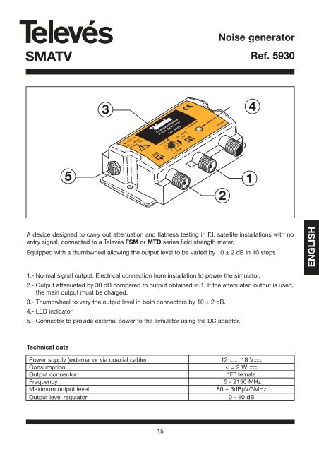
A device designed to carry out attenuation and flatness testing in F.I. satellite installations with no<br />
entry signal, connected to a Televés FSM or MTD series field strength meter.<br />
Equipped with a thumbwheel allowing the output level to be varied by 10 ± 2 dB in 10 steps<br />
1.- Normal signal output. Electrical connection from installation to power the simulator.<br />
2.- Output attenuated by 30 dB compared to output obtained in 1. If the attenuated output is used,<br />
the main output must be charged.<br />
3.- Thumbwheel to vary the output level in both connectors by 10 ± 2 dB.<br />
4.- LED indicator<br />
5.- Connector to provide external power to the simulator using the DC adaptor.<br />
Technical data<br />
Power supply (external or via coaxial cable) 12 ...... 18 V<br />
Consumption < = 2 W<br />
Output connector “F” female<br />
Frequency 5 - 2150 MHz<br />
Maximum output level 80 ± 3dBµV/3MHz<br />
Output level regulator 0 - 10 dB<br />
4<br />
1<br />
ENGLISH
<strong>SMATV</strong><br />
Checking an installation<br />
5498<br />
Power supply<br />
PWR<br />
<strong>Noise</strong><br />
<strong>generator</strong><br />
Generador ruido<br />
<strong>Noise</strong> Generator<br />
<strong>Ref</strong>. <strong>5930</strong><br />
Level Adx.<br />
5 - 2.150 MHz<br />
9<br />
0<br />
12<br />
-30 dB 8<br />
ON<br />
7 3<br />
6 5 4<br />
0 - 10 dB<br />
234796<br />
Verification of T03 headend<br />
C49 C52 C42 C61 C55 C58 C65-69<br />
5086<br />
TV antenna or<br />
cable signal<br />
Mixer<br />
TV socket<br />
16<br />
-30 dB<br />
Level Adx.<br />
9<br />
0<br />
1<br />
8 2<br />
7 3<br />
6 5 4<br />
0 - 10 dB<br />
Generador ruido<br />
<strong>Noise</strong> Generator<br />
<strong>Ref</strong>. <strong>5930</strong><br />
Measuring<br />
device signal<br />
input<br />
5 - 2.150 MHz<br />
ON<br />
234796<br />
<strong>Noise</strong> <strong>generator</strong><br />
<strong>Noise</strong><br />
<strong>generator</strong><br />
C55 C58<br />
C61<br />
<strong>Ref</strong>. <strong>5930</strong><br />
Measuring<br />
device signal<br />
input<br />
C65-69
<strong>SMATV</strong><br />
17<br />
<strong>Noise</strong> <strong>generator</strong><br />
<strong>Ref</strong>. <strong>5930</strong><br />
The noise <strong>generator</strong> can be powered by an mains adaptor, or by the meter via an RF cable. In order<br />
to do this simply select the pre-amplifier powering in the meter's corresponding menu.<br />
To access the pre-amplifier powering menu in the field strength meter, you can follow these steps:<br />
In the terrestrial band:<br />
CONFIG.<br />
MEASURE<br />
In the satellite band:<br />
CONFIG.<br />
MEASURE<br />
Or, press the fast button<br />
This will open the Powering window:<br />
PREAMPLIF.<br />
LNB &<br />
PREAMPLIF.<br />
It is advisable to select the power measurement in the FSM when working with the noise <strong>generator</strong>.<br />
Application examples:<br />
LNB<br />
A few applications of the noise <strong>generator</strong> are briefly explained below:<br />
1.- Checking the condition of a section of the cable before installing: By using the noise <strong>generator</strong><br />
and the FSM field meter it is possible to check the condition of a section of the cable<br />
before installing it.<br />
ENGLISH
<strong>SMATV</strong><br />
18<br />
<strong>Noise</strong> <strong>generator</strong><br />
<strong>Ref</strong>. <strong>5930</strong><br />
- Configure the FSM field meter to analyze mode, select Full Span and select the powering<br />
measurement.<br />
- Connect the noise <strong>generator</strong> to the FSM meter. Check that the generated noise spectrum<br />
is nearly flat. The longer the cable you are going to check, the bigger the powering<br />
produced by the noise <strong>generator</strong> should be. A small table with the recommended<br />
minimum powering, depending on the length of the cable to be checked, is shown<br />
below (the wire T100 -ref.2141 has been used as an example).<br />
Length of cable in metres (T100) Minimum output powering of the noise <strong>generator</strong> (dBuV)<br />
10 43<br />
25 47<br />
50 55<br />
75 62<br />
100 70<br />
150 80<br />
Select the adequate reference level on the meter. Note down the measurement of the powering in<br />
several frequencies along the terrestrial band, and then do the same with the satellite band. Likewise<br />
you must take into account the bandwidth and the resolution filter used in the measurement, as the<br />
powering measurements at the input and at the output should be measured with the minimum<br />
values for these parameters.<br />
In the next example we use the following frequencies as a reference:<br />
The terrestrial band: 200, 500 y 800 MHz<br />
The satellite band: 1000, 1750, 2150 MHz<br />
The powering measurements for the reference frequencies are (with BW=8 MHz and RBW=250<br />
KHzW):<br />
Frequency (MHz) Powering (dBuV)<br />
200 80.0<br />
500 78.5<br />
800 78.9<br />
1000 78.8<br />
1750 79.5<br />
2150 82.5<br />
In the used cable specifications, the attenuation per meter (dB/m), that the signal undergoes will<br />
appear. This attenuation varies with the frequency, growing as the frequency increases.
<strong>SMATV</strong><br />
In the following image you can see the signal at the input (in the terrestrial band):<br />
The terrestrial band The satellite banda<br />
19<br />
<strong>Noise</strong> <strong>generator</strong><br />
<strong>Ref</strong>. <strong>5930</strong><br />
In this example the T-100 (ref. 2141) interior/exterior cable, and 85 m for the length of the wire have<br />
been taken as a reference. The total attenuation is calculated by multiplying the attenuation/m by the<br />
length of the cable.<br />
Frequency (MHz) Attenuation (dB/m) Total attenuation (dB)<br />
200 0.08 6.8<br />
500 0.12 10.2<br />
800 0.15 12.75<br />
1000 0.18 15.3<br />
1750 0.24 20.4<br />
2150 0.27 22.95<br />
- Connect the noise <strong>generator</strong> to one end of the cable.<br />
- Connect the FSM meter to the other end of the cable, configure it in spectrum mode and<br />
select "Full Span". You will see that the spectrum of the received signal is no longer flat, but<br />
that the level decreases as the frequency increases, as shown in the following picture:<br />
ENGLISH
<strong>SMATV</strong><br />
The terrestrial band The satellite band<br />
20<br />
<strong>Noise</strong> <strong>generator</strong><br />
<strong>Ref</strong>. <strong>5930</strong><br />
- Check that the powering measurement in the FSM meter in all reference frequencies matches<br />
the theoretical frequencies depending on the length of the cable and the attenuation factors of<br />
the corresponding frequency, in other words, that for each powering measurement frequency<br />
should be:<br />
POWERINGoutput =POWERINGinput - TOTAL ATTENUATION<br />
In the example the powering measurements of the signal at the cable output should be approximately<br />
as follows:<br />
Frequency (MHz) Powering (dBuV)<br />
200 73.2<br />
500 68.3<br />
800 66.15<br />
1000 63.5<br />
1750 59.1<br />
2150 59.55<br />
2.- Assessment of the losses in the installation of any frequency between 15 and 2150 MHz (see the<br />
noise <strong>generator</strong> specifications): It is very useful to see that the distribution network reaches all<br />
the installation sockets without any losses.
<strong>SMATV</strong><br />
We will take a simple installation in a house as an example:<br />
21<br />
<strong>Noise</strong> <strong>generator</strong><br />
<strong>Ref</strong>. <strong>5930</strong><br />
- Firstly we have to select a series of reference frequencies and measure the power provided<br />
by the <strong>generator</strong> in each one of them (the same as in the previous example).<br />
In this example we have selected the following:<br />
Band Frequency (MHz)<br />
Return signal 20.00<br />
BI 55.25<br />
FM 99.00<br />
BS-b 120.00<br />
BIII-1 175.25<br />
BIII-2 274.25<br />
DAB 210.00<br />
BIV 471.25<br />
BIV-BV 607.25<br />
BV 855.25<br />
FI-1 950.00<br />
FI-2 1350.00<br />
FI-3 1750.00<br />
FI-4 2150.00<br />
ENGLISH
<strong>SMATV</strong><br />
22<br />
<strong>Noise</strong> <strong>generator</strong><br />
<strong>Ref</strong>. <strong>5930</strong><br />
The first thing we do is calculate the attenuation for all the sockets. In order to do this we have to<br />
take into account the metres of cable from the headend up to each of the sockets and the passive<br />
elements (separators and sockets).<br />
The tables with the specifications of each of the installation elements are shown below:<br />
*Splitters:<br />
Technical<br />
specifications<br />
<strong>Ref</strong>erence 5435 5436 5437 5438<br />
Freq. range 5-2400 MHz<br />
Attenuation IN-OUT (dB)<br />
5- 47 MHz<br />
47-862 MHz<br />
3,5<br />
4,5<br />
6,5<br />
7<br />
8<br />
7,5<br />
9,5<br />
8,5<br />
950 - 2400 MHz 5,5 9 9,5 9,5 .. 12<br />
Attenuation IN-OUT3 (dB)<br />
5 - 47MHz<br />
47 - 862 MHz<br />
-<br />
-<br />
6,5<br />
6,5<br />
-<br />
-<br />
10<br />
9,5<br />
950 - 2400 MHz - 7 - 9<br />
Rejection between outputs (dB)<br />
*T100 cable:<br />
5 - 862 MHz >15 >15 >17 >15<br />
950 - 2400 MHz >15 >15 >15 >15<br />
Max. voltage 40 V<br />
Max. current 300 mA<br />
<strong>Ref</strong>erences 2141 4357 2147 2155 2158 2150 4358 2151<br />
Outer sheat mat´l PVC PVC PVC PE PE PVC PVC PVC<br />
LSFH<br />
Max. outer diameter mm 6,6 6,6 6,6 6,6 6,6 6,6 6,6 6,6<br />
Color sheat white white black black black white white white<br />
Anti-migrating film - - si si si si si si<br />
Braid mat´l Cu Cu Cu Cu Cu Al Al Cu<br />
Outer conductor resistance ohm/Km 20 20 20 20 20 40 40 21<br />
Composition of overlapped<br />
between dielectric and fall<br />
mat´l Cu+Pt Cu+Pt Cu+Pt Cu+Pt Cu+Pt Al+Pt+Al Al+Pt+Al Cu+Pt<br />
Screening (EN50117) % >75 >75 >75 >75 >75 >75 >75 >75<br />
Dielectric mat´l Cu Cu Cu Cu Cu Cu Cu Cu<br />
Inner conductor resistance ohm/Km 20 20 20 20 20 20 20 18<br />
Max Inner conductor<br />
diameter<br />
m 1,13 1,13 1,13 1,13 1,13 1,13 1,13 1,12<br />
Capacitance pF/m 55 55 55 55 55 56,5 56,5 55<br />
Meters/packing m 100 250 100 100 250 100 250 100
<strong>SMATV</strong><br />
*T100 cable:<br />
*End sockets:<br />
23<br />
<strong>Noise</strong> <strong>generator</strong><br />
<strong>Ref</strong>. <strong>5930</strong><br />
Attenuation<br />
200 0,08 0,08 0,08 0,08 0,08 0,08 0,08 0,07<br />
500 0,12 0,12 0,12 0,12 0,12 0,13 0,13 0,12<br />
800 0,15 0,15 0,15 0,15 0,15 0,16 0,16 0,15<br />
Frequency 1000 0,18 0,18 0,18 0,18 0,18 0,19 0,19 0,17<br />
(MHz) dB/m 1350 0,21 0,21 0,21 0,21 0,21 0,22 0,22 0,20<br />
1750 0,24 0,24 0,24 0,24 0,24 0,25 0,25 0,23<br />
2050 0,27 0,27 0,27 0,27 0,27 0,28 0,28 0,25<br />
2150 0,27 0,27 0,27 0,27 0,27 0,29 0,29 0,26<br />
2300 0,28 0,28 0,28 0,28 0,28 0,30 0,30 0,27<br />
Insertion losses typ (dB)<br />
Salida<br />
Derivation losses typ (dB)<br />
DC pass<br />
<strong>Ref</strong>. Type<br />
MATV SAT-FI<br />
5-862 MHz 950-2150 MHz<br />
MATV SAT-FI 24v<br />
OUT<br />
5-862 MHz 950-2150 MHz 350 mA<br />
5226 TV-SAT --- ---<br />
R/TV<br />
SAT<br />
0,6<br />
---<br />
---<br />
1,5<br />
SAT IN<br />
As an example, we will calculate step by step the attenuation from the socket in Bedroom 2 on the<br />
2nd floor:<br />
Metres of cable T100 = 5+1+7 = 13 metres of cable<br />
The total attenuation will be:<br />
Attenuation splitter_5435 + Attenuation splitter_5438 + Attenuation cable + Attenuation socket<br />
The attenuation of each element will depend on the frequency, thus obtaining:<br />
Frequency = 20 MHz 3.5 + 9.5 + 13x0 + 0.6 = 13.6 dB<br />
Frequency = 55.25 MHz 4.5 + 8.5 + 13x0 + 0.6 = 13.6 dB<br />
Frequency = 99 MHz 4.5 + 8.5 + 13x0 + 0.6 = 13.6 dB<br />
Frequency = 120 MHz 4.5 + 8.5 + 13x0 + 0.6 = 13.6 dB<br />
Frequency = 175.25 MHz 4.5 + 8.5 + 13x0 + 0.6 = 13.6 dB<br />
Frequency = 274.25 MHz 4.5 + 8.5 + 13x0.08 + 0.6 = 14.64 dB<br />
Frequency = 210 MHz 4.5 + 8.5 + 13x0.08 + 0.6 = 14.64 dB<br />
Frequency = 471.25 MHz 4.5 + 8.5 + 13x0.12 + 0.6 = 15.16 dB<br />
Frequency = 607.25 MHz 4.5 + 8.5 + 13x0.12 + 0.6 = 15.16 dB<br />
Frequency = 855.25 MHz 4.5 + 8.5 + 13x0.15 + 0.6 = 15.55 dB<br />
Frequency = 950 MHz 5.5 + 9.5 + 13x0.18 + 1.5 = 18.84 dB<br />
Frequency = 1350 MHz 5.5 + 10 + 13x0.21 + 1.5 = 19.73 dB<br />
Frequency = 1750 MHz 5.5 + 10.5 + 13x0.24 + 1.5 = 20.62 dB<br />
Frequency = 2150 MHz 5.5 + 11.5 + 13x0.27 + 1.5 = 22.01 dB<br />
ENGLISH
<strong>SMATV</strong><br />
24<br />
<strong>Noise</strong> <strong>generator</strong><br />
<strong>Ref</strong>. <strong>5930</strong><br />
The theoretical attenuation is calculated in a similar way in the rest of the installation sockets. The<br />
following table is the result:<br />
As you can see, the bedroom 2 socket on the 2nd floor is the worst, as it is the one with the highest<br />
attenuation in all frequencies.<br />
- The signal power at the output of the noise <strong>generator</strong> should be at least 60 dBuV in order to<br />
compensate for the 22 dB attenuation undergone in the high frequencies in the installation's<br />
worst socket.<br />
- As in the previous example, make a note of all the reference frequencies.<br />
- Next, connect the noise <strong>generator</strong> to the distribution network input, as indicated in the installation<br />
picture.<br />
- Measure the selected reference frequencies in the worst socket or at the place or places where<br />
you want to evaluate the losses. The power measured should coincide approximately with the<br />
theoretical value that ought to be calculated as follows:<br />
Freq. 20 55.25 99 120 175.25 274.25 210 471.25 607.25 855.25 950 1350 1750 2150<br />
Bed1 12.1 12.1 12.6 12.6 12.6 13.4 13.4 13.8 13.8 14.1 18.3 18.6 18.9 19.2<br />
1st Study 12.1 12.1 12.6 12.6 12.6 13.4 13.4 13.8 13.8 14.1 18.3 18.6 18.9 19.2<br />
floor Bed2 12.1 12.1 12.6 12.6 12.6 13.56 13.56 14.04 14.04 14.4 18.66 19.11 19.47 19.83<br />
Bed3 12.1 12.1 12.6 12.6 12.6 13.64 13.64 14.16 14.16 14.55 18.93 19.32 19.71 20.10<br />
LivR1 13.6 13.6 13.6 13.6 13.6 14.24 14.24 14.56 14.56 14.8 17.94 18.68 19.42 20.66<br />
2nd LivR2 13.6 13.6 13.6 13.6 13.6 14.24 14.24 14.56 14.56 14.8 17.94 18.68 19.42 20.66<br />
floor Bed1 13.6 13.6 13.6 13.6 13.6 14.32 14.32 14.68 14.68 14.95 18.12 18.89 19.66 20.93<br />
Bed2 13.6 13.6 13.6 13.6 13.6 14.64 14.64 15.16 15.16 15.55 18.84 19.73 20.62 22.01<br />
Kitch 13.6 13.6 13.6 13.6 13.6 14.32 14.32 14.68 14.68 14.95 18.12 18.89 19.66 20.93<br />
Power output = Power input - Attenuation<br />
It is necessary to take into account that both the bandwidth and the resolution filter must be the<br />
same when measuring the signal power provided by the <strong>generator</strong>, and the powering of the signal<br />
in the sockets (or in any network element where you wish to carry out a measurement).<br />
3.- How to check the headend in an installation:<br />
- Connect the noise <strong>generator</strong> to the headend input, keeping in mind that the input level must not<br />
be too high so as not to saturate the headend elements. Remember that if the -30dB output is<br />
used, you must use a 75 W load in the main output.<br />
- Connect the FSM field meter to the output<br />
- This way it is possible to check that all the elements that make up the headend work correctly,<br />
and that the levels of the channels that form the headend have been equalised correctly.
<strong>SMATV</strong><br />
PWR<br />
25<br />
C55 C58<br />
<strong>Noise</strong> <strong>generator</strong><br />
<strong>Ref</strong>. <strong>5930</strong><br />
4.- Analysis of the frequency response of the filters and amplifiers, thus allowing their adjustment.<br />
In this case it is usually advisable to use the -30 dB output of the noise <strong>generator</strong>, in order to<br />
avoid saturation in the single channel amplifier. Remember that if the -30 dB is used, you must<br />
use a 75 W load in the main output.<br />
- Connect the noise <strong>generator</strong> to the amplifier input (in this case it is a single channel amplifier).<br />
The signal at the <strong>generator</strong> output is as follows:<br />
-30 dB<br />
Level Adx.<br />
9<br />
0<br />
1<br />
8 2<br />
7 3<br />
6 5 4<br />
0 - 10 dB<br />
Generador ruido<br />
<strong>Noise</strong> Generator<br />
- Connect the FSM field meter to the amplifier output.<br />
- Check that the noise in the input does not saturate the amplifier.<br />
<strong>Ref</strong>. <strong>5930</strong><br />
5 - 2.150 MHz<br />
ON<br />
234796<br />
C61<br />
C65-69<br />
ENGLISH
<strong>SMATV</strong><br />
- Next, the signal at the filter output is shown:<br />
The power gain of a single channel amplifier is calculated as follows:<br />
GAIN=POWER output - POWER input<br />
The amplifier's gain using this example would be: 100.4 - 44.1 = 56.3 dB<br />
-Make the necessary adjustments in the filter until the output is optimum.<br />
26<br />
<strong>Noise</strong> <strong>generator</strong><br />
<strong>Ref</strong>. <strong>5930</strong>
<strong>SMATV</strong><br />
SAFETY PRECAUTIONS<br />
27<br />
<strong>Noise</strong> <strong>generator</strong><br />
<strong>Ref</strong>. <strong>5930</strong><br />
Before using the equipment, read the manual and pay particular attention to the<br />
SAFETY MEASURES section.<br />
The symbol on the equipment means: “CONSULT THE USER MANUAL”.<br />
This may also appear in the manual as a warning or caution symbol.<br />
WARNING and CAUTION messages may appear in this manual in order to avoid the risk of<br />
accidents or to avoid causing damage to the equipment or to other property.<br />
Safety measures<br />
- The non-specified use of the equipment does not ensure its safety.<br />
- This equipment should only be using in systems or installation connected to a supply line with<br />
the corresponding ground terminal.<br />
- This equipment can be used in installations with Overvoltage Category II and in environments<br />
with Pollution Degree 2.<br />
- Always take the specified margins into account both for the powering as well as for the measurements.<br />
Maintenance<br />
- The user should only clean the equipment, the other maintenance work must be carried out by<br />
specialised personnel.<br />
- Do not use any cleaning products with aromatic hydrocarbons or solvents, these products can<br />
harm the plastic elements of the housing.<br />
- To clean the box, use a damp (with water) cloth only and if necessary, carefully use some soap.<br />
Let the equipment dry completely before using it again.<br />
ENGLISH